FJO Progressive Controller Settings
#1
I couldn't seem to find all of this information without reading 5 pages of searched material and would have loved to see all of this information in one spot so I'll try to update this if people can help me fill in the gaps.
Specifically I don't know the exact Setup Information for NX Noids (frequency)??
Controller Specs
FJO 2 Stage Progressive Mini-Controller Product Info
FJO Product Comparison Link
FJO 2 Stage Progressive Mini-Controller Instructions (PDF)
Cost - $206
Setup Information:
TPS Sensor Voltage -- Rising
RPM Multiplier -- Divide by 2
Solonoid Frequencty (Progressive) -- 14Hz - 16Hz (Link to Thread)
Controller LED Descriptions:
GREEN -- WOT -- Enabled
YELLOW -- Stage I RPM Window -- Enabled
RED -- Stage II RPM Windown -- Enabled
Wire Descriptions (Controller)
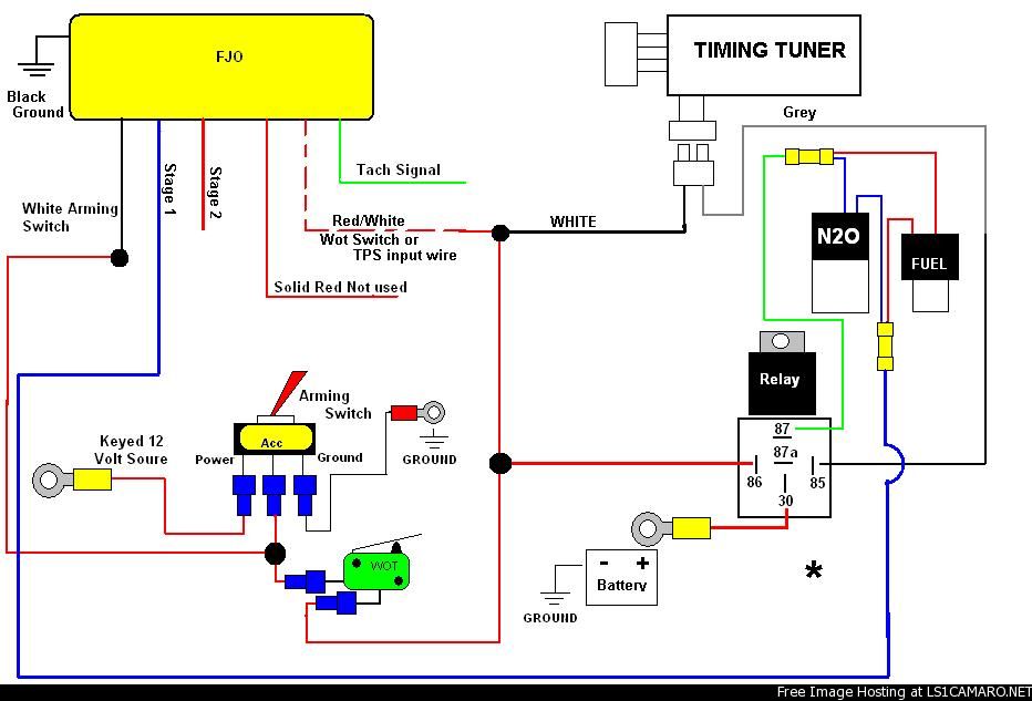
WHITE -- Switched 12V (fused 5 amp)
WHITE/RED -- Throttle Postion Sensor (TPS)
RED -- Trigger Switch Input (12V) (Explanation of the Trigger Switch)
GREEN -- RPM
BLACK -- Controller Ground
================
Wire Descriptions (Driver aka larger wires)
BLUE -- To Stage 1 Solonoid Ground
RED -- To Stage 2 Solonoid Ground
BLACK(12AWG) -- Ground from solonoid driver that can handle 80 Amps
*Note: Do NOT ground Driver to ECU ground to prevent inteference
PCM Connections (If Using FJO as WOT/Window) - Link to Post
TPS:
LS1 Dark Blue Wire Red Connector on PCM, pin 24, Dark Blue Wire
LS1 – 98 ONLY - Dark Blue Wire Pin 12 on PCM, Dark Blue Wire
RPM:
LS1 White Wire Red Connector on PCM, pin 10, White Wire
LS1 – 98 ONLY - White Wire Blue Connector on PCM, Pin 35 on PCM, White Wire
Basic Relay Info - (Based on Bosch 5-Pin) (How-Stuff-Works (Relays)
85 - Ground
30 - 12V+ (should be fused)
86 - Keyed 12V (Enables Relay / Generally Lower Amp / Arming Switch etc.)
87 - 12V to Device (On when 86 is hot)
87a - 12V to Device (On when 86 is NOT hot)
Wire Gauge Tables - LINK
12-14AWG Wire Generally Used for 12V higher-amp applications (noids,heater,etc.)
*When in doubt look at the char above depending on amps and length of the wire.
Wiring Diagrams
FJO(Single) + Timing Tuner + Manual WOT

Last edited by Johnny5; 05-29-2006 at 03:51 PM.
#3
Originally Posted by red fury
TPS for LS1 = rise
LS1 RPM multiplier = divide by 2
LS1 RPM multiplier = divide by 2
The RPM multiplier would depend on if your hooking to the tach wire or to an injector or coil wire to get RPM's.
#4
Originally Posted by rocket5979
The RPM multiplier would depend on if your hooking to the tach wire or to an injector or coil wire to get RPM's.
so which is it for the stock tach wire? divide by 2?


