


Porting Heads - And so it begins.......
Thread Starter
11 Second Club
iTrader: (37)
Joined: Mar 2004
Posts: 2,046
Likes: 3
From: Vancouver, WA
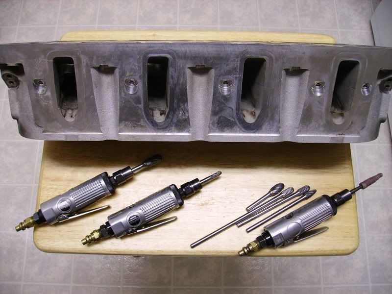
After much deliberating, I decided to port my own LSx heads. I got some used 5.3l heads from Tom Wong (thanks Tom) for a good price, and they were local. Got another great deal on some brand new Manley 2.00/1.60 LSx stainless valves, so off I go. Some of you know that I've ported a half dozen LT1 heads with good success (read here under DIY Head Porting: http://members.***.net/gmarengo/)
Had these stock 5.3's flowed with the stock, super-tiny 1.89/1.55 valves. The guy that flowed them wants to learn more about the LSx stuff, so he has offered to flow test them for me for FREE if I share my porting techniques with him. It's a great deal for me considering he normally charges $60/chamber, per flow test. In reality, I'm shooting for numbers in the mid 290 range for the intake, and around 220ish, both at .500-.550 lift range. I got mid 270's out some LT1 heads, so this should be a cake walk with these "glory" heads,,,, at least I hope.
Anyway, I'm going to be taking many photos, and documenting the port work along the way. Thought maybe you guys would like to see the progress as it happens so I'll update as progress permits.
Here are the stock flow #'s @ 28":
lift........./ int../ exh
.200...... 136.... 105
.250...... 167.... 121
.300...... 192.... 137
.350...... 211.... 155
.400...... 223.... 171<-- became turbulent on intake side
.450...... 223.... 190
.500...... 224.... 203
.550...... 228.... 213
.600...... 233.... 217
.650...... 237.... 218
.700...... 239.... 221
EDIT, Here are the "after porting" flow numbers.
lift........./ int../ exh
.200...... 131.... 111
.250...... 160.... 131
.300...... 190.... 149
.350...... 217.... 168
.400...... 240.... 183
.450...... 257.... 201
.500...... 273.... 217
.550...... 283.... 228
.600...... 289.... 235
.650...... 295.... 241
.700...... 298.... xxx
Here's some pics of the stockers as-is:
And no,,,, I'm not porting these in my kitchen.
Mike
Last edited by Mikey 97Z M6; Dec 15, 2006 at 08:05 PM.
Good luck. It's a lot of bloody work for sure. I used to do my own SBC heads years back. I even had my own valve seat grinder. I can still taste the shavings/dust to this day. Maybe I should have worn a mask, but back then men were men and sheep were still valuable.
Robert
Robert
I would recommend experimenting with different valves as well. You will be suprised at the difference in results. Whatever valve you go with make sure they are backcut as this will help with flow.
Thread Starter
11 Second Club
iTrader: (37)
Joined: Mar 2004
Posts: 2,046
Likes: 3
From: Vancouver, WA
Originally Posted by Robert56@NitrousDirect
Good luck. It's a lot of bloody work for sure. I used to do my own SBC heads years back. I even had my own valve seat grinder. I can still taste the shavings/dust to this day. Maybe I should have worn a mask, but back then men were men and sheep were still valuable.
Robert
Robert

These pictures suck because my camera doesn't like to take close up shots. It can't focus that close. I have another cheapo camera that zooms closer and takes better pictures close up. I'll use that one for all my other photos. I'm hoping to get started on these this weekend.

DrkPhx, Ya, I believe the Manleys come stock with a backcut on them already. I remember when I was doing the LT1's, the guy doing the seat cuts suggested a back cut on the exhaust valves and it picked up 8cfm between .450 and .550 lifts. Quite amazing what a small change can make in flow.
Mike
Focus on the straight side especially around the ramp area and up into short side. That side shows a lot of gains the 2" before the short turn. Pull the ramp down, but don't try to remove as it will get thin. You'll see huge gains there. Also the front rocker bump can be removed, I'm sure you know that. I would do chamber work on the 5.3's as well. Unshroud the valves and roll over the sparkplug boss.
Thread Starter
11 Second Club
iTrader: (37)
Joined: Mar 2004
Posts: 2,046
Likes: 3
From: Vancouver, WA
Originally Posted by Jantzer98SS
Focus on the straight side especially around the ramp area and up into short side. That side shows a lot of gains the 2" before the short turn. Pull the ramp down, but don't try to remove as it will get thin. You'll see huge gains there. Also the front rocker bump can be removed, I'm sure you know that. I would do chamber work on the 5.3's as well. Unshroud the valves and roll over the sparkplug boss.
Again, thanks for the tips.
Mike
Trending Topics
Thread Starter
11 Second Club
iTrader: (37)
Joined: Mar 2004
Posts: 2,046
Likes: 3
From: Vancouver, WA
Made some progress on the heads today. It took a bit to figure out exactly where I wanted to remove material from etc., but the other ports should come together pretty fast. I concentrated on the intake port today, as the exhaust isn't going to need much work anyway.
Nate, I cleared my PM box also...
Here's some pics from today's porting:
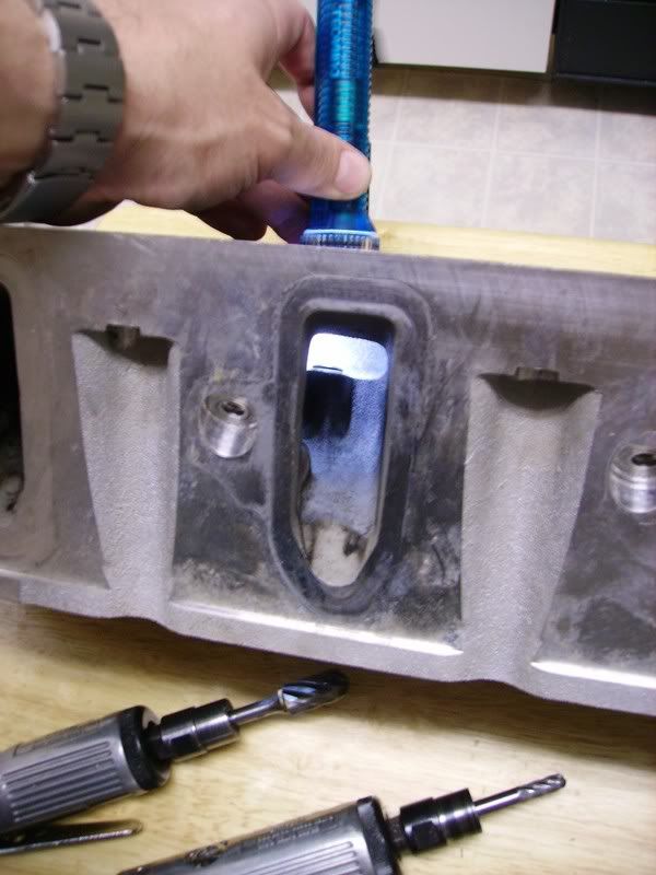
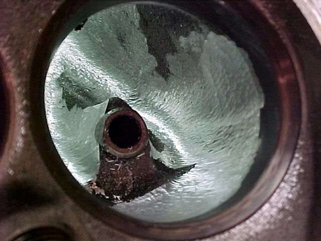
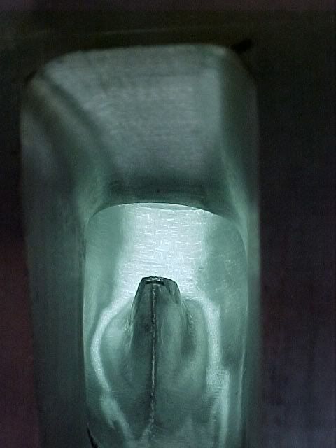
Roughing in the intake entry. Sorry these turned out a bit dark.
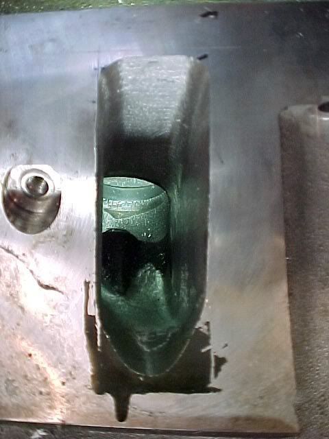
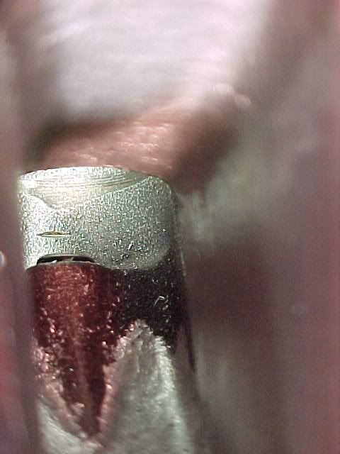
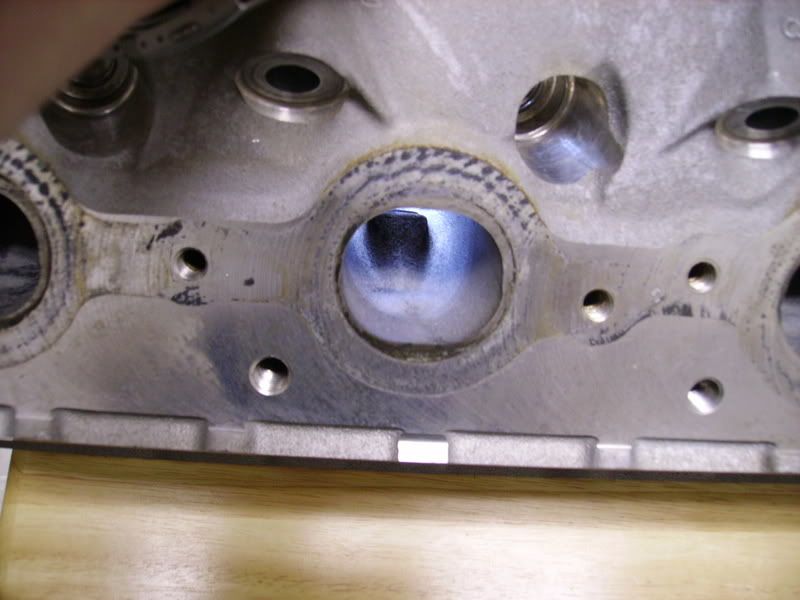
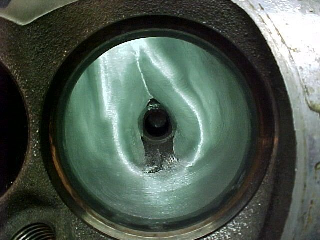
Here I just did some rough shaping in the bowl area, blending the intake porting into the bowl and shaping the valve guide area.
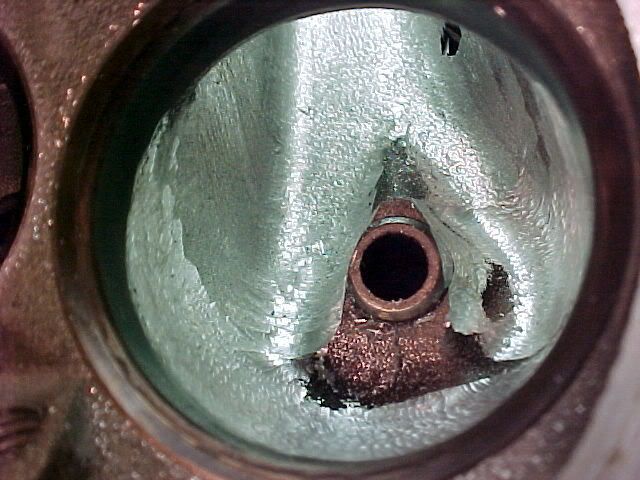
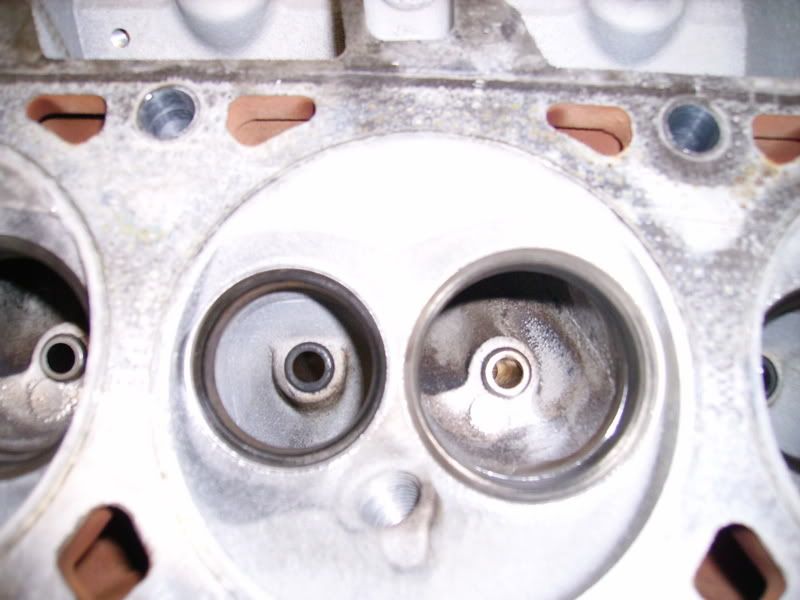
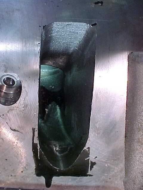
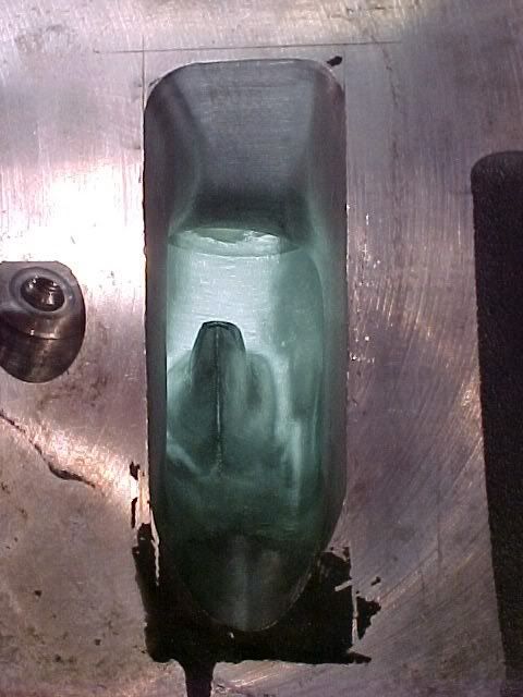
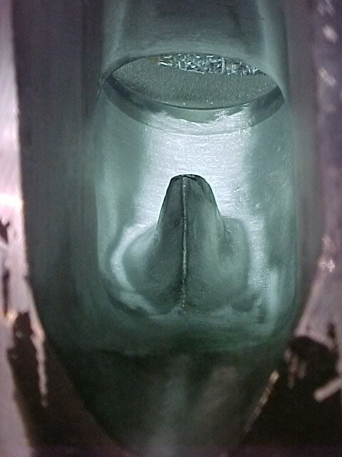
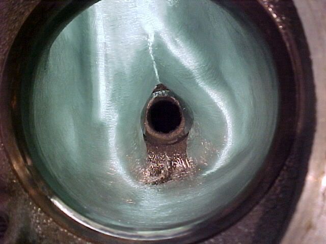
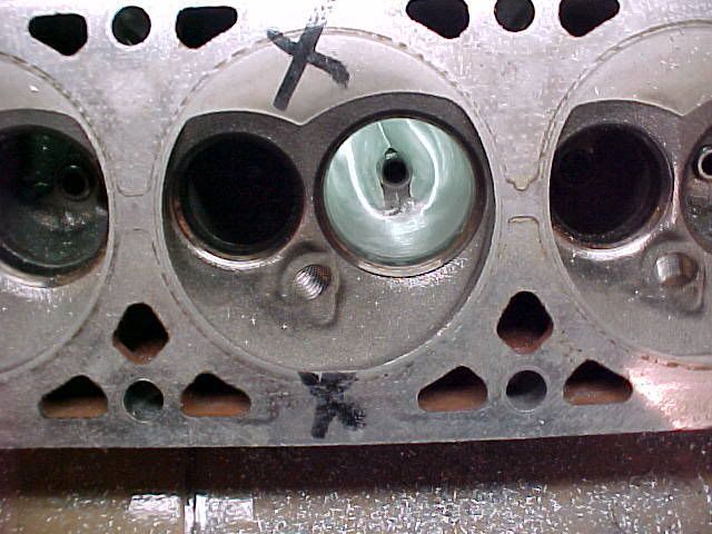
Here's some pics after I completed all the shaping, then hit the entire port/bowl with a cartridge roll. I'm fairly pleased with how this one turned out. These LSx heads are a walk in the park compared to porting an LT1 head. I have about 2.25 hours into this port and it was my first one. The rest will go quickly if this flows worth a ****.
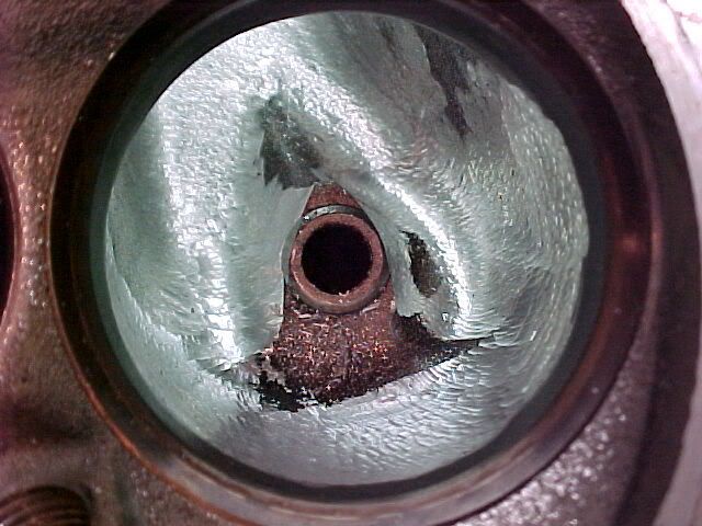
Tomorrow I'll be doing the exhaust runner and unshrouding some valves in chamber area. Fun stuff..........
Nate, I cleared my PM box also...
Here's some pics from today's porting:
Roughing in the intake entry. Sorry these turned out a bit dark.
Here I just did some rough shaping in the bowl area, blending the intake porting into the bowl and shaping the valve guide area.
Here's some pics after I completed all the shaping, then hit the entire port/bowl with a cartridge roll. I'm fairly pleased with how this one turned out. These LSx heads are a walk in the park compared to porting an LT1 head. I have about 2.25 hours into this port and it was my first one. The rest will go quickly if this flows worth a ****.
Tomorrow I'll be doing the exhaust runner and unshrouding some valves in chamber area. Fun stuff..........
LS1 Tech Stories
The Best V8 Stories One Small Block at Time

Gas Monkey Built a 6-Wheel Ferrari Testarossa With a Corvette LT4 Engine
Verdad Gallardo
7 Most Reliable High-Performance Engines GM Has Ever Built
Verdad Gallardo
Amazing '71 Camaro Restomod Is Modern Muscle Car Under the Skin
Verdad Gallardo
6 Common C5 Corvette Failures and What's Involved In Repairing Them
Pouria Savadkouei
Retro Modern Bandit Pontiac Trans AM Comes With Burt Reynolds' Autograph
Verdad Gallardo
Top 10 Greatest Cadillac V Series Performance Models Ever, Ranked
Pouria Savadkouei
Top 10 Most Powerful Chevy Trucks Ever Made!

Hennessey's New Supercharged Silverado ZR2 Has 700 HP
Verdad Gallardo
Coachbuilt N2A Anteros Is an LS2-Powered C6 Corvette In Italian Clothes
Verdad Gallardo Thread Starter
11 Second Club
iTrader: (37)
Joined: Mar 2004
Posts: 2,046
Likes: 3
From: Vancouver, WA
Thanks guys.
Eric, ya, I'll be finishing up this chamber and then it's back to the flow test again. I'm gonna drop off the head on Mon. and I hope to get it back by the following weekend. I'll probably finish up all the exhaust runners on this head tomorrow, and might start with some simple stuff on the other head during the week. Most of the things I would change (if any) are going to be in the bowl area and short side radius so there is quite a bit of work I can do on the other head while this one is getting tested.
I'll be happy if they achieve 290+ cfm at .500-.550 lift. We'll see........
Mike
TECH Addict
Joined: May 2004
Posts: 2,564
Likes: 0
From: Bellingham/Edmonds, WA
I'm pretty excited to see these numbers. If you really can gain 25% more flow at peak lift for the work you did that would be pretty cool! Maybe I should start toying with my parts head. I read your writeup and the links on your page, seems pretty straight forward. Even if I could get the head from 230 to 260 or so @ .450" that would be sweet.
What are those bits on your die grinders? They look like they would take away material crazy fast..
What are those bits on your die grinders? They look like they would take away material crazy fast..
Thread Starter
11 Second Club
iTrader: (37)
Joined: Mar 2004
Posts: 2,046
Likes: 3
From: Vancouver, WA
Originally Posted by Jantzer98SS
You did a damn good job. I would not have done it any different. If the short side doesn't get turbulent, I would guess 300+ flow at .600. I will elaborate tomorrow, congrats!
Originally Posted by Poik
I'm pretty excited to see these numbers. If you really can gain 25% more flow at peak lift for the work you did that would be pretty cool! Maybe I should start toying with my parts head. I read your writeup and the links on your page, seems pretty straight forward. Even if I could get the head from 230 to 260 or so @ .450" that would be sweet.
What are those bits on your die grinders? They look like they would take away material crazy fast..
What are those bits on your die grinders? They look like they would take away material crazy fast..
Those bits, or "burs", are specific for porting. The super aggressive ones are for non-ferrous material, the others are for ferrous metals (alum/iron respectively). I use the alum burs for shaping, and the iron burs for smoothing, blending, then the cartridge rolls (sand paper) for final smoothing. If you're interested in porting, contact a local machine shop and find out who supplies them with their burs/bits. Summit racing has limited sources for them also, or find an online supplier. They're not cheap though, and average between $15-25 each depending on diameter and length.
Mike
Last edited by Mikey 97Z M6; Dec 10, 2006 at 02:45 AM.
TECH Addict
Joined: May 2004
Posts: 2,564
Likes: 0
From: Bellingham/Edmonds, WA
Yeah the images don't show up for me on the page, but when you click on them most come right up. I also read the Standard Abrasives general porting guide and it had a lot of good info. I'll ask my local guy about the burs when I drop the head off for cleaning, thanks

Thread Starter
11 Second Club
iTrader: (37)
Joined: Mar 2004
Posts: 2,046
Likes: 3
From: Vancouver, WA
Originally Posted by Nate98z28
Lookin good Mikey. Are you going to do any chamber work? The spark plug bosses in those heads need some serious work. Also I would suggest throwing a d-shape on the exhaust runner.
Nate
Nate
I have pictures of the new work from yesterday, but I forgot my damn camera at home. If I have time, I'll swing by there after dropping off the head so I can get some more pics up this afternoon.....
Ackattack, I'll mention it to Dennis, but I allready know what he's going to say about it. He's flowing them for free, so I pretty much gotta go with whatever he decides to do.
Mike
You need to get rid of that knife edge on the back of the intake guide. Sharp edges do nothing but making air turbulent. I wish you the best, but without knowing what you are doing with the valve job and valve back cut, they are not going to flow over 290.

Originally Posted by Mikey 97Z M6
Ackattack, I'll mention it to Dennis, but I allready know what he's going to say about it. He's flowing them for free, so I pretty much gotta go with whatever he decides to do.
Mike
Mike