
Would unplugged knock sensors reduce power?
 12-21-2010, 01:20 PM
#1
On The Tree
Thread Starter
iTrader: (1)

Join Date: Jun 2009
Location: Rockland County, NY
Posts: 141
Likes: 0
Received 0 Likes
on
0 Posts
I got a 98 T/A and just got a tune from RPM in DE. Here is the set up
-FAST 92/92
-TSP True Duals
-TSP 233/239 Cam
-799 Heads (2006 vette)
-46lb injectors
While tuning I didn't have the knock sensors plugged into the harness. Would this reduce power??? If so how much?
-FAST 92/92
-TSP True Duals
-TSP 233/239 Cam
-799 Heads (2006 vette)
-46lb injectors
While tuning I didn't have the knock sensors plugged into the harness. Would this reduce power??? If so how much?
 12-21-2010, 04:05 PM
#2
Moderator
iTrader: (11)
Join Date: Mar 2002
Location: East Central Florida
Posts: 12,604
Likes: 0
Received 6 Likes
on
6 Posts

If they were unplugged, the car should have faulted to
open loop and been tuned to pretty near dead-on under
those conditions. It would then cost you no power.
Now, if you plug them in and trimming pulls the tune rich
(as often happens with headers in closed loop), -that-
would cost you economy and WOT performance.
Personally I think you might like open loop better. At
least when the weather's anything close to when you
were tuned.
12-21-2010, 05:09 PM
#3

If they were unplugged, the car should have faulted to
open loop and been tuned to pretty near dead-on under
those conditions. It would then cost you no power.
Now, if you plug them in and trimming pulls the tune rich
(as often happens with headers in closed loop), -that-
would cost you economy and WOT performance.
Personally I think you might like open loop better. At
least when the weather's anything close to when you
were tuned.
open loop and been tuned to pretty near dead-on under
those conditions. It would then cost you no power.
Now, if you plug them in and trimming pulls the tune rich
(as often happens with headers in closed loop), -that-
would cost you economy and WOT performance.
Personally I think you might like open loop better. At
least when the weather's anything close to when you
were tuned.
12-21-2010, 11:48 PM
#5
On The Tree
Thread Starter
iTrader: (1)
Join Date: Jun 2009
Location: Rockland County, NY
Posts: 141
Likes: 0
Received 0 Likes
on
0 Posts
CalEditor, can you tell me why exactly this would cause a reduction of power? A couple of tuners I spoke to said it wouldn't have any effect. If they arent plugged in, they are not going to detect knock, and wont pull timing. I just wana know why I'm down on power.
 12-22-2010, 06:23 AM
#7
N0DIH One tip to remember.
1 degree past Mean Best Torque makes less power than 10 degrees before Mean Best Torque.
Too much meaning past Mean Best Torque. Point of Pinging isn't MBT. So don't get carried away, just because it doesn't ping doesn't mean that that you can keep increasing timing and make more power.
1 degree past Mean Best Torque makes less power than 10 degrees before Mean Best Torque.
Too much meaning past Mean Best Torque. Point of Pinging isn't MBT. So don't get carried away, just because it doesn't ping doesn't mean that that you can keep increasing timing and make more power.
Last edited by CalEditor; 12-22-2010 at 09:00 AM.
Trending Topics
 12-22-2010, 01:25 PM
#10
On The Tree
Thread Starter
iTrader: (1)
Join Date: Jun 2009
Location: Rockland County, NY
Posts: 141
Likes: 0
Received 0 Likes
on
0 Posts
400/390 on their Dynojet. Torque sounds right but hp and torque numbers seem too close to each other. Manager thinks it should be in the 420-430 range
12-22-2010, 03:49 PM
#13
Moderator
iTrader: (11)
Join Date: Mar 2002
Location: East Central Florida
Posts: 12,604
Likes: 0
Received 6 Likes
on
6 Posts
I do not know whether sensors being unplugged drives
knock learn factor. That is a spark-learning deal. What
do you see for delivered timing, and does it match what
is in the HO timing table (if you have that info) or what
your tuner said he did? Do you have logging ability?
When you say "down on power" is that a recorded or
butt-dyno from day-of-tune to present, or is this all just
numbers vs expectations? Dynos are notoriously variable
with all kinds of corrections and fudging.


 12-25-2010, 10:28 AM
#18
12-25-2010, 06:54 PM
#19
Knock Sensor System Description
Purpose
The knock sensor (KS) system enables the powertrain control module (PCM) to control the ignition timing advance for the best possible performance while protecting the engine from potentially damaging levels of detonation. The sensors in the KS system are used by the PCM as microphones to listen for abnormal engine noise that may indicate pre-ignition/detonation.
Sensor Description
There are 2 types of KS currently being used:
Both sensors use piezo-electric crystal technology to produce and send signals to the PCM. The amplitude and frequency of this signal will vary constantly depending on the vibration level within the engine. Flat response and broadband KS signals are processed differently by the PCM. The major differences are outlined below:
One way the control module monitors the system is by output of a bias voltage on the KS signal wire. The bias voltage creates a voltage drop that the control module monitors and uses to help diagnose KS faults. The KS noise signal rides along this bias voltage, and due to the constantly fluctuating frequency and amplitude of the signal, will always be outside of the bias voltage parameters.
Another way the control module monitors the system is by learning the average normal noise output from the KS. The control module learns a minimum noise level, or background noise, at idle from the KS and uses calibrated values for the rest of the RPM range. The control module uses the minimum noise level to calculate a noise channel. The control module uses this noise channel, and the KS signal that rides along the noise channel, in much the same way as the bias voltage type does. As engine speed and load change, the noise channel upper and lower parameters will change to accommodate the normal KS signal.
KS diagnostics can be calibrated to detect faults with the KS diagnostic inside the PCM, the KS wiring, the sensor output, or constant knocking from an outside influence such as a loose or damaged component. In order to determine which cylinders are knocking, the PCM uses KS signal information when the cylinders are near top dead center (TDC) of the firing stroke.
NOTE:
The minimum noise level must be learned. The minimum noise level is learned when the following conditions are met:
The PCM uses a knock sensor (KS) to detect abnormal vibration in the engine (detonation/spark knocking). Mounted in the engine block, under the intake manifold, the knock sensor produces an AC signal at all engine speeds and loads. The PCM then adjusts the spark timing based on the amplitude and frequency of the KS signal.
A knock sensor module is no longer used to diagnose the knock sensor system. The circuitry is integrated into the PCM. The PCM uses the knock sensor signal to calculate an average voltage. Then, the PCM assigns a voltage range above and below the average voltage value. The PCM checks the knock sensor and related wiring by comparing the actual knock signal to the assigned voltage range. A normal knock sensor signal should vary outside the assigned voltage range (as shown in the normal knock sensor figure). If PCM detects a signal voltage within the assigned voltage range, DTC P0327 will set (as shown in the abnormal knock sensor figure).
Good KS
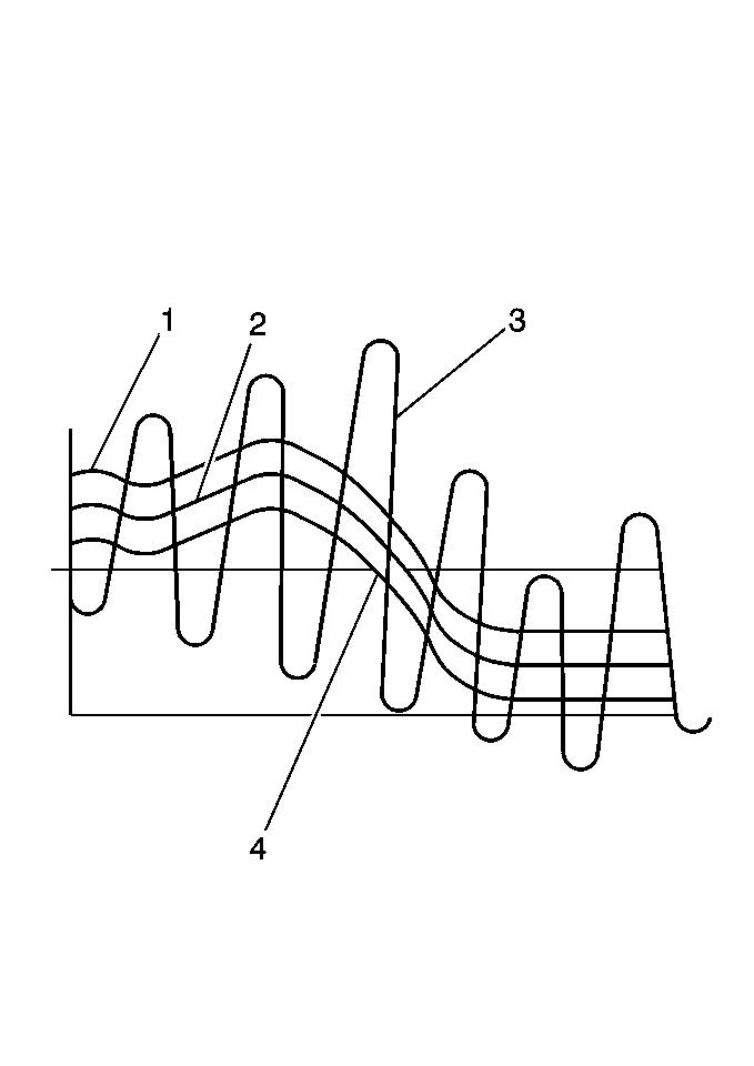
(1) Upper Fail Region
(2) Knock Sensor Calculated Average
(3) Knock Sensor Signal (Normal)
(4) Lower Fail Region
Bad KS
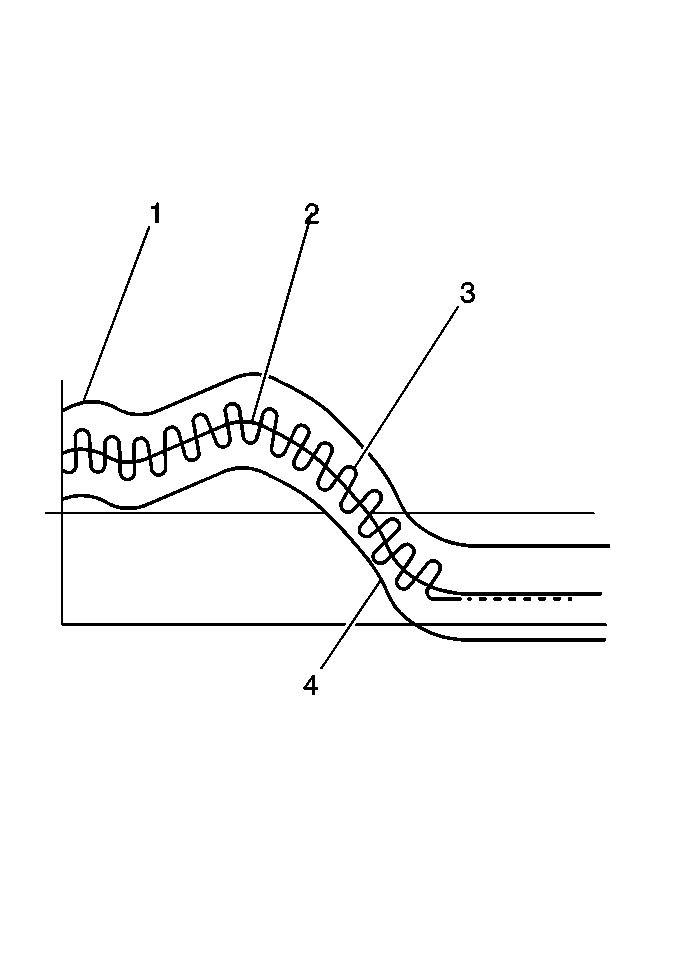
(1) Upper Fail Region
(2) Knock Sensor Calculated Average
(3) Knock Sensor Signal (Failed)
(4) Lower Fail Region
Purpose
The knock sensor (KS) system enables the powertrain control module (PCM) to control the ignition timing advance for the best possible performance while protecting the engine from potentially damaging levels of detonation. The sensors in the KS system are used by the PCM as microphones to listen for abnormal engine noise that may indicate pre-ignition/detonation.
Sensor Description
There are 2 types of KS currently being used:
- The broadband single wire sensor
- The flat response 2-wire sensor
Both sensors use piezo-electric crystal technology to produce and send signals to the PCM. The amplitude and frequency of this signal will vary constantly depending on the vibration level within the engine. Flat response and broadband KS signals are processed differently by the PCM. The major differences are outlined below:
- All broadband sensors use a single wire circuit. Some types of controllers will output a bias voltage on the KS signal wire. The bias voltage creates a voltage drop the PCM monitors and uses to help diagnose KS faults. The KS noise signal rides along this bias voltage, and due to the constantly fluctuating frequency and amplitude of the signal, will always be outside the bias voltage parameters. Another way to use the KS signals is for the PCM to learn the average normal noise output from the KS. The PCM uses this noise channel, and KS signal that rides along the noise channel, in much the same way as the bias voltage type does. Both systems will constantly monitor the KS system for a signal that is not present or falls within the noise channel.
- The flat response KS uses a 2-wire circuit. The KS signal rides within a noise channel which is learned and output by the PCM. This noise channel is based upon the normal noise input from the KS and is known as background noise. As engine speed and load change, the noise channel upper and lower parameters will change to accommodate the KS signal, keeping the signal within the channel. If there is knock, the signal will range outside the noise channel and the PCM will reduce spark advance until the knock is reduced. These sensors are monitored in much the same way as the broadband sensors, except that an abnormal signal will stay outside of the noise channel or will not be present.
One way the control module monitors the system is by output of a bias voltage on the KS signal wire. The bias voltage creates a voltage drop that the control module monitors and uses to help diagnose KS faults. The KS noise signal rides along this bias voltage, and due to the constantly fluctuating frequency and amplitude of the signal, will always be outside of the bias voltage parameters.
Another way the control module monitors the system is by learning the average normal noise output from the KS. The control module learns a minimum noise level, or background noise, at idle from the KS and uses calibrated values for the rest of the RPM range. The control module uses the minimum noise level to calculate a noise channel. The control module uses this noise channel, and the KS signal that rides along the noise channel, in much the same way as the bias voltage type does. As engine speed and load change, the noise channel upper and lower parameters will change to accommodate the normal KS signal.
KS diagnostics can be calibrated to detect faults with the KS diagnostic inside the PCM, the KS wiring, the sensor output, or constant knocking from an outside influence such as a loose or damaged component. In order to determine which cylinders are knocking, the PCM uses KS signal information when the cylinders are near top dead center (TDC) of the firing stroke.
NOTE:
The minimum noise level must be learned. The minimum noise level is learned when the following conditions are met:
- The engine coolant temperature (ECT) is more than 60�C (140�F).
- The engine RPM is between 475-975 for 10 seconds.
The PCM uses a knock sensor (KS) to detect abnormal vibration in the engine (detonation/spark knocking). Mounted in the engine block, under the intake manifold, the knock sensor produces an AC signal at all engine speeds and loads. The PCM then adjusts the spark timing based on the amplitude and frequency of the KS signal.
A knock sensor module is no longer used to diagnose the knock sensor system. The circuitry is integrated into the PCM. The PCM uses the knock sensor signal to calculate an average voltage. Then, the PCM assigns a voltage range above and below the average voltage value. The PCM checks the knock sensor and related wiring by comparing the actual knock signal to the assigned voltage range. A normal knock sensor signal should vary outside the assigned voltage range (as shown in the normal knock sensor figure). If PCM detects a signal voltage within the assigned voltage range, DTC P0327 will set (as shown in the abnormal knock sensor figure).
Good KS
(1) Upper Fail Region
(2) Knock Sensor Calculated Average
(3) Knock Sensor Signal (Normal)
(4) Lower Fail Region
Bad KS
(1) Upper Fail Region
(2) Knock Sensor Calculated Average
(3) Knock Sensor Signal (Failed)
(4) Lower Fail Region