Polarity of Gen IV knock sensors
#4
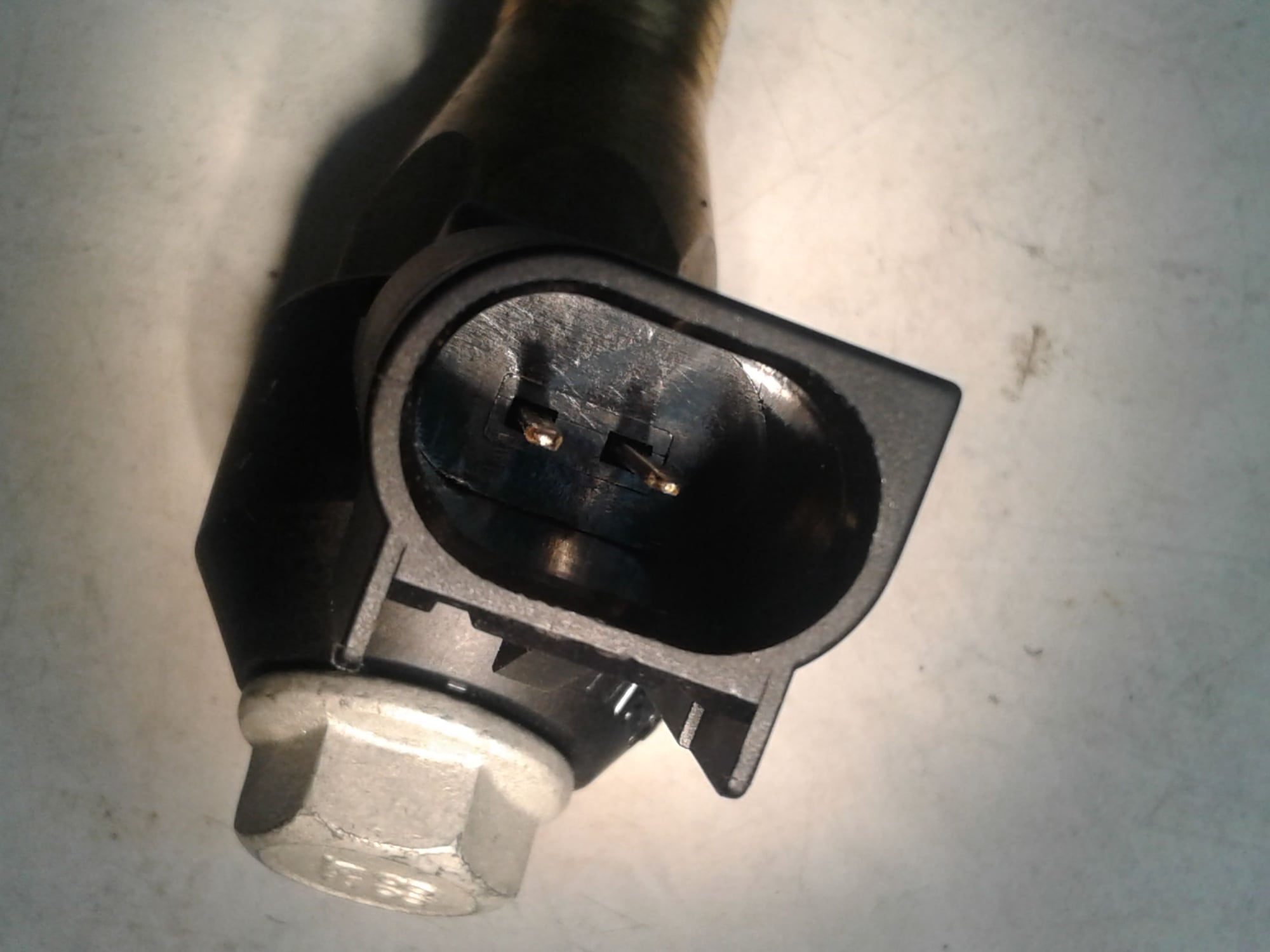
There is no continuity between the pins or to the case. But I found the answer here, https://www.lsenginediy.com/sensors-inputs-guide/ , and then found pictures of which pin has which color wire.
This is also an interesting article for people that want to know more about how it works. http://www.wellsve.com/sft503/counterp_v12_i2_2008.pdf
This is also an interesting article for people that want to know more about how it works. http://www.wellsve.com/sft503/counterp_v12_i2_2008.pdf
#6
TECH Enthusiast
You don't really know what's in the black box. It may well be a circuit that expects the polarity of applied voltage across it to be in a particular direction, even if it's not directly tied to chassis ground at that pin. There may be other stuff between that pin and ground that's inside the PCM. The sensor is only part of the circuit.
Trending Topics
#8
10 Second Club
iTrader: (26)
You don't really know what's in the black box. It may well be a circuit that expects the polarity of applied voltage across it to be in a particular direction, even if it's not directly tied to chassis ground at that pin. There may be other stuff between that pin and ground that's inside the PCM. The sensor is only part of the circuit.
#9
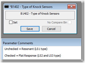
* Looks like the strategy portion is available to you in the software. (Check that box off.
 )
)* You would need to add a ground wire back to ECM to complete the hardware portion. I don't know if the ECM has a ground pin assigned for that function or not.
I did the switch using Holley HP EFI. In that case both Gen III and Gen IV knock sensors use the same +5V reference wire, but I had to plumb in a Ground reference wire for the Gen IV knock sensor and select the correct strategy in the software.
#11
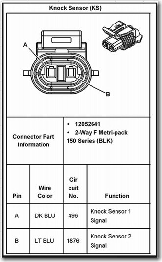
Judging by the wire colors, I think those are the two 5V wires that go to the two 1-wire knock sensor that are typically mounted in the valley of the engine block.
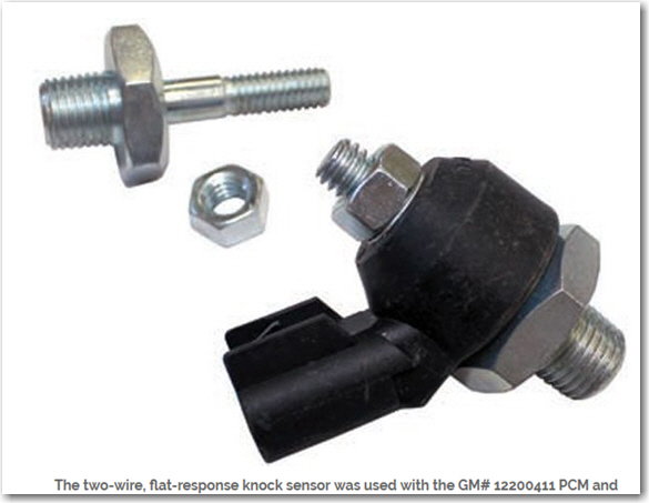
If you want to change over to the 2-wire knock sensor mounted in the sides of the block then you reuse those wires and add extra wires for the ground back to ECM.
With my Holley HP EFI I tied the ground into the same common ground that all the sensors use. I don't know what you need to do for your particular ECM. You'll need to figure that out.
#13
That's not the connector that plugs into the knock sensor. It's just a plug where you're expected to finish the harness to knock sensors.
The answer is right there in the picture you posted. Those are the two signal wires that go to the two 1-wire knock sensors, one for left hand and one for right hand. You need to buy or make your own sub-harness to the knock sensors
The answer is right there in the picture you posted. Those are the two signal wires that go to the two 1-wire knock sensors, one for left hand and one for right hand. You need to buy or make your own sub-harness to the knock sensors
#14
Launching!
iTrader: (4)
Join Date: Oct 2004
Location: DFW
Posts: 217
Likes: 0
Received 0 Likes
on
0 Posts


Ok, I see now what you are saying - guess I'm having a senior moment. I even tried connecting the harness plug to the sensor and it doesn't work. I found these two pigtails:
https://www.eficonnection.com/home/product/knock-detonation-sensor-2-wire-flat-response-ls2-ls3-ls7-connector-pigtail for GM LS2 LS3 LS7 Gen IV 58x LS-Series Knock Sensors but discussion says 24x also
https://www.eficonnection.com/home/p...nector-pigtail for GM 2001-2005 4.3L Vortec engines
Looks like I have the LS2-3-7 ks - but both have a blue wire and a gray wire - so I'm guessing the gray is the ground you spoke of. Your suggestion to connect to the sensor common ground is probably correct - I hadn't noticed a common ground on the pinout table - I'll have to review again. Thanks for pointing out the errors of my thought process.


