When you click on links to various merchants on this site and make a purchase, this can result in this site earning a commission. Affiliate programs and affiliations include, but are not limited to, the eBay Partner Network.
Complete Racetronix Fuel system install and product review
I've not read of many people doing the complete Racetronix fuel line and rail kit install, I understand it is a relatively new product. I couldn't find much information on it when I was considering it, so I though I would share my findings with others.
Parts I purchased to do the install on my '98 include :
DPA-680 dual 340 lph pump assembly - $248
FLK-F98 deluxe fuel line kit with rails - $543
FPWH-002 fuel pump hot wire - $49 - I know this is not correct for dual pumps but since I already had one on my car, I know I can build a dual one from the 2 single ones.
Miscelaneous hardware, about $20
So a total fuel system to support about 1200 whp can be built for about $850 using this kit. Compared to competitive products out there, the fuel lines and rails are going for about $1000 and dual pump setups for about $600. This is about half that price, and the components look and feel like quality parts.
Lets start with discussing the components.
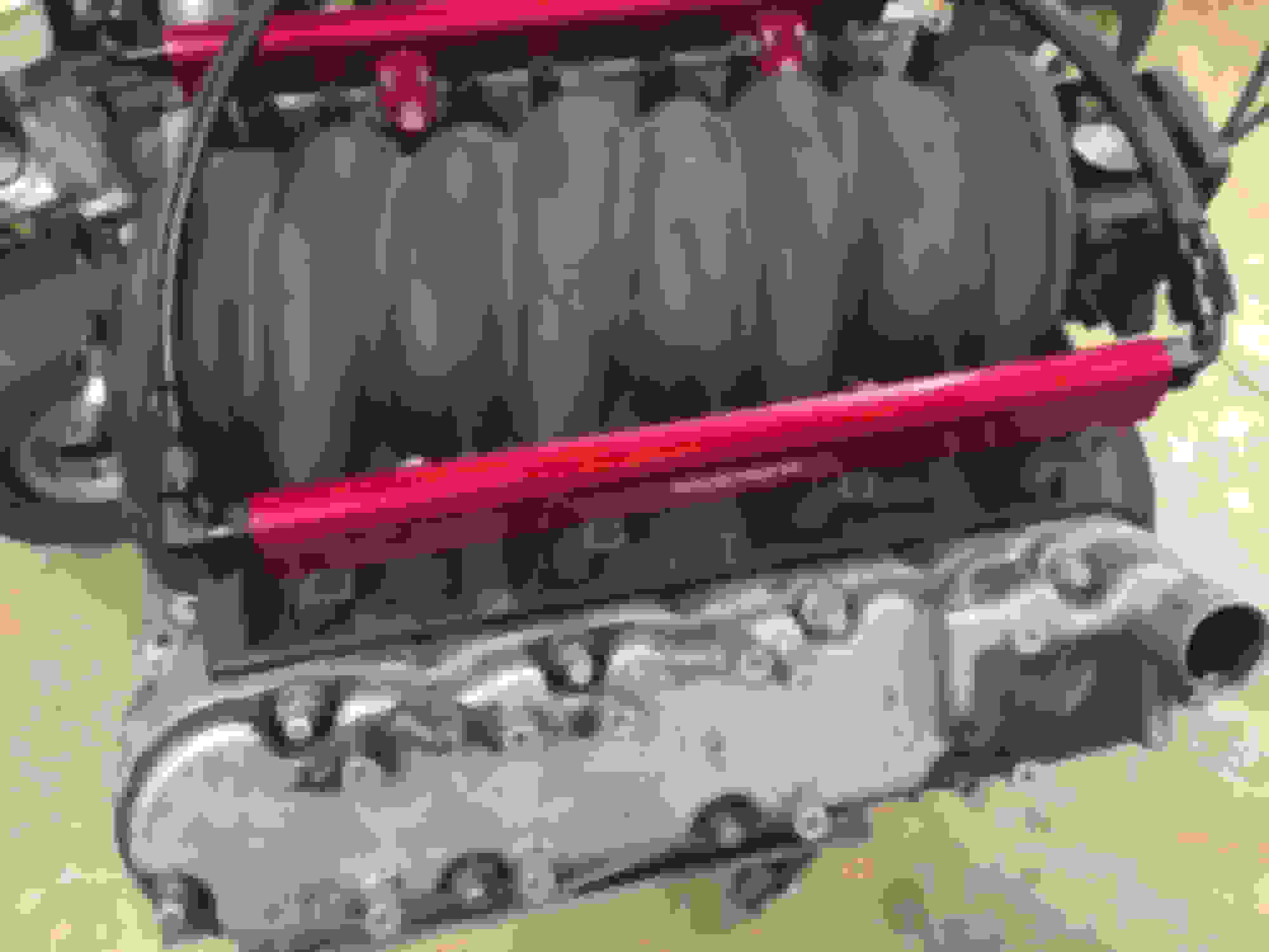
The fuel rails look nice, and are 3/4" inside. This is larger than almost all other kits which are 5/8". The downside of this is it may cause a clearance issue with our factory intake manifolds. They hit on the bosses that the manifold bolst go down through, to hold the intake manifold to the heads. This contact may cause a vacuum leak around the o-rings on the bottom of the injectors, and it may not. It is a very slight contact, I'd estimate only about 10 to 20 thousands of an inch out of being straight in. The o-ring may be able to make up for this. I'll follow up later and let you know if I need to clearance it. I mocked it up on a spare engine before trying to put it in the car.
The hoses seem top notch, conductive PTFE braided stainless with a black Hytrel covering. Hose is rated at 450F continuous heat exposure and 500F intermittent. For a turbo car this is great. I don't intend to mount my hoses anywhere it will get close to that temperature, but I like the insurance.
Fittings are all really nice, the typical black anodized aluminum type with the olive for use with PTFE hose. You can see the hose and fittings in the previous photo. I like the stealth look the black hose and black fittings bring, it sets off the red rails.
Next is the fuel pressure regulator which is boost referenced. It seems like a really nice piece. Also a filter and bracket is included. You will see photos of these in the installation.
The dual pumps have a really nice aluminum coupler and stainless steel bracket to hold them in place as well and new wiring harnesses and sock filters are included.
Overall I feel I got huge value for $850, super nice components, but a tremendous amount of work and planning required. This is not just a drop in, bolt on, and go system. You will need to plan, fabricate some brackets, and do all your own hose end installations, as well as some wiring. I don't want to say you need to be a rocket scientist, because you don't, but it will take a little time and craftsmanship to get it right. I would estimate 15-20 hours total time investment. It typically takes me about 30 minutes just to do a hose end installation, cutting the hoses, trimming back the Hytrel, and the stainless braid just the right amount to get the olive and fitting to go on smoothly and not leak. There are at least 10 hose end installs required.
Lets start with the fuel sending unit and what is required there.
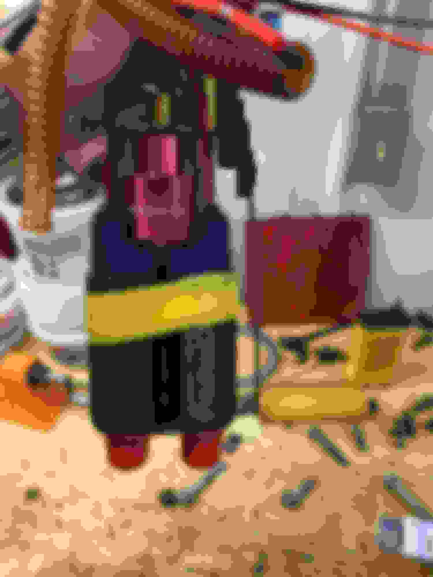
This is how my unit looked after I pulled it out and tore it down. I had a drop in Racetronix 255 lph kit in the car for the last 5 years. I removed the factory regulator off the return since I'll be using an external regulator at the rails.
I took a die grinder and opened up the top plastic area which anchored the single pump. I made the opening large enough for the dual pump assembly to slide in, but not too large where it was loose. It was a snug fit.
I cut off the bottom of the factory bracket, a taped the pumps in place so the bottom of the new pumps was flush to the same depth the original single pump came down to. This maintained the same over all length of the assembly.
I also taped it in position so I was sure it would not interfere with the float mechanism.
I then did something I've not seen done before, I tack welded the pump bracket in place to ensure the over all length was maintained, and the pumps would not shift to interfere with the float mechanism, exactly where I had taped it to be.
After I tacked it I removed the tape, and put on the typical 3-4" hose clamp around the pumps in the middle. It is now Damn! solidly mounted. It is held by the plastic at the top, the clamp in the middle and the weld at the base. It's not moving. I installed the filter socks, and put a piece of 3/8" fuel injection hose from the pump outlet barb to the top of the assembly. The pump barb from the dual pumps was too big to get the plastic 8 mm or the 5/16" hose over so I had to use 3/8". I double clamped the top of the hose, just to be safe.
Next I ran the pump wires out through a grommet, and only left the fuel level float sending unit running through the factory bulkhead connector. I don't think the factory bulkhead is rated for the current these pumps will draw, so I didn't use it. I put weatherproof terminations on the wires and shrink wrapped them. The grommet is sealed with some epoxy, as tight as a Nun's you know what.
Time to put the unit back in the tank. It took a little wiggling to get the double pumps to fit inside the "sumped" area with in my old '98 metal tank, but it wasn't too bad.
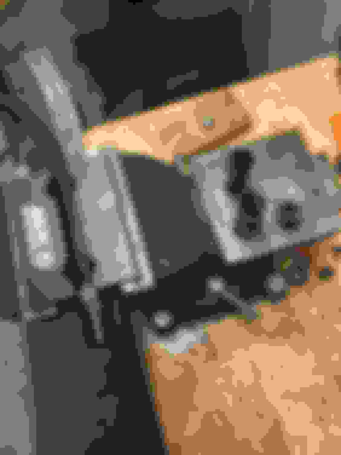
I have to run for now, but will continue the write up of the install on Friday. Here is a Teaser Pic of the engine bay, until then.
Well here is how I break down the tasks required to complete the installation.
1) Plan location of the FPR and the Filter. Create brackets to hold them.
2) Plan routing of the fuel lines, I believe there is more than 1 way to do this with the materials provided. I'll share mine.
3) Install hose ends, not too hard, but tedious, and you'll probably stick your finger tips with braided stainless wire at least once.
4) Assemble the entire system, route plumbing, mount rails, injectors, and tighten it all up.
5) Test system for leaks, and fuel pump function.
Since there are no instructions, I'll list the materials that come in the kit, and where I used them. Please see attached txt file. If your just reading to see what I did, don't bother with it, if your using this as a guild to help install you might want to print it and take it with you to the garage.
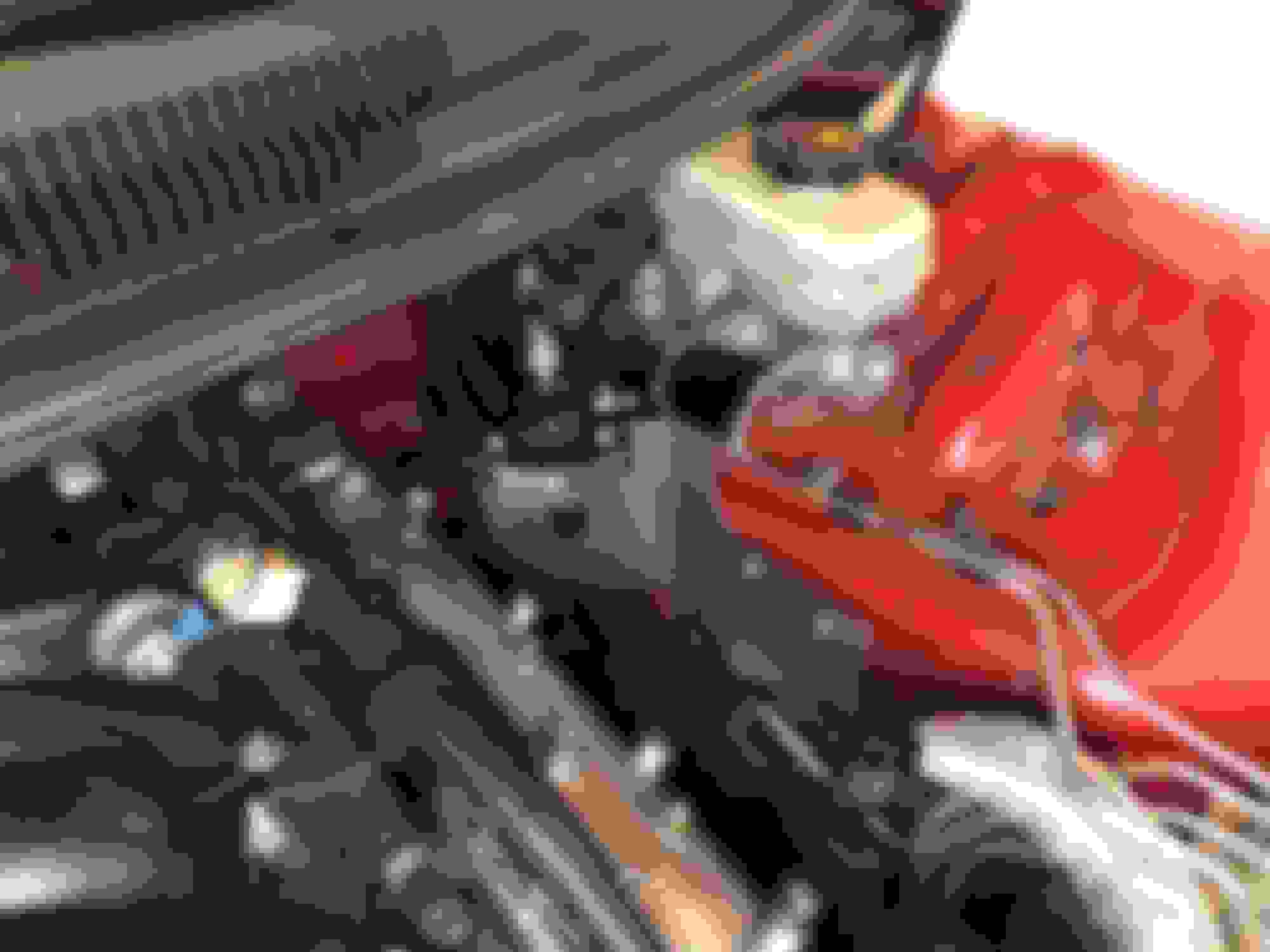
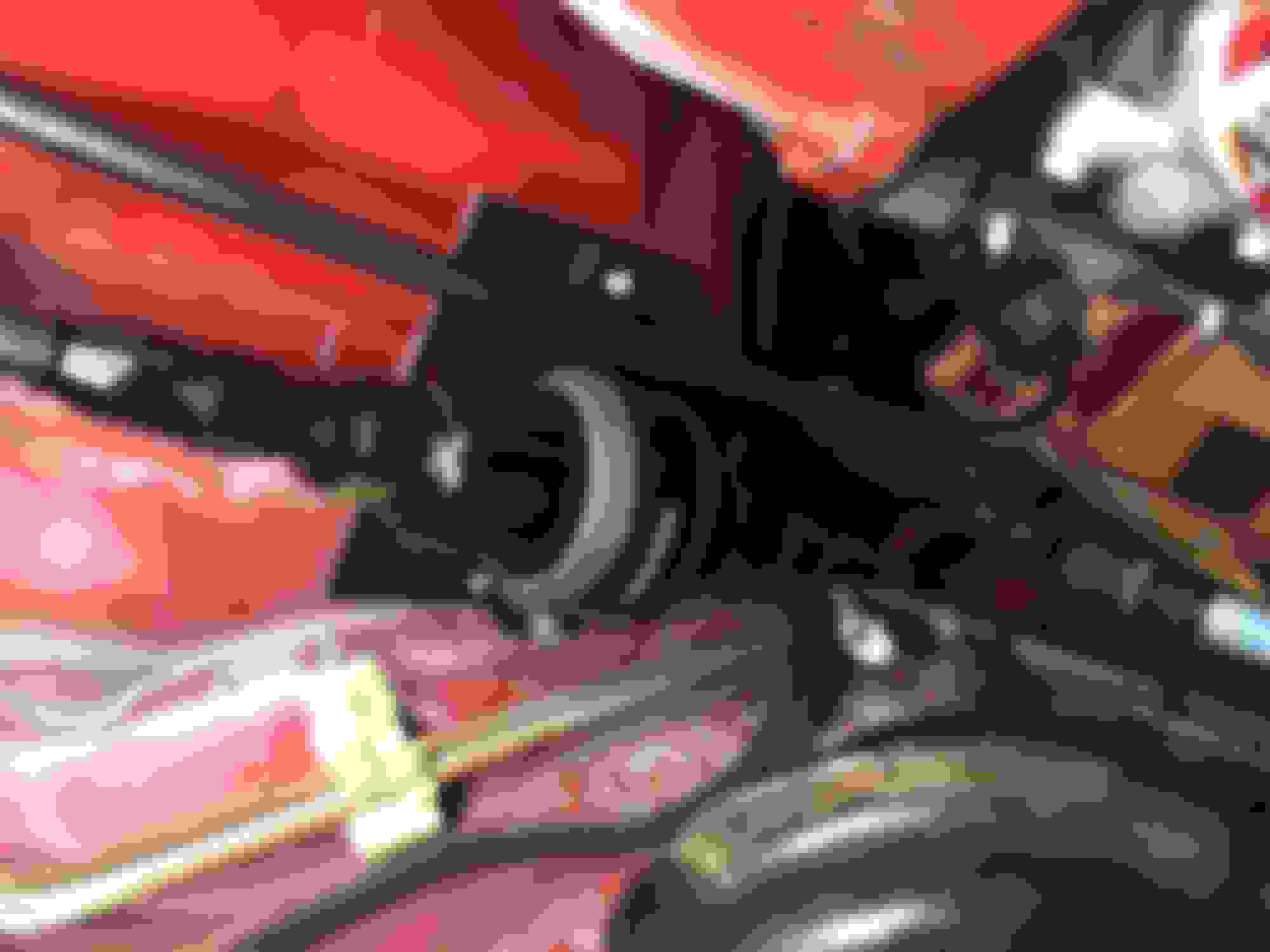
I wanted it high enough I could easily read the gauge, but still low enough for hood clearance, and I wanted it, and lines to and from it where they wouldn't get too much heat. I think I'm happy with where it is.
Filter Placement
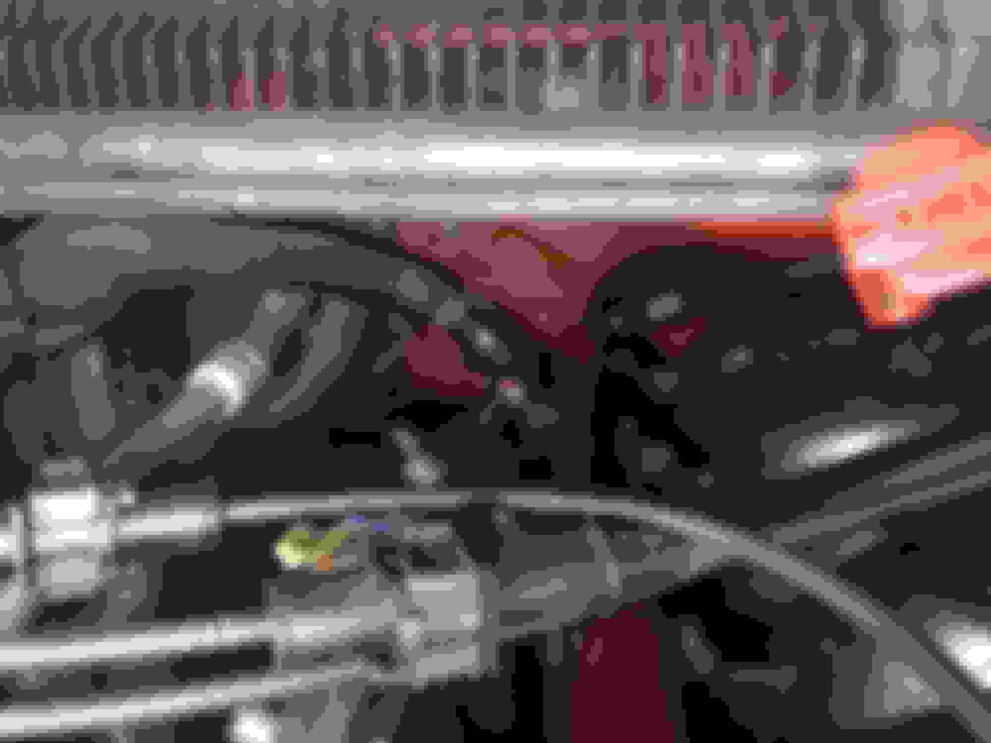
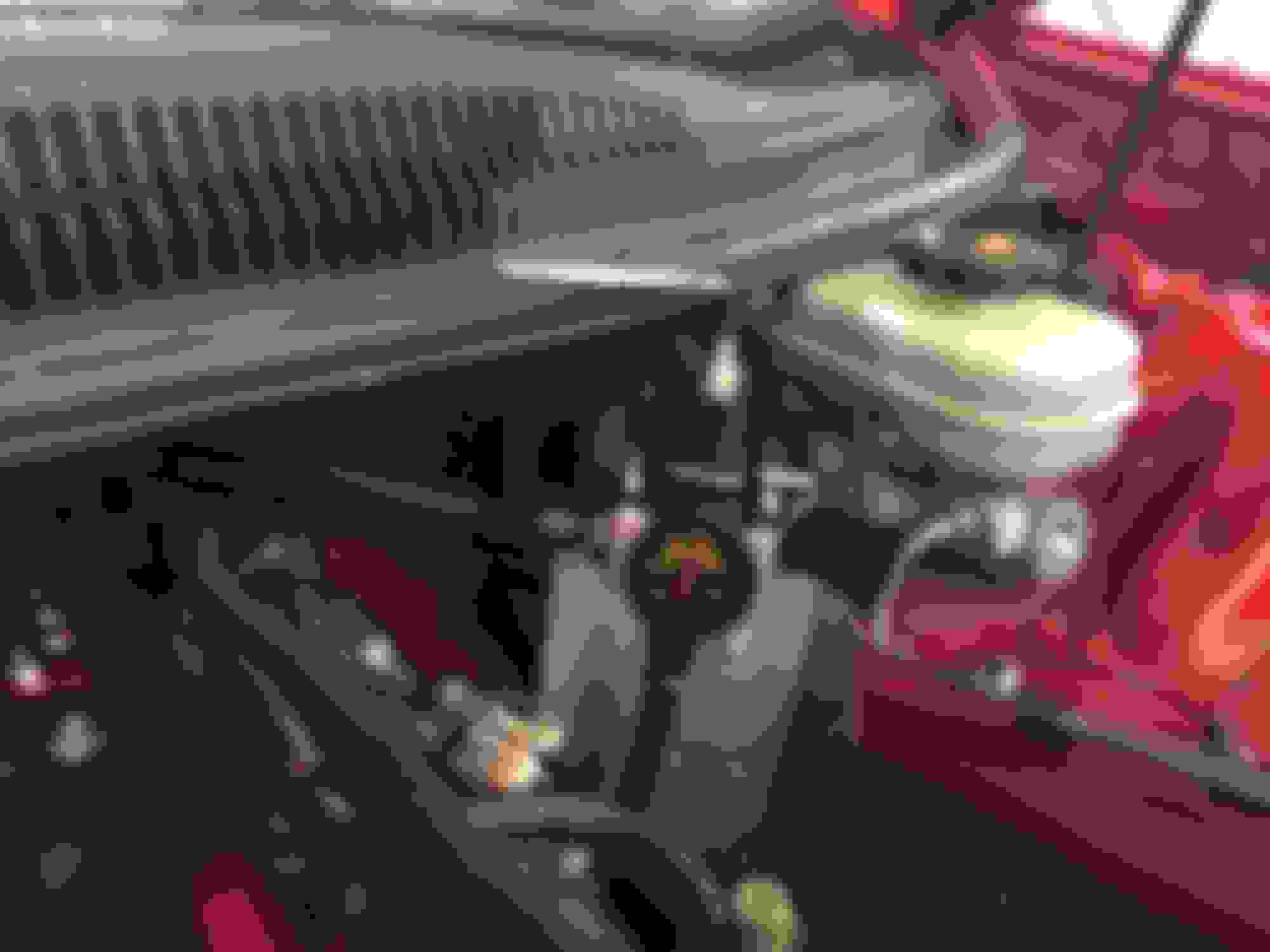
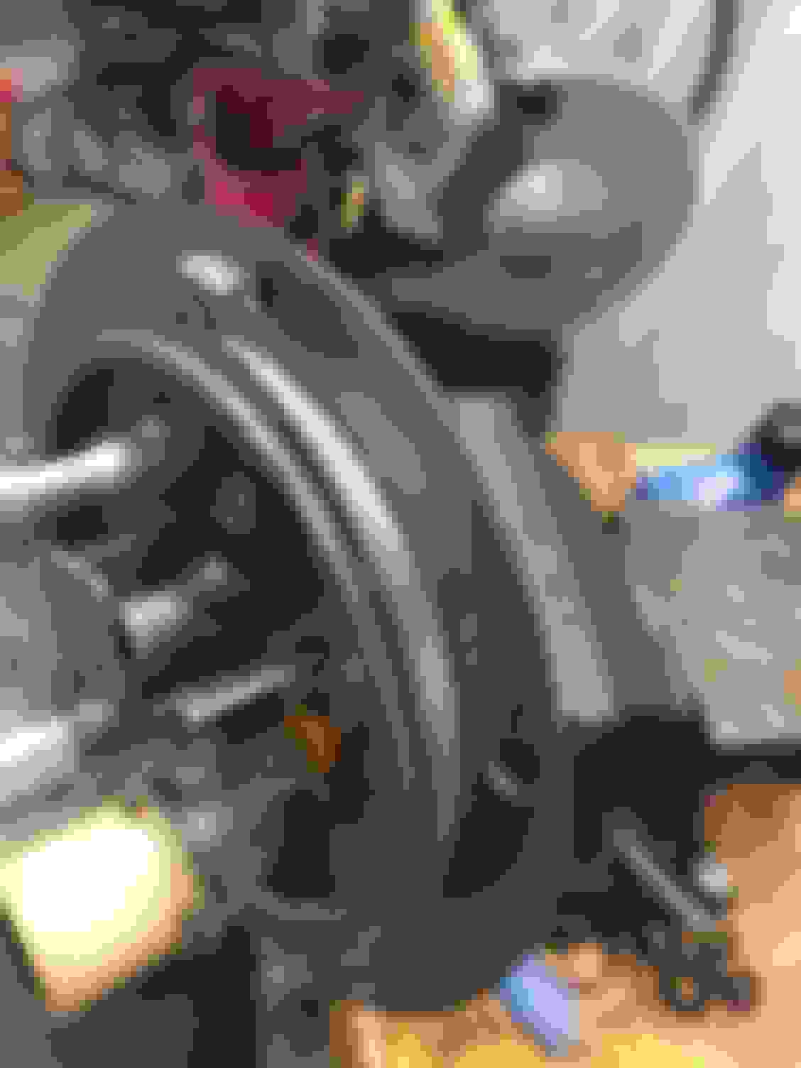
Next for me, since I've gone Turbo, all my exhaust will be down the passenger side of the car, the drivers side manifold goes forward, so it created a space where the driver side header collector was, when it was an H/C/I car. I wanted to use this space for something. I would place it at the rear of the car near where the original one was, if i did't have this space available.
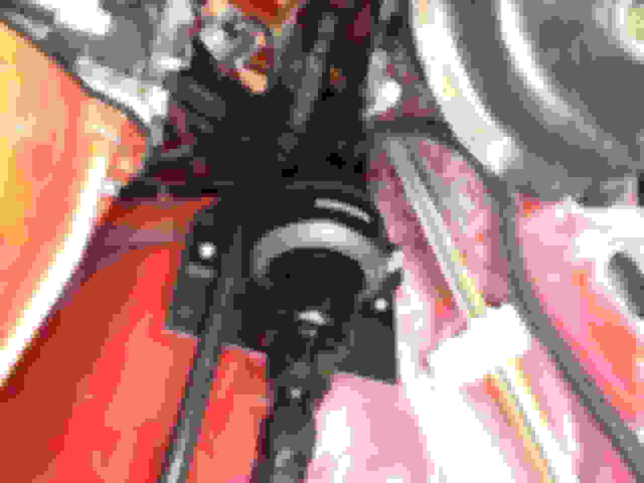
As you can see I ran the larger fuel feed outboard of the steering column, and the return inside, between the column and the exhaust manifold. I think this will work. There should still be plenty of clearance. The reason I did this was because, since the feed comes from the engine, it would want to drape across the manifold. The steering column holds it away. Since the bottom of the regulator is outboard of the manifold, where the return line comes from, there is nothing making it want to touch the manifold, so it can go strait down. You will need to make a small bracket up here to hold the filter housing like I did. Continued in next post.
I plan on boosting as well and this looks like a setup I want. what psi do you plan on and what hp rating are you going for, thus what size injectors are you going with I also plan on running e-85
1)Starting at the tank with -8 hose, and the larger of the 2 quick connect fittings, go to the Filter Housing, using the strait -8 female hose end into the -8 AN male/ -10 ORB adapter on the feed side of the filter housing. See the photos of the filter housing in the previous post, I won't bother repeating them.
2)From the filter housing through the second -8 AN male/-10 orb adapter, and a strait -8 AN hose end to the back of the drivers side fuel rail, using one of the -8 ORB 90 degree hose ends, on the rail end of the -8 hose.
3)From the front of the drivers side rail, to the front of the passenger side rail using 2 of the 90 degree -8 orb fittings and -8 hose.
4)From the back of the passengers side rail, using the 90 degree -8 orb/-6 male AN adapter, into -6 AN strait hose end, to the regulator, going into the regulator with another -6 AN strait hose end into the -6 AN male to -8 orb adapter.
Plug the other large -8 exit from the regulator.
5) From the bottom of the regulator, use the hose end with the strait -6 orb, on -6 hose, and run it all the way back into the return on the tank using the smaller of the 2 quick connect fittings supplied.
So you will have a total of 5 hoses. And 10 hose end installs. I'd take photos of them all laid out, but I put them in the car already, and a couple of them are a Pita. I would suggest you go and watch a few videos of installing PTFE hose ends with the olive, if you have not done this before.
You will need some tools.
You'll need a vice, and some inserts for doing AN fittings as well as a set of AN wrenches. I paid a total of $70 bucks for this set, the 5 wrenches -4 through -12, and the vise inserts. I have to do these 10, as well as power steering lines, and oil cooler lines for my transmission oil cooler, and turbo feed and return lines. A total of 22 hose end installations as part of my turbo install. It was worth buying these rather than making do with the standard wrenches, and the vise inserts I had, although they would work. I didn't even put a mark on any of the fittings, so I'm happy.
I also used a tubing cutter to trim back the Hytrel, I think that works well. I used a 7/16 wrench as a guide to determine how far back to cut the Hytrel, where I would have enough room to get the olive in, but still have the hose end cover all the braided portion.
Also I'd recommend getting a set of hose pliers, it makes it much easier to push on the quick connects. They are quite difficult to get on without them. They are much harder, and fit much tighter than my factory quick connects.
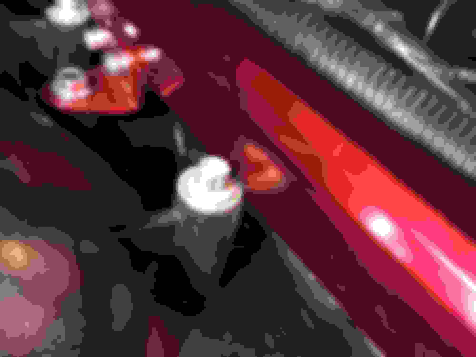
Here is what we have removed in the process. The factory fuel feed line, the filter, and the return line. The quick connect to the factory fuel rails, and the quick connects to the tank.
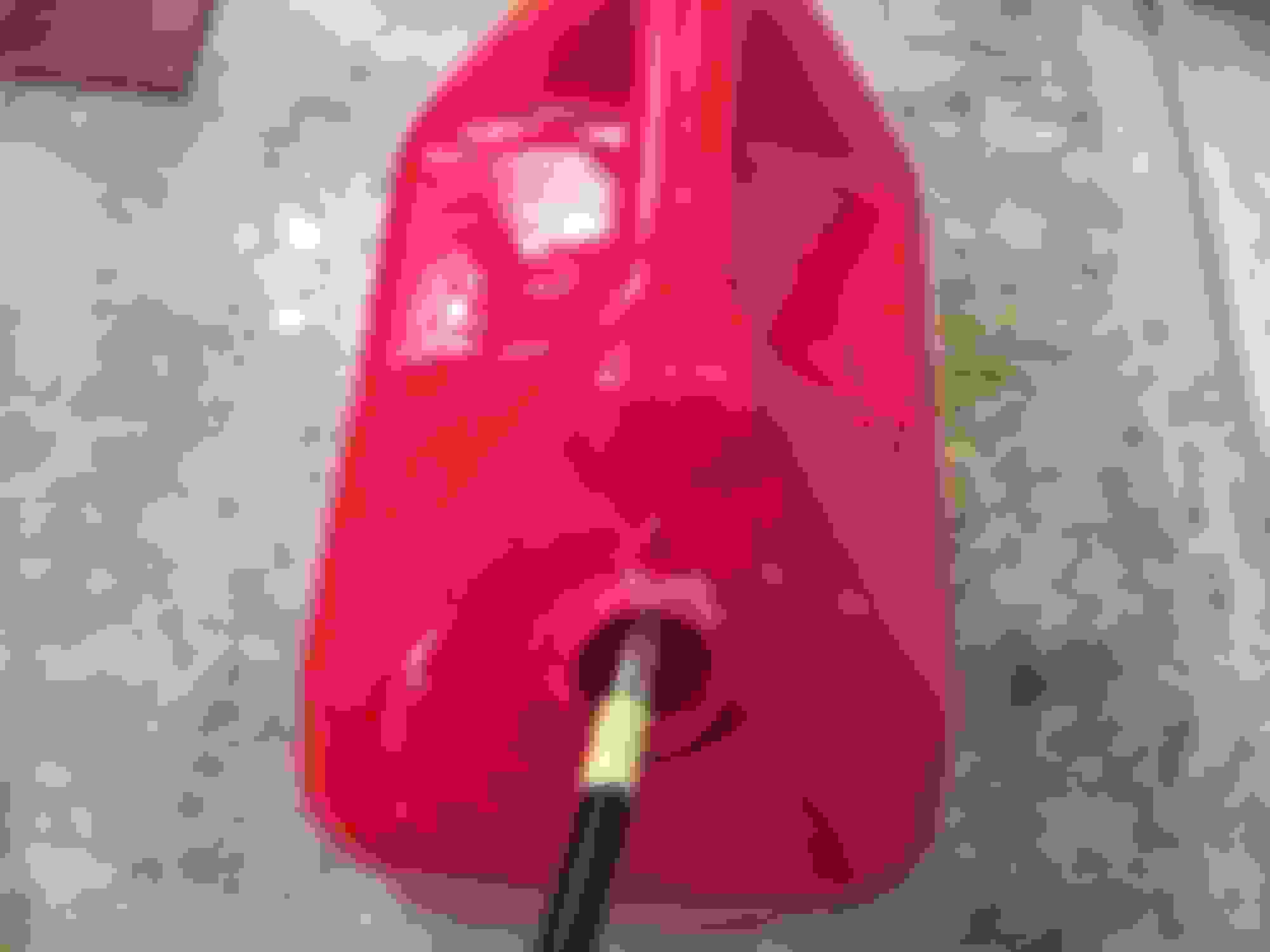
Well before I put the quick connect the return I decided to prime and test both pumps individually. I wired up some leads to the pumps from a 12v source individually. I tested them one then the other.
I ran the return line into a 5 gallon can and checked flow. I was blown away from the flow of each pump. I never ran them both together, because I only had 1 set of leads. It was like having a -6 fire hose. Honestly it seemed way more than 340 LPH I filled a 5 gallon can about as fast as you do at the gas pump when filling up. It seemed about a minute. I made a little mess to since it came out so fast.
I filled my riding mower!!
Next I would set my fuel pressure, factory the regulator was at 40 psi.
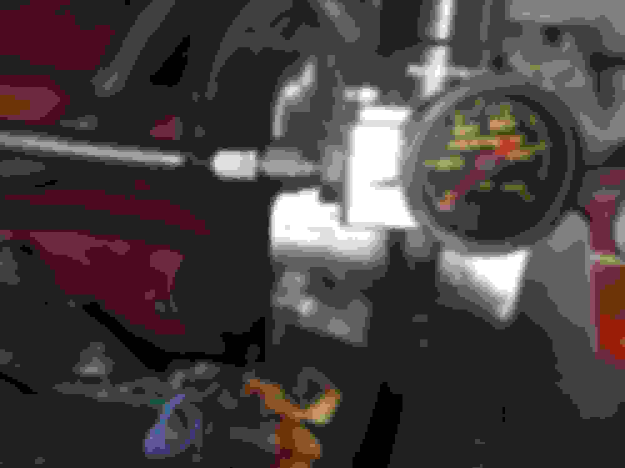
I bumped it up to 60 psi as base, then I'm going to run a vacuum line to it to boost reference. It took about 3 turns of the screw to get up to 60 psi, with a 3/16" allen wrench. Sorry the photo is a little out of focus.
Next I needed to check for leaks. All of my hose ends looked good, nice and dry. I did however have a leak at one of the fuel rails. I was leaking a little around the top of the #1 cylinder injector, where it meets the rail. The factory rails have clips here, aftermarket don't so this is a potential source for a leak.
It was not instantly obvious, it took a little while with the pump running, and a little fuel pooled on the intake by the base of the injector. It wasn't like anything was spraying out. It's important to go over the entire system with a flashlight, checking every possible point for a leak. I removed and reinstalled the fuel rail on the drivers side and it was fine. I put the rail on initially with the EV1 connectors on the injectors. I think maybe that's what caused the problem. I removed the connectors before installing the rail this time. After reinstalling the rail I reconnected the EV1 connectors to the injectors.
I still need to finish up the wiring, and put some cushion clamps on the lines under the car to hold everything solid. I'm probably going to use a boost referenced hobbs switch to bring on the 2nd pump. I don't have one yet so I'll need to order one. Maybe another week before I get around to that. I'll probably go back to working on other components of my turboization(my new word I just created) of car. I'll follow up with a later post once the wiring is done, and it looks nice and pretty.
I did purchase all of the components seen here from the WS6store. Trying to support 2 sponsors with my business. They were great, quick service, and you can actually talk to them. As far as Racetronix, they are good engineers IMO. They sell quality parts, and do things right. They do make a nice plug and play harness I could have used as well, but I saved over $100 making my own, from the 2 harnesses I already had. Basically I used 2 of their '98 hot wire kits, using a hobbs switch to trigger one of the relays, and the factory fuel pump circuit to trigger the other relay. Running 2 independent hot wires, one to each pump. I really wish Racetronix actually had customer service and understood it. It's a good thing their dealers do. I tried to contact them about upgrading my original Racetronix system, but they didn't make it easy. I had to join their forum, and that took a week etc. I came up with this idea here on my own using their parts. I have used their products for years, and the quality of their parts has earned my loyalty, so their components were an obvious choice for me.
In the end, it was more time consuming than I thought it would be, and I probably have a couple more hours to go, tucking up the wiring, and adding a few more cushion clamps on the hoses. I thought it would be something I could do in an afternoon, probably more like 2 days. That was partly because I needed to figure it out, then do it, not just do it. Economically it really is a win. There are other great sponsors here which have good stuff, and maybe easier to install. Comparably they are twice as much money. I have bought from these guys before and have respect for them, as I have received great service from them. One in particular has been great to me, answering questions etc. However at the end of the day it's hard to part with and extra $800, basically twice as much, to go with their systems.
The kit is not perfect, I'd put it together a little differently than Racetronix did, but they did pretty well. I'd use DW300 pumps, I just like them better, and I'd put a couple 45 hose ends where they went with strait ends. I'd also clearance the rails a little where they contact the intake. Maybe I'm wrong, but this system looks to be on par with the best of them out there, and pricing was very competitive. If you feel you have enough skillz to follow along and do this, I would recommend this system. I'd give it 4 of 5 stars.
Here is a tip for Racetronix, make a kit for people that are not such DIY type guys. Make some brackets to hold the filter and regulator, cut the hoses to length, and put the hose ends on them. Write some instructions, and throw in a plug and play harness. You could probably sell more of a finished kit for a lot more money, and reach more potential customers, because not everyone is willing, to do this much work. Some may not be capable? Keep this kit as well for those who are willing to do it, and want to save money.
I plan on boosting as well and this looks like a setup I want. what psi do you plan on and what hp rating are you going for, thus what size injectors are you going with I also plan on running e-85
I plan on going to the max the '98 computer will support with a 2 bar SD tune, which is 215 mPA. I'll work up there slowly. I have a bit of a crazy idea here as far as fueling goes. E65 to E75. The Speedway near my house has E85. They say it contains 51-83% ethanol. It typically tests about E70- E75. E65-E75 has almost the same knock resistance as E85, but will cool just a little bit less (slightly lower latent heat of vaporization compared with true E85). I intend to test every tank, and adjust the tune accordingly. If I get a tank that actually tests 85%, I'll add a gallon or 2 of 93 octane E10. For small variances I should be able to leave timing alone, keeping it a little conservative, and just tweak the Stoich ratio between tanks. I have an Alky Control meth injection system, which I'm also going to run. Even though I should have good knock resistance from the ethanol in the tank, there is still some value to being able to drop the IAT another 20-30 degrees from meth injection. This will add charge density, and power, possibly increase knock resistance a little further and maybe allow an extra degree or 2 of timing. It will also have a small contribution to fueling requirements. If I didn't already have a meth injection system, I would probably not invest in one. It does also allow me to set up a 93 octane pump gas tune as well if E85 goes away or is just unavailable someday. I'll probably not engage meth until at least 5-6 PSI. I'm running the DEKA 80 lb/hr at 3 bar, which will give 94 lbs/hr at a 60 psi base on the BRFPR. My calculations say that my fuel system should be able to support 900 HP at E75, Stoic = 10.39. This considers the injectors, the fuel pressure and the slight incremental fueling from injecting pure methanol. My engine made 402 rwhp, NA. At 15 lbs boost the theoretical max would be about 800, doubling NA output. We will not realize all of this because the exhaust system will not be as efficient trying to put that much exhaust through a turbine wheel then a 3" down pipe. I think 700-750 is a more realistic number, so I should have about 150 hp headroom on my fuel system. I've ran numbers on this way more than any normal person would. By profession I'm, a ChemEng with specialization in combustion engineering, so I've pushed this a little beyond the basics. However once this is set up it should be simple. Fuel up, test, tweak tune based upon a chart I've made up for various levels of ethanol content, which I'll carry in the glove box with the etOH checker.
A job well done! Thank you for spending the time to show you fuel system build. It will make my life a little easier when time for mine (have to order pumps and everything else), a good amount of work I really didn't think about until seeing it with the pictures and explanations you provided.
[QUOTE=ScottyBG;19444747]Here is the flow path of my hoses
1)Starting at the tank with -8 hose, and the larger of the 2 quick connect fittings, go to the Filter Housing, using the strait -8 female hose end into the -8 AN male/ -10 ORB adapter on the feed side of the filter housing. See the photos of the filter housing in the previous post, I won't bother repeating them.
Seems like a well thought out build and great attetnion to detail but I would swap those quick connects to the other design with the lock nut on it. Ive read that people have had those plastic ones come apart and catch fire and I personally saw one on a friends car that blew off on the track.
Thanks for the feedback jrpimp00, I appreciate you looking out for me. I just now learned that there was another type of quick connect, I went and researched them. It looks like the ones you are referring to are called "crescent lock". Too bad Racetronix doesn't put those in the kit I bought. After the time it took me to just get it buttoned up, its hard to be excited about tearing it apart and modifying it already. I did leave enough slack in the hose I could cut a couple inches off them and put new hose ends on if needed. As I was saying these quick connect fittings were much more difficult to install than the factory ones. Maybe just because they were new, and the Viton O-ring had never been compressed before. I couldn't actually push them on by hand since they fit so tight. I used those hose pliers I took the picture of to get them on. This was partly because they are in a bit of a tight spot. I'm sure I could put them on by hand out on a bench. That probably gave me a bit of a false sense of security regarding their ability to not leak.
I really did think about altering the top of the fuel sender to just mount a -8 male for the feed and a -6 male for the return. I think I could have pulled the metal lines out, and drilled a hole in their place and put in a bulkhead fitting with a 90 on it. That would actually cost only a little bit more than going with the quick connects, and I think would probably flow more.
Thanks again, I'll probably order the new style ends, and get them on when I get a few other things ironed out. It will only cost about $20 to change it.
I would like to start by saying that I have received a large number PM's, with both questions and suggestions. Questions about both about the Racetronix fuel line kit, as well as just general questions regarding setting up a boost referenced regulator, and putting plumbing in place to support it. Mostly from people who bought this same kit, but some people trying to put it together on their own, and doing some different things, like only running one line and using the factory feed as the other to save money. Looking at this there is a little money to be saved, but you don't get the full benefit of the flow capability of the whole system. If all it is ever going to be is a 650 whp car, then it probably doesn't matter. For the little bit extra this kit costs, I think it is well worth going the full monte so to speak. You get $100-$200 in rails, get $100-200 in a regulator, then your fittings, and enough line to run one way, and your really close to the cost of this complete fuel line, regulator and rail kit at about $550.
I don't know about you guys, but whenever I do something for the first time, I almost always look back at it and say I could have done some things differently, to make it better. Well I'm doing that here and going to make some changes before I even run the car. I could go with what I have, but I'd always say well I should have......
Concerns I had were 1) alignment of the fuel rails, I thought they should line up a little better, and 2) the piece of rubber fuel injection hose I used in the tank. I know that lots of people use fuel injection hose in the tank, but the OEMs don't. They use the plastic hoses designed for in tank use. Why, because they are more resistant to fuel, they are just better.
The other thing I learned about from this thread, was the locking quick connects from jrpimp00. I thought incorporating these into my system now made good sense.
I also learned that Racetronix, had a complete plug and play wiring system for '98s with dual pumps. I believe that this wiring system is used by at least one other sponsor on here for their dual pump kits. The ones that sell for like $600 plus. There are a few advantage to this over the way I had it wired using 2 hot wire kits. Its a cleaner install, 1 line instead of 2. It uses a bulkhead that is certified vapor proof. A grommet with a few wires passing through it is not. It activates the relays differently, my system turned the second pump on as long as there was boost in the manifold. On the Racetronix PnP system, the primary pump has to be activated, as well as there be boost in the manifold, to bring on the 2nd pump. The advantage of this is that if the hobbs switch were to fail to a closed state while the car was not running, it would run the boost pump until the battery was dead. On the Racetronix harness this would not happen because the primary pump circuit would not be active.
Well on to some photos showing what I did.
First the fuel rails. I notched them to give more clearance. This allowed me to get my injectors in a more strait up and down position. They were sealing I believe, but were not hitting the bosses in the intake manifold exactly perpendicular before this fitting. Afterwards they were. My notches are 0.020"-0.030" deep at the deepest points. Some areas needed a little more than others.
I actually contacted Racetronix about this, and got a response they were aware of it and were looking into it. They told me that they had tested them on and LS1,LS2, and LS6 intake and they were ok. On the Racetronix forum, there is at least 1 person other than myself that had this issue. It looks like it is variation in the intake manifolds? Maybe GM had more than 1 vendor for these things? Anyhow it was a very minor job to fit these thing to my intake. I'm happy with the fit now.
The next thing I addressed was the fuel tube inside the tank. On the original install, I gave up on getting the plastic tube to fit over the 3/8. Well I learned that you can buy these tubes expanded from Racetronix, for like $2.65. That is a win, expanding them yourself isn't easy. I figured out how to do it myself but buying it from them is easy. Anyone that wants to try it themselves, the way that worked for me was to heat the tube with a heat gun, like I use for shrinking shrink wrap, and threading a 3/8" bolt into the end of it while it is hot. The threads pull the bolt into the tube and expand it while its hot. Once it cools back the bolt out, and you have it. But it is way easier just to buy it that way from Racetronix.
Here is how the rubber hose looked when I pulled it out, it had sat in fuel for about a month, and already had softened and collapsed.
Here is the new fuel tube I ordered, I went 140mm long, it doesn't need to be that long, about 130mm would do it on my setup.
And here it is installed with Oetiker clamps, everything to OEM automotive standards. This hose will likely last longer in that tank than what I'll live, really.
Now here is jrpimp00's suggestion. Since I put this write up out there for 2 reasons, 1) to help others learn from what I did, and 2) a more selfish reason, to get feedback to help me. I'd be a fool not to listen and take action so here is what I did. I found the locking fittings on the Racetronix website and got some, for about $21 I may save myself a problem. The standard plastic locks are what the OEM's use but there is a better item out there.
I pulled my hoses back out and installed the crescent lock ones.
I just left the existing back nut on the hose and screwed in the new end into it without disturbing the lock that was there. Make it about a 10 minute job.
The last part of the install is installing the dual pump wiring harness. This is like the fuel line kit. It is a DIY kit, Racetronix does not support it with instructions or technical support. I think these things are really more intended for dealers, and people who sell dual pump kits to use as part of a product. Or just people that understand circuits, and are handy. The advantage to this is it is very affordable for what you get. Since it has no instructions, I'm going to do a separate detailed write up on how to install this harness. Expect to see it in the next couple days, on this thread. I'm going to try to get lots of pics and do the best job of writing it up I can. I hope to make it like the instructions that should have came with it. It is really a great solution, I'm really pleased that I went with it.
Well the new wiring system I got is the universal dual pump harness set up. The components installed include:
UDPH 005 the universal wiring harness
IDPH-F98 the intermediate harness for a '98 Fbody
and the HIH-001 the hobbs switch interface harness
All 3 of these components are required to make up a complete plug and play system.
This will replace the 2 harnesses that are currently on the car. Both of them Hotwire Kits, one for each pump.
Again the reason for doing this are simplifying to a much neater, more OEM/professional type of an install. This will also be a solution which is vapor proof, and all of the EVAP system is being maintained on the car, with full functionality.
Well to begin I needed to remove the wiring components, starting with the fuel pump assembly.
I started with cutting off the connectors I put on the ends of the individual fuel pump harnesses and run out through the grommet. Then onto removing the factory bulk head from the tank.
To remove the factory bulk head, you will need to start by removing the lock which holds the connector inside the tank to the bulk head, then pull the connector off.
I just twisted the ring off the bottom of it with some pliers. It did destroy it, but I don't think these things are really reusable. A new lock ring would be required to do so.
Next I needed to install the leads from the float level sending unit into the new wiring harness that goes inside the tank, that comes in the UDP 005 kit.
There are 2 areas in the connector that goes on the bulk head that are open, so these correspond to the areas that were used in my factory bulk head. So I transferred the connectors over into their same location on the new harness.
After that I put the lock in the connector and it is ready to go on the new bulkhead once it is mounted.
Next I need to plug the hole that I had made which I had the grommet through. I chose to do this with hex cap screw with an O-ring off an old fuel injector. It squeezed in there quite well, and I feel it is sealed up vapor tight.
You shouldn't have to seal this hole up, unless yours has been drilled for DIY dual fuel pumps like mine was.
Next onto installing the new bulk head that is included in the kit. The reason for the bulk head change is this one is rated for higher amperage than the factory one, to handle the increased current draw of the high volume aftermarket pumps. This is actually part of the intermediate F98 kit for 98 Fbodies. I believe there is a different bulk head in the 99-02 kits.
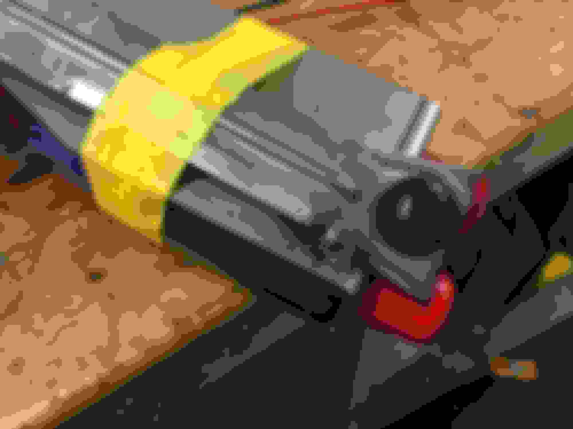
The bulk head presses into a ring on the underside like the factory one does. There probably is a special tool to put these together, but what I did worked well and was easy. I used a 7/16" socket and a wood clamp top press the ring onto the underside of the bulk head, I just kept screwing it until the bulkhead was well seated on its o-ring seal, and didn't wiggle anymore. Then I connected the in tank wiring harness to the bulkhead.
Then in needed to drill a 3/16 hole for the ground post to go through.
After that I installed the grounding post and attached the ground for in tank portion of the wiring harness, then it was done. This is how it looked with the ground post it, and both the pumps, and the sending unit wired in.
The bulk heads both have 4 connectors. The original factory set up used 2 for the level sending unit, one for the power feed to the pump and one for a negative lead, to the pump. The way this new bulk head works is that it uses 2 for the level sender, and 2 positives, one for each pump. The pumps both get their grounds, or negative side through the grounding lug mounted beside the bulkhead. The fuel pump assembly is now complete and ready to go back in the car.
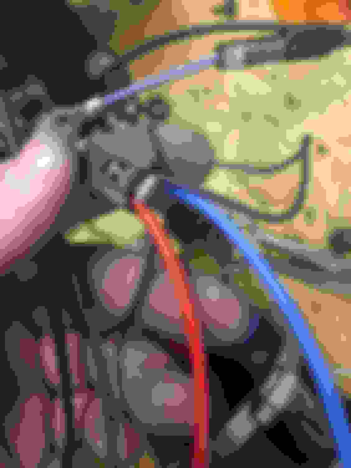
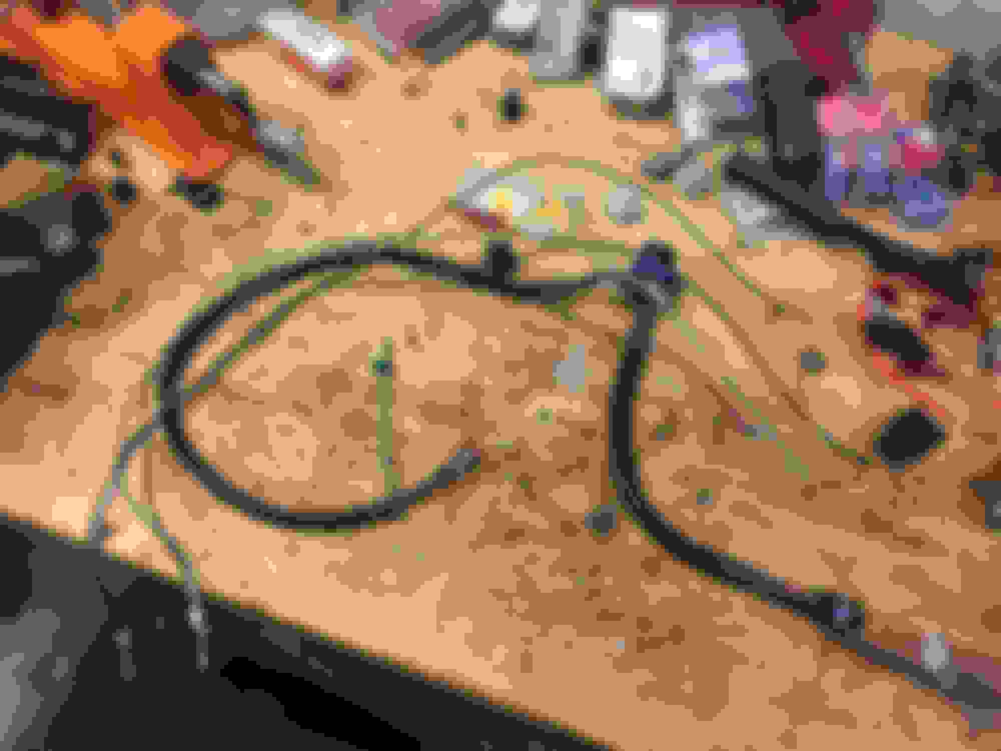
Next is on to wiring in the main wiring harness, I laid it out on the garage floor to get a look at it and get a vision of how I would install it.
It has a few ring connectors, and 2 fuses, one for each pump up at the front' as well this is where the hobbs switch harness connects to either the red or the blue circuit up at the front of the car, under hood. Both of the relays go at the back of the car, like where an original hotwire kit goes, if you have had one of those before. At the back end of the main universal harness it has a large round weatherproof connector where it interfaces with the model specific intermediate harnesses.
Well lets get started installing this main harness. We need to go to where the factory fuel pump circuit comes out on the body. This connector is found under the body, just above where the brake hoses that run to the rear axed attach to the body. My install is a little different because I had to start by removing my hot wire which was already connected here. Here is a photo of the connector I'm referring to.
This connector is labeled with letters A through H. The connectors we are concerned with are.
A- purple level sender wire
B - gray factory pump positive feed
C - black factory pump ground
F - Black stripe wire for level sender
The other 4 connectors we are not concerned with, 3 of them are for the Evap system, and 1 is not used, just leave them alone.
We do need to remove the factory wires, or the wires from the original hot wire kit (which might be in B and C if you have a hotwire) from the 4 locations mentioned above, A,B,C,F. See photo.
I then went ahead an removed these 4 wires from the factory harness. The intermediate harness will now be performing the duties of these 4 wires, so they are no longer needed. You should just have the 3 wires for the pressure sensor for the evap system left in the harness that runs from this block to the top of the tank.
Continued next post since this is getting pretty long.
After I got these wires out I compared them for length to the intermediate harness. Here you can also get a look at the intermediate harness itself. It connects to this block, the bulkhead on the tank, the ground on the tank, as well as the main universal harness through the large round connector.
Here is how the wires go into the block we just removed the factory ones from.
A - is the purple wire from the intermediate harness
B- gray wire from the intermediate harness
C- is not used anymore, the intermediate harness has its own ground
F- black wire from the intermediate harness
The back and the gray on the intermediate harness are for the fuel level sender, and the gray is the positive to activate the relays to make the large 10 gauge feed wires go hot.
So we go ahead and plug in these 3 wires into the factory connector in the locations listed above, and I blocked the C with a little piece of rubber I had. It is actually a specific piece intended to do this on a weather pack connector, but I'm not sure that is necessary.
Next we need to mount our relays close to here. I already had one mounted back here from the original hot wire kit so I was going to use that hole. I had to drill another hole, and I tapped it 1/4" 2- TPI and used a hex cap screw to hold on the relays.
I also attached the ground for the universal harness to one of the bolts holding the relays to the body. I covered this connection in dielectric grease, like I do all my grounds. The only other thing to do back here is to plug the large round connector into the intermediate harness. Then we run the harness along the underside of the body, zip tying it in various locations as we run the front up to under the hood. I kept mine all on the drivers side of the vehicle, and got my power and grounds up by the main fuse boxes.
Up here the red and blue ring connectors are on that positive stud, under a couple ring connectors I use relays for the aftermarket pusher fans needed for my turbo space. It is also convenient that this is near my vacuum block, for connection to the hobbs switch which is zip tied to the plastic fuse box holder, and is connected with a short piece of vacuum line, and a 1/8" NPT to a hose barb connector. Since it is so close to the universal harness I really only needed a hobbs harness about a foot long. I think this one is 6 feet, to I zip tied the excess and stuffed in in the hole by the fuse panel, under where that hood support is. That way if I ever want to move my hobbs switch I have the wire to do it. I have thought about drilling and tapping the intake manifold for a hobbs switch to screw directly into it some day.
So now we have the universal harness on, the hobbs harness on, and I still need to connect the intermediate to the tank. The intermediate harness is connected to the factory fuel pump connector, the one labeled A-H, and the large round connector on the universal harness. I actually lowered the tank a little to give me more room to work through the trap door. I just let the tank down a few inches to let it rest on the rear axle. This is no where nearly as difficult as "dropping the tank" in the case of doing this install from the bottom which requires completely removing the tank. Here it is up, showing the large round connector, then the second photo is it resting down on the axel housing.
This is how it looks from the trap door hole. This was not really necessary just to do the wiring, I had to get the fuel lines with the new crescent lock connectors onto the quick connects on the tank. In order to do that I needed to get a wrench on them so this space was necessary. It gave me an opportunity to get everything neatly sorted under there, no hoses crossing one another, etc.
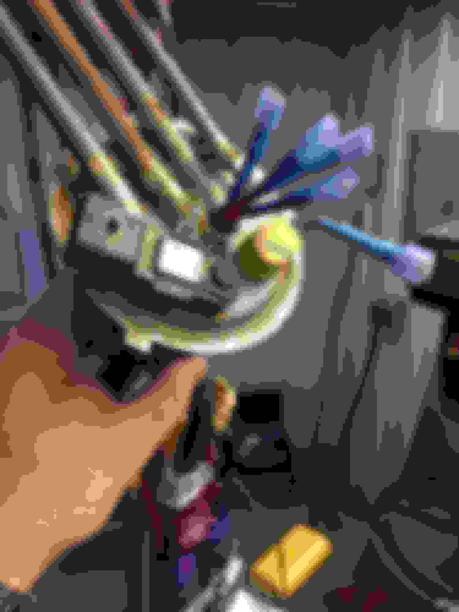
Even dropping this I needed to modify some wrenches so I could have enough space to turn them. I will say getting those ends to thread in was quite challenging, they kept wanting to cross thread, because the lines come in at a bit of an angle, and it makes the connector not want to be perfectly strait on the steel quick connect. See my dwarf tools.
Here are the new crescent lock connectors all snugged up on the tanks quick connects.
Next here is what the wiring looks like on the tank. The intermediate harness goes to the new bulk head. The factory line still goes to the pressure sensor for the Evap system. The ground from the intermediate harness goes on the grounding post. I zip tied the large round connector from the universal harness to the steel lines on the top of the fuel pump assembly to hold everything up in there neat. The other wires that run down go out to the factory fuel pump connector on the body by the relays.
Then I got all of the hoses, the 2 new fuel lines, the out and the return, and the 2 plastic evap lines run nicely through the channel that is stamped in the tank for them to run in, and put the factory foam back over the top of them to isolate them from rattling against the body when the fuel tank is in place. I got them all back just as the factory lines were run. You can only really see the return in the photo, the main feed line is under the 2 plastic evap lines.
Well that buttons it all up. The issues that I listed out have been addressed. The fuel rail alignment has been fixed by a little clearancing. The rubber hose in the fuel tank has been replaced with the proper plastic hose, with oeticker clamps. The plastic quick connect locks have been replaced with the metal screw in type. The 2 makeshift wiring harnesses have been replaced with the correct dual pump harness. I'm pleased that it's all done, and I'm really happy with the outcome. It looks very professional, safe, and I'm confident in the ability it has to be able to deliver fuel to my turbo motor. I'll update the thread with dyno numbers after I tune it. Any comments or questions?
Very nice! Your thread has been very informative plus the pm's we sent back and forth lead me to buying a complete dual pump fuel system from ws6 store. It was definitely worth the money, I got the whole fuel system a couple of days ago and the parts look like quality parts. I will continue to follow your thread to give me ideas to install the system. Thanks!
 11-02-2016, 12:09 PM