When you click on links to various merchants on this site and make a purchase, this can result in this site earning a commission. Affiliate programs and affiliations include, but are not limited to, the eBay Partner Network.
I have a L76 from a 2008 Pontiac G8GT with headers, Texas Speed Stage 1 cam and DOD delete kit from Texas Speed. Rest of engine is stock. It is in my 68 Lemans. after cam swap and re-ringing (engine had 30K on it) I have about 100 miles on it. I will drive for about 5-10 miles and when I park it I will get an 3" diam oil spot at the rear of the engine. I can see a drip from between the block and bellhousing. Nothing is coming down from the valley cover of above. It also leaks while driving because I have an oil film under the car. A person following said it is not burning oil. My first thought was that I did not get the rear cover and crank seal installed properly, but then I thought about my PCV system (or lack of) and thinking maybe I am building up crankcase pressure and it is pushing oil out through the rear cover. Is this possible? Following is what I did for the PCV system:
- From the passenger valve cover nipple ran a line from it to my intake tube ahead of the TB
- From the driver valve cover nipple I cap it off (I have also tried just leaving it open, came results, oil leak).
- Plugged the two inlets after the TB on the intake manifold.
There is no nipple on my valley cover from the DOD kit.
PCV problem or sealing problem?
If your losing oil and its not burning it then it's definitely leaking from somewhere. PCV systems do not flow oil they only ventilate the blow-by from combustion so if your seeing puddled oil then you sir have an oil leak.
So with the PCV system I have there is no way enough crankcase pressure could build to force oil out the rear seal or rear cover gasket assuming I installed correctly?
I doubt its PCV related based on what you've described is going on. If you've already confirmed its not the oil pressure sender or the valley cover then I'm thinking its leaking from either the backside of the oil pan, the rear main seal or the rear cover.
Thanks for the info. The assembly manual I used said to put RTV only at the bottom corners of the rear cover where it meets the pan and block. Looking on YouTube I saw some putting it across the bottom of the cover where it meets the pan. Is that possibly where I went wrong?
Thanks for the info. The assembly manual I used said to put RTV only at the bottom corners of the rear cover where it meets the pan and block. Looking on YouTube I saw some putting it across the bottom of the cover where it meets the pan. Is that possibly where I went wrong?
I don�t think that�s your issue. Pop your dipstick a little...just until o-rings are above the tube...so engine can breathe there, and go drive it. See what happens then. These LS engines just don�t leak oil unless they are worn out, or you installed something very wrong. Again, you need to move this to Gen4 External section please.
I will give that a try and see what happens.
I did post it on the Gen4 external section last night after I saw your message. No responses from that side yet.
I know with certainty, on the 5.0L Fords, excessive crankcase pressure can force oil past brand new front and rear crank seals.
If your Gen IV/G8 LS3 is plumbed like my crate LS3 -- the passenger side valve over nipple (with orifice) should be connected to the air inlet tube between the maf sensor and the throttle body. That way make-up air pulled into the crankcase via the valve cover is metered. Vacuum to the crankcase is applied by a little "U-shaped" connector right behind the throttle body. This allows intake manifold vacuum to "pull" on the crankcase. The orifice in the passenger side valve cover make up air connection limits air flow. Mine has been bone dry since day one.
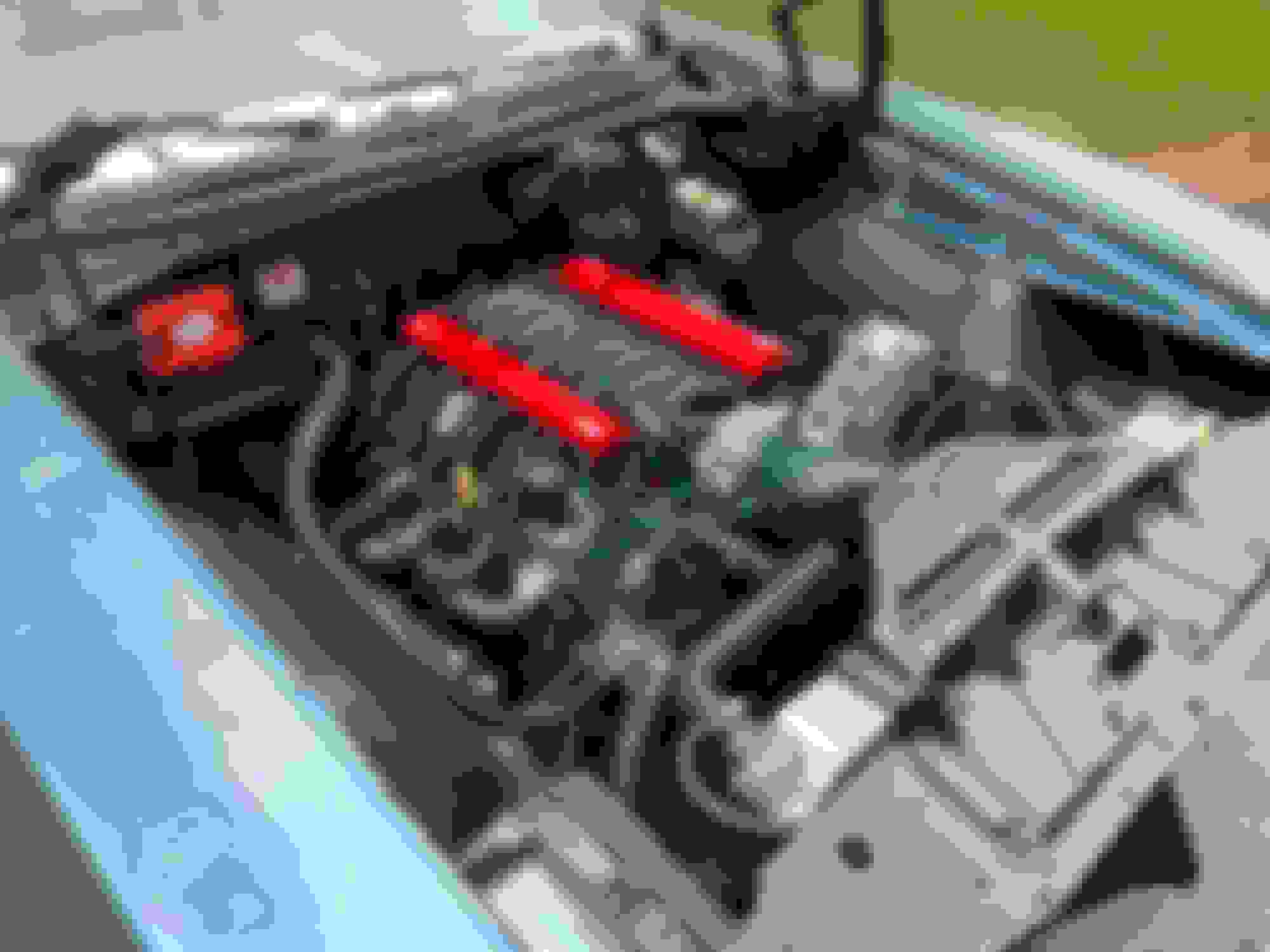
If you zoom in, you can see the "U-loop" just to the right of the valve cover oil filler cap. This connects intake to crankcase via the lifter valley. You can also see the hose connecting the passenger side valve cover nipple to the air inlet pipe.
Thanks for the Pic.. My passenger side is set up the same as yours, but I don't have a nipple for the "U" shaped line to the valley cover. See pics, zoom in to see my notes. Do I have an issue not having the nipple on the valley cover?
Near as I can tell - the only ventilation your crankcase has at all is through orifice-restricted passage in the passenger side valve cover INTO the air intake inlet. If that's correct, there's no manifold vacuum "pulling" on the crankcase at all. So you have no "PCV" arrangement at all. Seems to me you're likely to have crankcase pressure issues with the arrangement that I can see.
If both plugged ports in your picture are on the vacuum side of the throttle blade, I'd try connecting the one on the driver's side to the capped nipple on the driver's side valve cover. Then you have vacuum pulling on crankcase on the driver's side, and your "make-up air" connection on the passenger side.
If you wanna test the excessive crankcase pressure theory -- someone above suggested pulling up the dipstick until the o-rings AREN'T sealing. Clean up the bottom of the motor and then drive it for a while. That will let the crankcase vent through the dipstick tube. If the leak subsides, crankcase pressure was the culprit.
Yep, I saw the earlier dipstick suggestion and will try that first.
In regards to connecting the driver side valve cover to the vacuumed nipple wouldn't I need a PCV valve in the line? Otherwise i would have great crankcase ventilation but wouldn't it act like a vacuum leak? on a side note, my understanding is that the L76 G8 intake manifold is an LS3 intake (originally had a DBW throttle body on it). Based on this is there any difference in the passenger and driver side intake vacuum ports? They are different sizes.
Thanks everyone for the info so far. This is my first LS build and so far it want relatively well. I just need to get a few of these pesky problems solved and then I can enjoy the power!
In regards to connecting the driver side valve cover to the vacuumed nipple wouldn't I need a PCV valve in the line? Otherwise i would have great crankcase ventilation but wouldn't it act like a vacuum leak?
From my first response - �The orifice in the passenger side valve cover make up air connection limits air flow.� If the valve cover connections have the proper orifice in them, that eliminates the need for the traditional PCV valve. Mine idles at 650 rpm as smooth as a Honda and is consistently getting 19/20 mpg in town and 25-27 on the highway with no CEL�s or codes. No �vacuum leak�.
I�m drive by wire - no experience with your set up. Check valve cover nipples for presence of orifice....vague memory that that changed through the years. My OEM covers had them; my replacement Holley covers had them.
The OP does have the intake manifold pulling vacuum on the crankcase on the driver's side and he's running a line from the passenger side valve cover to the air intake bellow hence PCV. Is it restrictive due to the tiny orifice on the driver side valve cover? Perhaps but I don't think that's it either. He has an LS valley cover which has PCV built into it and it looks to me like its capped off. Connect the valley cover nipple to the intake manifold port or if you prefer put a sealed catch can between here to help slow up the amount of oil that could have reached the intake manifold. Then connect the passenger side to the throttle body or intake bellow. If still concerned install a small breather on the nipple on the driver side valve cover. That's how I would set it up if going PCV on your car.
#10 first picture he's showing the connection from the intake manifold to the back of the driver side valve cover and in the second pic he's showing the connection from the passenger side valve cover to the intake bellow.
If going PCV then he's missing the connection from the intake port from the driver side or passenger side "makes no difference" to the driver side rear valve cover. That is if the valve cover your using is the one with the small orifice in the line. If its the valve cover with the large hole on it then I'm pretty sure you install a PCV valve on the line between the valve cover and the intake manifold. Me personally I'd run 10AN lines of each valve cover to a breather can and call it good but that's me.

 07-22-2019, 06:55 PM