
My Custom Air Suspension Install - 99 Trans Am
 06-10-2009, 12:47 AM
#61
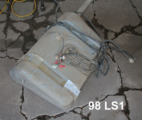
I want to get the fuel tank sorted out before I remove it. So far I've found some usefull info on a Datsun site of all places.
Here is a metal 98 tank just for comparison. As you can see, it's completly different from the later ones.

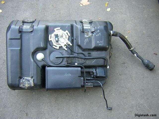
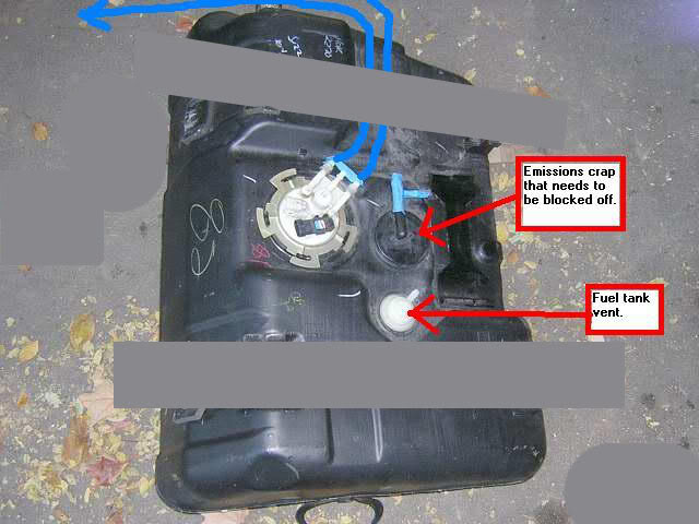
Here is what the 99+ model tanks look like.
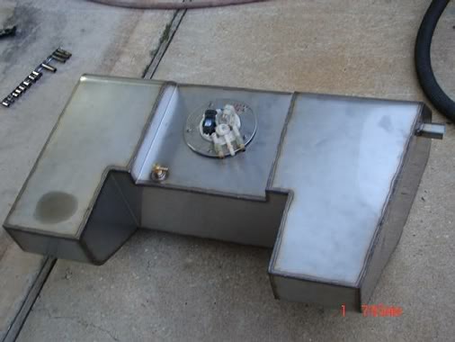
Here is Slammed1500's custom tank. I want my tank in the rear seat area so I want to use a fuel cell or have something made to fit.
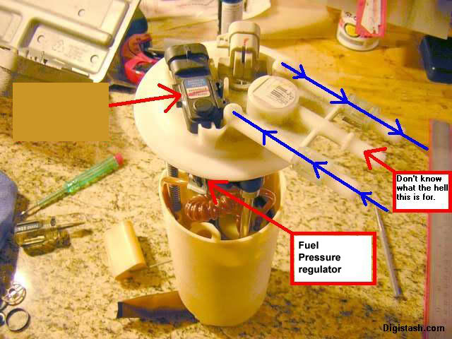
The stock pump and sender is just fine for me, so I want to copy how his stock fuel module was transplanted from the plastic tank to the new metal tank. If anyone has any more info on how are fuel systems work, please help me out.
Thanks.
Here is a metal 98 tank just for comparison. As you can see, it's completly different from the later ones.
Here is what the 99+ model tanks look like.
Here is Slammed1500's custom tank. I want my tank in the rear seat area so I want to use a fuel cell or have something made to fit.
The stock pump and sender is just fine for me, so I want to copy how his stock fuel module was transplanted from the plastic tank to the new metal tank. If anyone has any more info on how are fuel systems work, please help me out.
Thanks.
Last edited by JasonWW; 06-10-2009 at 01:07 AM.

 06-10-2009, 02:11 PM
#64
So do you think I should just cut out the black and white parts and include them in the new custom tank? That sounds like the best choice to me.
So only the fuel out and fuel return line are high pressure.
The other lines I can probably just use rubber fuel line and hose clamps.
Last edited by JasonWW; 06-10-2009 at 02:18 PM.
06-10-2009, 04:10 PM
#65
Here is the new diagram. Is this correct?
More facts:
The fuel level sending unit in the 98+ LS1 cars has a 70-240ohm range verses the tradidtional 0-90ohm range of the 93-97 cars.
The 98+ LS1 fuel level signal gets to the cluster via the PCM through the serial wire.
LS1 fuel level sending unit's positive (Purple wire to PCM) and ground (Grey to PCM ground).
Blue (230) Plug
A GRY PCM 46 5V Feed (Fuel tank pressure)
B Brown w/Stripe PCM 25 MIL Lamp Control
C WHT PCM 45 EVAP Canister Vent Valve Control
E Blue PCM 55 Theft Deterrent Fuel Enable
F DK GRN/WHT PCM 17 A/C Request
G GRY PCM 23 Fuel Level/Pressure Ground.
H DK GRN PCM 64 Fuel Tank Pressure
J PPL PCM 54 Fuel Level Input
K DK GRN PCM 58 Serial Data (Class 2)
Last edited by JasonWW; 06-10-2009 at 04:50 PM.
06-10-2009, 05:50 PM
#66
Here we go:
The Evaporative Emission (EVAP) Control system used on all vehicles is the charcoal canister storage method. This method transfers fuel vapor from the fuel tank to an activated carbon storage canister in order to hold the vapors when the vehicle is not operating. When the engine is operating, the fuel vapor is purged from the carbon element by intake air flow, and consumed in the normal combustion process.
EVAP System
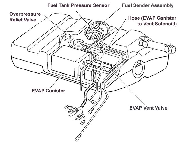
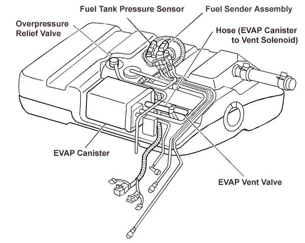
The evaporative system includes the following components:
• The fuel tank
• The evaporative emission canister vent solenoid
• The fuel tank pressure sensor
• The fuel pipes and the hoses
• The vapor lines
• The fuel cap
• The evaporative emission canister
• The purge lines
• The purge valve solenoid
The EVAP purge solenoid valve allows the manifold vacuum to purge the canister. The Powertrain Control Module (PCM) supplies a ground in order to energize, or purge on, the EVAP purge solenoid valve. The EVAP purge solenoid control is pulse width modulated (PWM), or turned on and off several times per second.
The EVAP canister purge PWM duty cycle varies according to the operating conditions determined by the mass air flow, the fuel trim, the engine coolant temperature, and the intake air temperature . For certain EVAP tests, the diagnostic will be disabled if the TP angle increases to more than 75 percent.
The evaporative leak detection diagnostic strategy is based on applying vacuum to the EVAP system, and monitoring for vacuum decay.
The fuel level sensor input to the PCM is used to determine if the fuel level in the tank is correct to run the EVAP diagnostic tests. To ensure sufficient volume in the tank to begin the various diagnostic tests, the fuel level must be between 15-85 percent.
The PCM monitors the fuel tank pressure or vacuum level via the fuel tank pressure sensor input.
The PCM monitors the vacuum level via the fuel tank pressure sensor input. At an appropriate time, the EVAP purge solenoid and the EVAP vent solenoid are turned on, allowing engine vacuum to draw a small vacuum on the entire evaporative emission system. After the desired vacuum level has been achieved, the EVAP purge solenoid is turned off, sealing the system. A leak is detected by monitoring for a decrease in the vacuum level during a specific time period, with all other variables remaining constant. A small leak in the system causes DTC P0442 to be set.
A restricted or blocked EVAP canister vent path is detected by drawing vacuum into the EVAP system. The PCM turns off the EVAP vent solenoid and the EVAP purge solenoid, with the EVAP vent solenoid Open, and with the EVAP purge PWM at 0 percent. The PCM monitors the fuel tank pressure sensor input. With the EVAP vent solenoid open, any vacuum in the system should decrease quickly unless the vent is blocked.
The Evaporative Emission (EVAP) Control system used on all vehicles is the charcoal canister storage method. This method transfers fuel vapor from the fuel tank to an activated carbon storage canister in order to hold the vapors when the vehicle is not operating. When the engine is operating, the fuel vapor is purged from the carbon element by intake air flow, and consumed in the normal combustion process.
EVAP System
The evaporative system includes the following components:
• The fuel tank
• The evaporative emission canister vent solenoid
• The fuel tank pressure sensor
• The fuel pipes and the hoses
• The vapor lines
• The fuel cap
• The evaporative emission canister
• The purge lines
• The purge valve solenoid
The EVAP purge solenoid valve allows the manifold vacuum to purge the canister. The Powertrain Control Module (PCM) supplies a ground in order to energize, or purge on, the EVAP purge solenoid valve. The EVAP purge solenoid control is pulse width modulated (PWM), or turned on and off several times per second.
The EVAP canister purge PWM duty cycle varies according to the operating conditions determined by the mass air flow, the fuel trim, the engine coolant temperature, and the intake air temperature . For certain EVAP tests, the diagnostic will be disabled if the TP angle increases to more than 75 percent.
The evaporative leak detection diagnostic strategy is based on applying vacuum to the EVAP system, and monitoring for vacuum decay.
The fuel level sensor input to the PCM is used to determine if the fuel level in the tank is correct to run the EVAP diagnostic tests. To ensure sufficient volume in the tank to begin the various diagnostic tests, the fuel level must be between 15-85 percent.
The PCM monitors the fuel tank pressure or vacuum level via the fuel tank pressure sensor input.
The PCM monitors the vacuum level via the fuel tank pressure sensor input. At an appropriate time, the EVAP purge solenoid and the EVAP vent solenoid are turned on, allowing engine vacuum to draw a small vacuum on the entire evaporative emission system. After the desired vacuum level has been achieved, the EVAP purge solenoid is turned off, sealing the system. A leak is detected by monitoring for a decrease in the vacuum level during a specific time period, with all other variables remaining constant. A small leak in the system causes DTC P0442 to be set.
A restricted or blocked EVAP canister vent path is detected by drawing vacuum into the EVAP system. The PCM turns off the EVAP vent solenoid and the EVAP purge solenoid, with the EVAP vent solenoid Open, and with the EVAP purge PWM at 0 percent. The PCM monitors the fuel tank pressure sensor input. With the EVAP vent solenoid open, any vacuum in the system should decrease quickly unless the vent is blocked.
Last edited by JasonWW; 06-10-2009 at 05:56 PM.
06-10-2009, 06:24 PM
#67
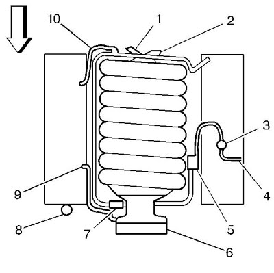
(1) To HVAC
(2) To Power Brake Booster
(3) EVAP System Test Port
(4) To EVAP Canister
(5) EVAP Canister Purge Solenoid
(6) Throttle Body
(7) Positive Crankcase Ventilation (PCV) Valve
(8) Exhaust Gas Recirculation (EGR) Valve
(9) Crankcase Ventilation Hose
(10) Crankcase Ventilation Hose
06-10-2009, 06:57 PM
#69
I'm not even sure what the whole air bagging thing is anymore.
You can:
1. Take a stock car and swap the steel springs with air springs and be done.
2. Leave the steel springs, but modify the car for more suspension travel.
3. Or do both.
The increased suspension travel I'm adding will let me have a lower ride height than anyone else while still keeping a smooth ride. I was going to do this with steel springs, but bags let you do a lot more. Such as lift the ride height for obstacles or drop it down for pictures. I don't have any fancy tanks or valves yet so I just air the springs up to ride height and I'm done.
I think the guys hopping their cars are a bit foolish. I'm not into that at all. Nor am I into driving real slow. I'm going to set the ride height low and haul ***!

I'm after the wicked cool stance of this Ferrari F430.

Last edited by JasonWW; 06-10-2009 at 07:03 PM.

 06-10-2009, 10:19 PM
#72
TECH Fanatic
iTrader: (1)
Join Date: Oct 2003
Location: Marrero/ New Orleans
Posts: 1,018
Likes: 0
Received 0 Likes
on
0 Posts

Here we go:
The Evaporative Emission (EVAP) Control system used on all vehicles is the charcoal canister storage method. This method transfers fuel vapor from the fuel tank to an activated carbon storage canister in order to hold the vapors when the vehicle is not operating. When the engine is operating, the fuel vapor is purged from the carbon element by intake air flow, and consumed in the normal combustion process.
EVAP System
The evaporative system includes the following components:
� The fuel tank
� The evaporative emission canister vent solenoid
� The fuel tank pressure sensor
� The fuel pipes and the hoses
� The vapor lines
� The fuel cap
� The evaporative emission canister
� The purge lines
� The purge valve solenoid
The EVAP purge solenoid valve allows the manifold vacuum to purge the canister. The Powertrain Control Module (PCM) supplies a ground in order to energize, or purge on, the EVAP purge solenoid valve. The EVAP purge solenoid control is pulse width modulated (PWM), or turned on and off several times per second.
The EVAP canister purge PWM duty cycle varies according to the operating conditions determined by the mass air flow, the fuel trim, the engine coolant temperature, and the intake air temperature . For certain EVAP tests, the diagnostic will be disabled if the TP angle increases to more than 75 percent.
The evaporative leak detection diagnostic strategy is based on applying vacuum to the EVAP system, and monitoring for vacuum decay.
The fuel level sensor input to the PCM is used to determine if the fuel level in the tank is correct to run the EVAP diagnostic tests. To ensure sufficient volume in the tank to begin the various diagnostic tests, the fuel level must be between 15-85 percent.
The PCM monitors the fuel tank pressure or vacuum level via the fuel tank pressure sensor input.
The PCM monitors the vacuum level via the fuel tank pressure sensor input. At an appropriate time, the EVAP purge solenoid and the EVAP vent solenoid are turned on, allowing engine vacuum to draw a small vacuum on the entire evaporative emission system. After the desired vacuum level has been achieved, the EVAP purge solenoid is turned off, sealing the system. A leak is detected by monitoring for a decrease in the vacuum level during a specific time period, with all other variables remaining constant. A small leak in the system causes DTC P0442 to be set.
A restricted or blocked EVAP canister vent path is detected by drawing vacuum into the EVAP system. The PCM turns off the EVAP vent solenoid and the EVAP purge solenoid, with the EVAP vent solenoid Open, and with the EVAP purge PWM at 0 percent. The PCM monitors the fuel tank pressure sensor input. With the EVAP vent solenoid open, any vacuum in the system should decrease quickly unless the vent is blocked.
i had 2 do all of my research the hard way it was a pain in the but 2 figure all that stuff out lol
06-10-2009, 10:24 PM
#73
I thought your tank making guy did all the figuring out. 
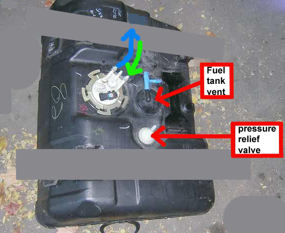
So is your brass fitting the vent?
Is it connected to the center of the 3 white tubes and then vented with a small filter or something?
Maybe we can figure out why your having filling problems.
So is your brass fitting the vent?
Is it connected to the center of the 3 white tubes and then vented with a small filter or something?
Maybe we can figure out why your having filling problems.
06-11-2009, 10:13 PM
#74
TECH Fanatic
iTrader: (1)
Join Date: Oct 2003
Location: Marrero/ New Orleans
Posts: 1,018
Likes: 0
Received 0 Likes
on
0 Posts
i had 2 figure it all out
yes the brass fitting is my vent
i have a T inline for the charcoal canister and the pressure relive valve
it just needs a bigger vent
or another vent add in
and for the relive valve i used the one off of the 98 tank it snaps on the frame rail
u can see it in the pic u posted........ its the white thing on the end of the hose
i have the part # at the shop if u need it
 06-14-2009, 05:24 PM
#76
After reading a lot of tales of electric valves sticking and such, I decided to get a hold of some manual valves and run 1/4" lines to the bags. So far I've found 2 types of valves that will work.
These are the common plastic paddle valves with 1/4" barbs on the back for the hose. Very restrictive.
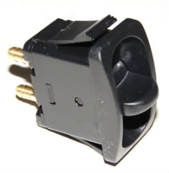
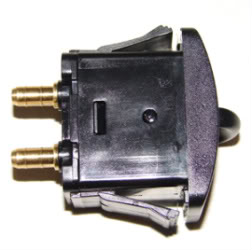
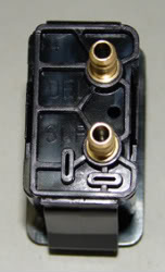
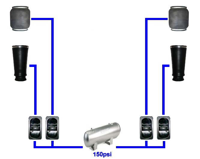
This is the Clippard FBV-3MPF. It's made of brass and has 1/8" NPT threads. It should flow much more than the plastic paddle valve above. One potential problem is that it's rated at 120psi. They do make similar looking valves rated at 150psi.
http://www.globalspec.com/FeaturedPr...00/0?deframe=1
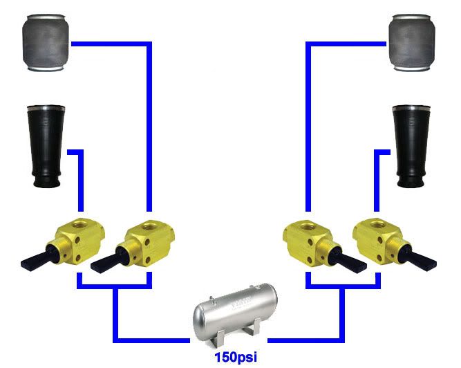
Features
• Rugged Delrin� toggle for easy operation.
• Mounting threads for panel or two holes for
surface mounting.
• Bright dipped brass construction for long life
and corrosion-resistance.
• Stainless steel springs, Delrin� toggle and
spools—non-corrosive.
• Buna-N seals; Viton� option available.
These are the common plastic paddle valves with 1/4" barbs on the back for the hose. Very restrictive.
This is the Clippard FBV-3MPF. It's made of brass and has 1/8" NPT threads. It should flow much more than the plastic paddle valve above. One potential problem is that it's rated at 120psi. They do make similar looking valves rated at 150psi.
http://www.globalspec.com/FeaturedPr...00/0?deframe=1
Features
• Rugged Delrin� toggle for easy operation.
• Mounting threads for panel or two holes for
surface mounting.
• Bright dipped brass construction for long life
and corrosion-resistance.
• Stainless steel springs, Delrin� toggle and
spools—non-corrosive.
• Buna-N seals; Viton� option available.
Last edited by JasonWW; 06-14-2009 at 07:19 PM.
 06-14-2009, 07:28 PM
#79
I'm looking for manual, not electric. Don't buy anything from that store. They are a part of AIM and those valves are known to leak or stick. If you go electric, I would get the best you can. Don't cheap out on them. Run water traps, too.
Last edited by JasonWW; 06-14-2009 at 07:34 PM.
06-14-2009, 07:54 PM
#80
TECH Fanatic
iTrader: (23)
Join Date: Feb 2008
Location: Los Angeles, CA
Posts: 1,838
Likes: 0
Received 0 Likes
on
0 Posts
did you ever think if removing the e brake and installing a line lock and just locking the front breaks? is that possible when the car is off? i mean for the line lock to still be working