


Having troubles with LED's
I want to wire up a led that will be on when my fan switch is on. I have my fan switch set up like so.
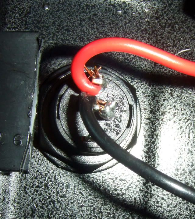
the red wire is coming from the PCM harness, and the black wire goes to ground, when the switch is on, it just grounds out the fan and turns it on. I want the led to be on when the switch is open. ( I already have the led, tried to see what it was and the only thing I could get was where the led was on when the fan was off, that was by putting the long lead of the led on the red wire, and the short lead on the unused terminal on the switch )
any clues on how to wire this up? I also tried going between the red and black wires but that just turned the fan on and let the led haha.
TIA

TECH Addict
Joined: Sep 2006
Posts: 2,591
Likes: 1
From: Massachusetts
Don't you want it on when the switch is closed then? If so, just put it in series. Might want to put a resistor in parallel
Edit to note: Technically, it's better to use a transistor (or if you're a car guy that didn't take any regular electronics courses, RELAYS SOLVE EVERYTHING MAN!) but the current here should be low enough that my earlier reply stands
Edit to note: Technically, it's better to use a transistor (or if you're a car guy that didn't take any regular electronics courses, RELAYS SOLVE EVERYTHING MAN!) but the current here should be low enough that my earlier reply stands
Last edited by dragonrage; Sep 14, 2006 at 06:03 PM.
So when you say put it in series, I don't understand, doesn't one lead off the led have to go to the positive, and one to negative? Or would it work If I put the led in line on the ground side?
TECH Addict
Joined: Sep 2006
Posts: 2,591
Likes: 1
From: Massachusetts
If you put one lead on the positive and one on the negative, you are effectively bypassing the switch - current will always be allowed to flow through the LED. Not to mention you would short out (turn off) the LED when you turned on (closed) the switch.
You have to cut a lead and put the LED in. Doesn't matter which lead you do it on as long as the LED is oriented correctly.
You have to cut a lead and put the LED in. Doesn't matter which lead you do it on as long as the LED is oriented correctly.
Alright, I just put the led in, I put it in line with the ground ( cut the ground, put one part of the ground wire off the switch onto one led lead, then the rest of the ground wire I connected to the led lead. I hit the switch and now nothing happens.. the power wont flow through the led, but if I put a jumper onthe led leads, To by pass it, it works.
If I need a resistor or relay just tell me..
If I need a resistor or relay just tell me..
Teching In
Joined: Nov 2005
Posts: 29
Likes: 0
From: Ft Walton Beach, FL
Connect the ground of the LED to the red wire on your switch, just tap into the wire. Then take the positive of the led and connect it to a 12v power source. Now when you turn the switch on, the red wire should be getting a ground and your led will turn on. Keep in mind though that if it's not a 12volt led you will need to wire a 10k resistor inline with the power wire (in series).
Trending Topics
LS1 Tech Stories
The Best V8 Stories One Small Block at Time

Topdon ONE vs. Artidiag 800 BT2: Which is the Diagnostic Tablet For You?
Pouria Savadkouei
Gas Monkey Built a 6-Wheel Ferrari Testarossa With a Corvette LT4 Engine
Verdad Gallardo
7 Most Reliable High-Performance Engines GM Has Ever Built
Verdad Gallardo
Amazing '71 Camaro Restomod Is Modern Muscle Car Under the Skin
Verdad Gallardo
6 Common C5 Corvette Failures and What's Involved In Repairing Them
Pouria Savadkouei
Retro Modern Bandit Pontiac Trans AM Comes With Burt Reynolds' Autograph
Verdad Gallardo
Top 10 Greatest Cadillac V Series Performance Models Ever, Ranked
Pouria Savadkouei
Top 10 Most Powerful Chevy Trucks Ever Made!

Hennessey's New Supercharged Silverado ZR2 Has 700 HP
Verdad Gallardo
Originally Posted by Sgt Joe
Connect the ground of the LED to the red wire on your switch, just tap into the wire. Then take the positive of the led and connect it to a 12v power source. Now when you turn the switch on, the red wire should be getting a ground and your led will turn on. Keep in mind though that if it's not a 12volt led you will need to wire a 10k resistor inline with the power wire (in series).
Like this?
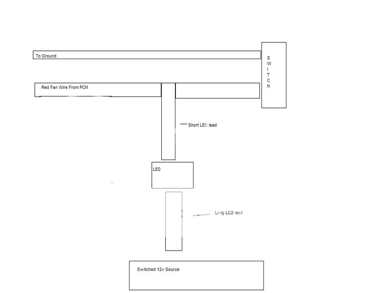
with the resistor inbetween the source and the led?

Launching!
Joined: Mar 2005
Posts: 297
Likes: 1
From: Chicago
The reason for the resistor is to limit the current flowing through the LED. LED's have a rating, usually in mA. 10K might be too high, 1K might be more inline. Use ohms law to figure out what resistor you need to use based on the requirements of the led (R=V/I , where V is 13.8V and I is current).
If you use no resistor, your led will light up for a second, then fry
If you use no resistor, your led will light up for a second, then fry