

V12 LS1 Build
 03-21-2015, 01:40 PM
#581
11 Second Club
iTrader: (14)
Join Date: Mar 2008
Location: Houston
Posts: 1,434
Likes: 0
Received 0 Likes
on
0 Posts

I'm glad it's back as well. Don't see in-depth custom stuff like this very often.
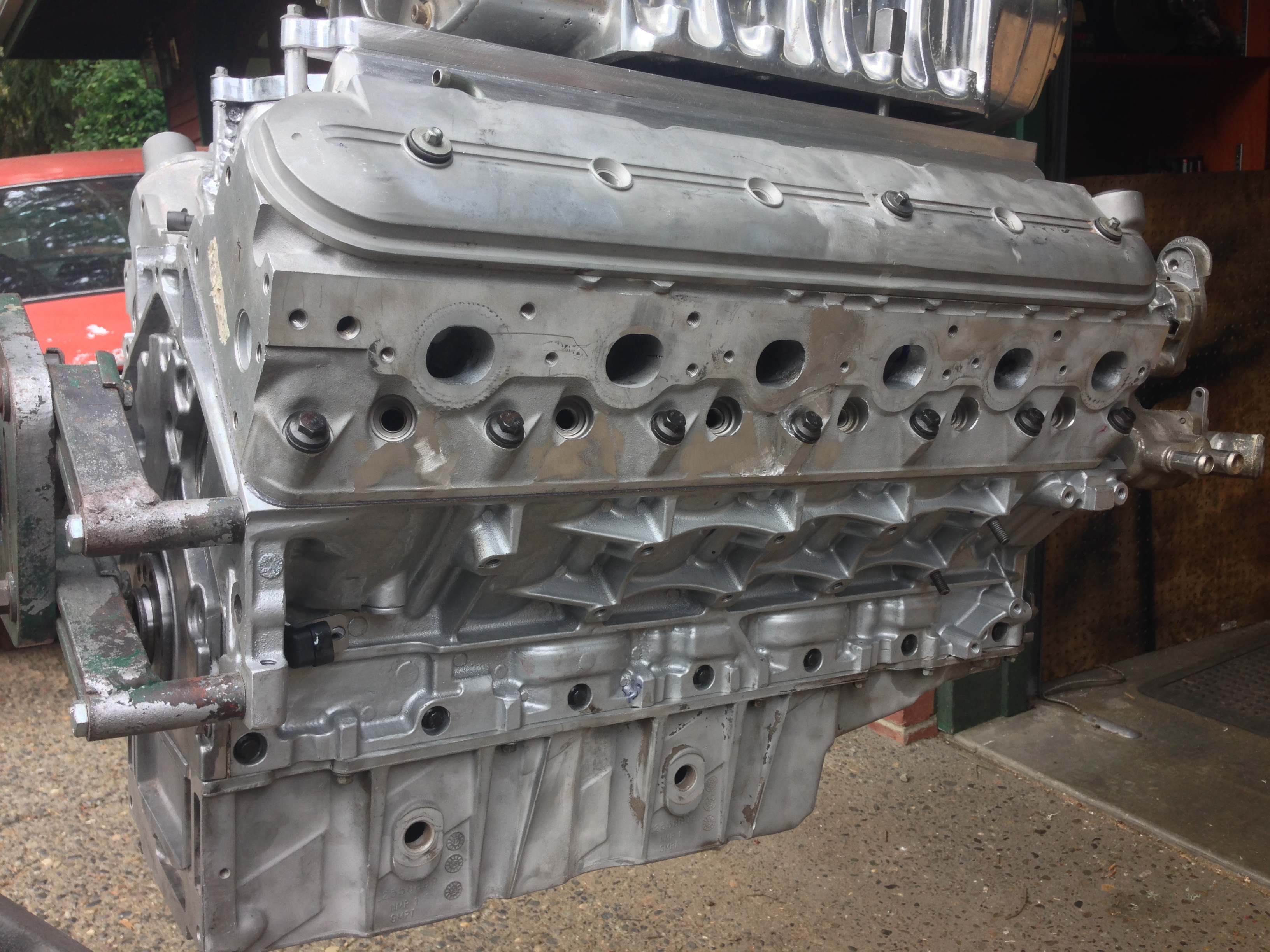
Curious though, are you not worried about heat issues with the center cyls? One of them has no coolant ports at all. I would think that would cause some cooling problems, especially with boost.
Curious though, are you not worried about heat issues with the center cyls? One of them has no coolant ports at all. I would think that would cause some cooling problems, especially with boost.
 03-21-2015, 09:04 PM
#582
Staging Lane
Thread Starter

Join Date: Apr 2013
Location: Seattle, Washington
Posts: 53
Likes: 0
Received 0 Likes
on
0 Posts
I'm glad it's back as well. Don't see in-depth custom stuff like this very often.
Curious though, are you not worried about heat issues with the center cyls? One of them has no coolant ports at all. I would think that would cause some cooling problems, especially with boost.
Curious though, are you not worried about heat issues with the center cyls? One of them has no coolant ports at all. I would think that would cause some cooling problems, especially with boost.
 03-21-2015, 11:29 PM
#583
11 Second Club
iTrader: (14)
Join Date: Mar 2008
Location: Houston
Posts: 1,434
Likes: 0
Received 0 Likes
on
0 Posts
Please don't take any of this negatively, yours is actually one on the most interesting LS related projects I've ever seen. I'm just trying to better understand how it's going to work.
 03-23-2015, 09:40 PM
#586
Staging Lane
Thread Starter
Join Date: Apr 2013
Location: Seattle, Washington
Posts: 53
Likes: 0
Received 0 Likes
on
0 Posts
I guess I'm still a little confused. What about the head? If I'm understanding you right, the cylinder that appears to have no cooling ports actually has the ports under the solid surface, is that right? If so, how is the coolant circulated in those ports? And how is the head cooled for that cylinder?
Please don't take any of this negatively, yours is actually one on the most interesting LS related projects I've ever seen. I'm just trying to better understand how it's going to work.
Please don't take any of this negatively, yours is actually one on the most interesting LS related projects I've ever seen. I'm just trying to better understand how it's going to work.
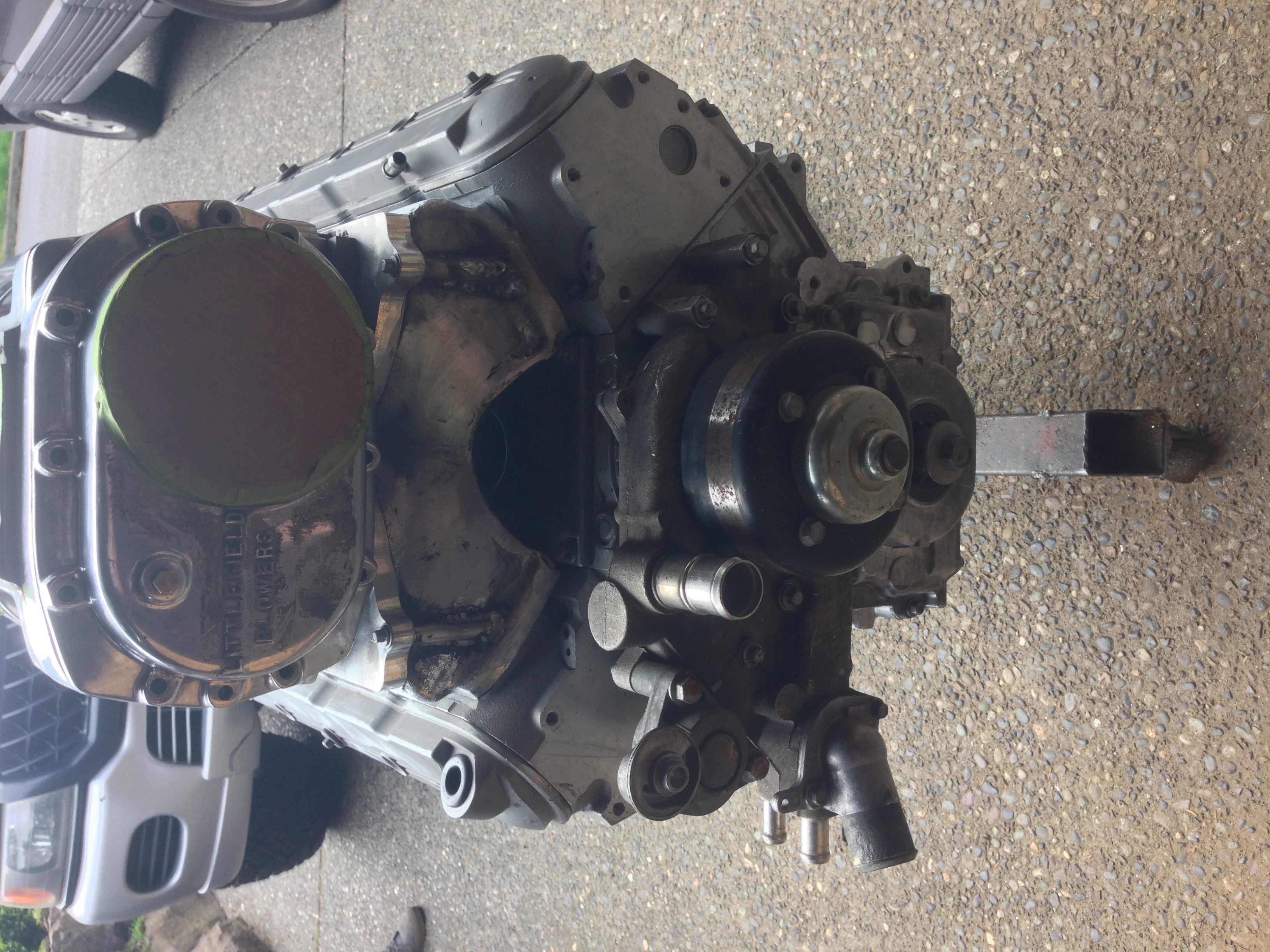
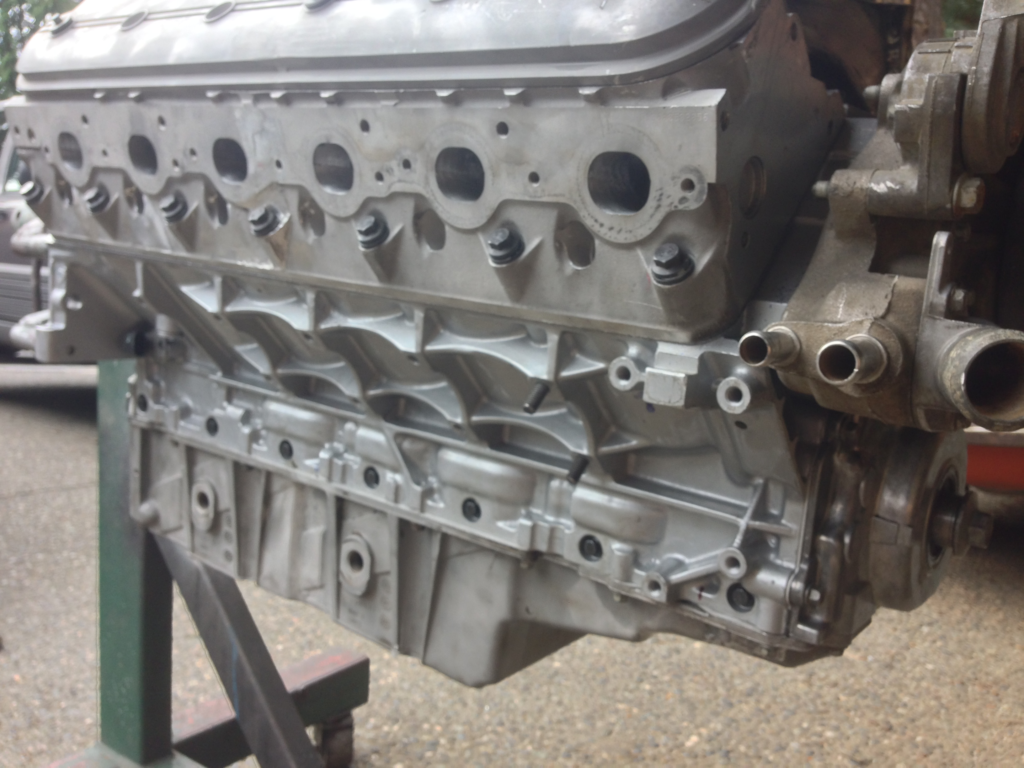
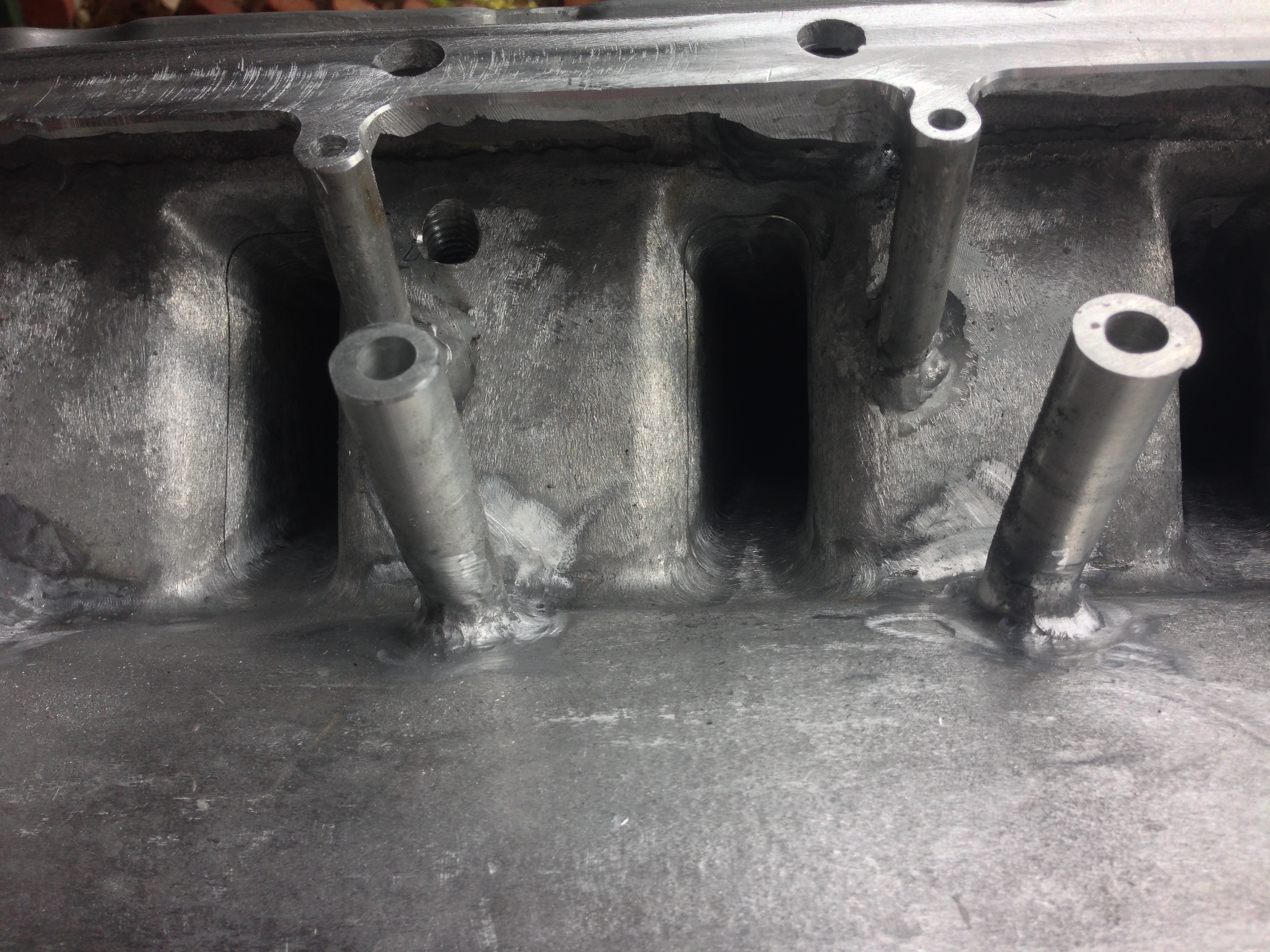
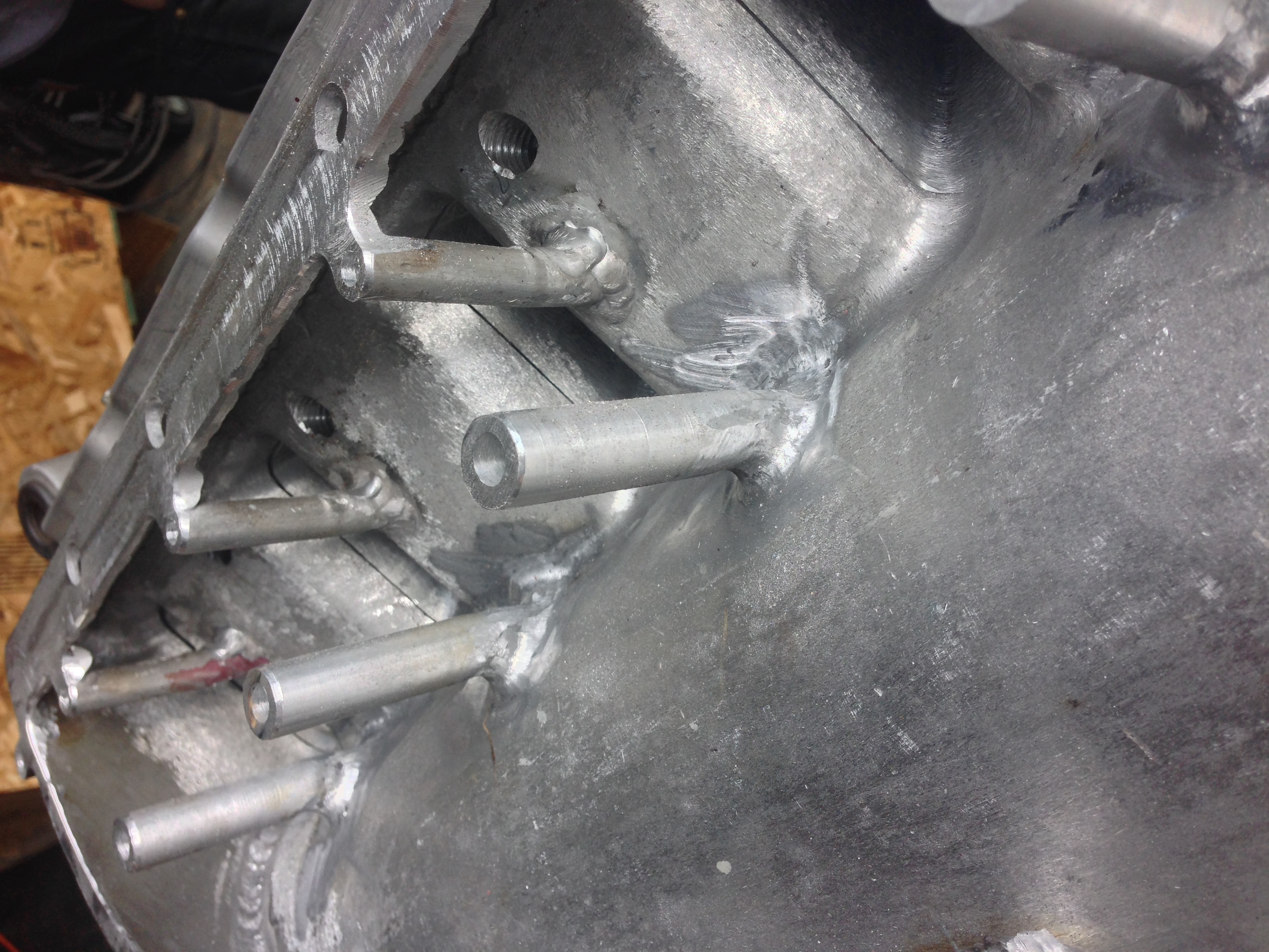
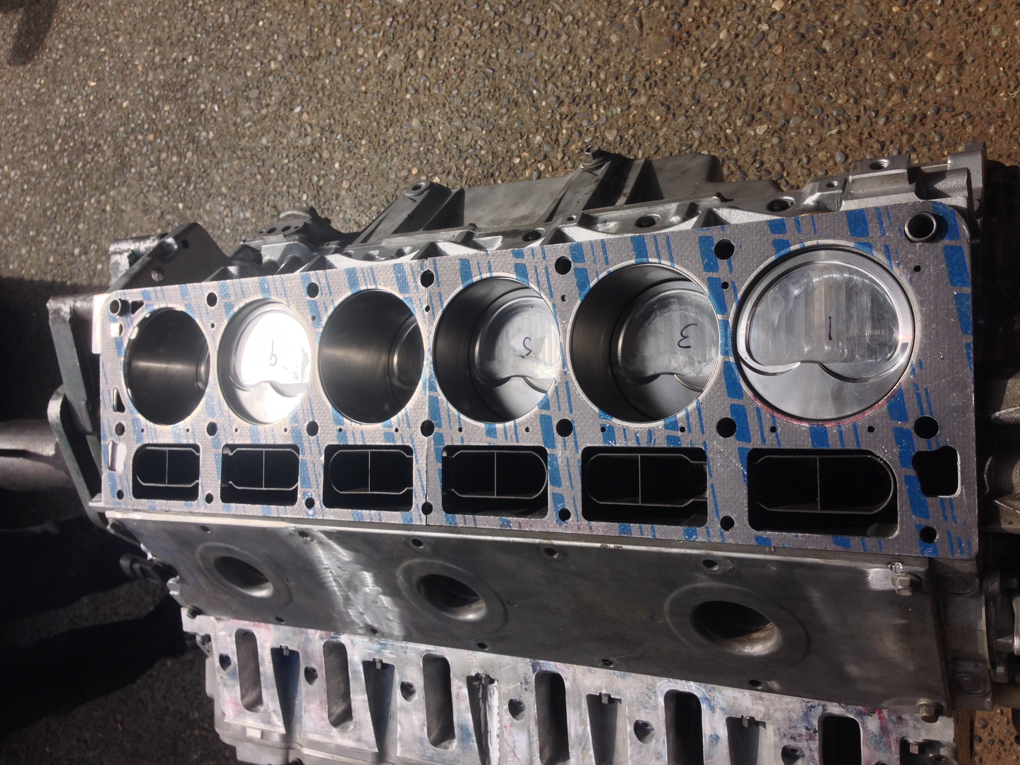
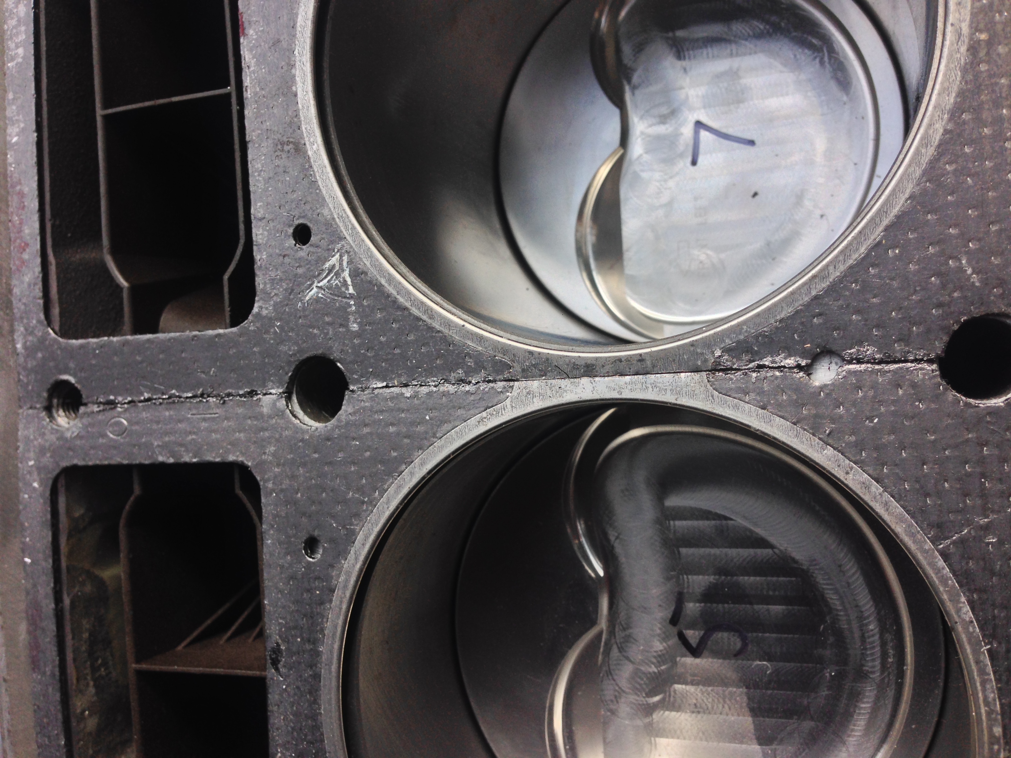
If you look at the stock headgasket, it'll be a little easier to see. The amount of water that actually flows through the deck is very minuscule. The water's main path is down the block, up through the head, and back the other way. There are small holes in the headgasket that allow for steam to escape. We considered replicating the original shape in, but it would essentially be cosmetic at that point and we'd much rather keep that area where the weld is as strong as possible. We're planning on drilling holes to match the headgaskets, but other than that, it seems really unnecessary to us. Thank you for the question!
Due to the custom nature of the job, we're not exactly sure. Ideally we'd have it running next weekend, but there's more to do. Fab work to the intake manifold, and then its onto the Fuel/Spark systems. I'll be much better at updating the progress as we go, however!
03-26-2015, 10:48 PM
#589
Staging Lane
Thread Starter
Join Date: Apr 2013
Location: Seattle, Washington
Posts: 53
Likes: 0
Received 0 Likes
on
0 Posts
We ended up splicing two together. We don't think it will be an issue, but if it is we'll have to do some more searching and find somebody to custom make some. I can post a picture of them on the head if that's something that interests people!
 03-27-2015, 08:54 PM
#591
Staging Lane
Thread Starter
Join Date: Apr 2013
Location: Seattle, Washington
Posts: 53
Likes: 0
Received 0 Likes
on
0 Posts
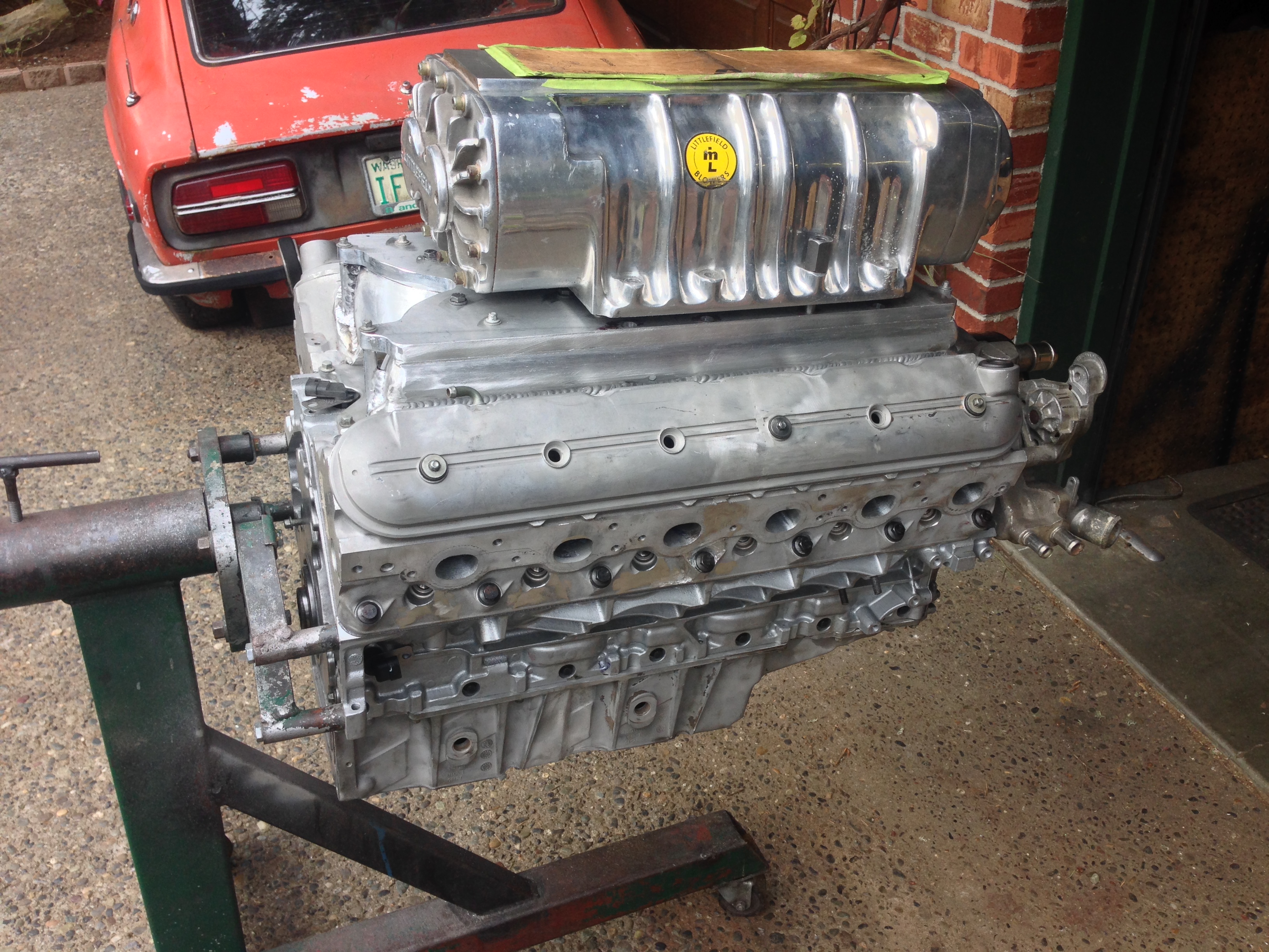
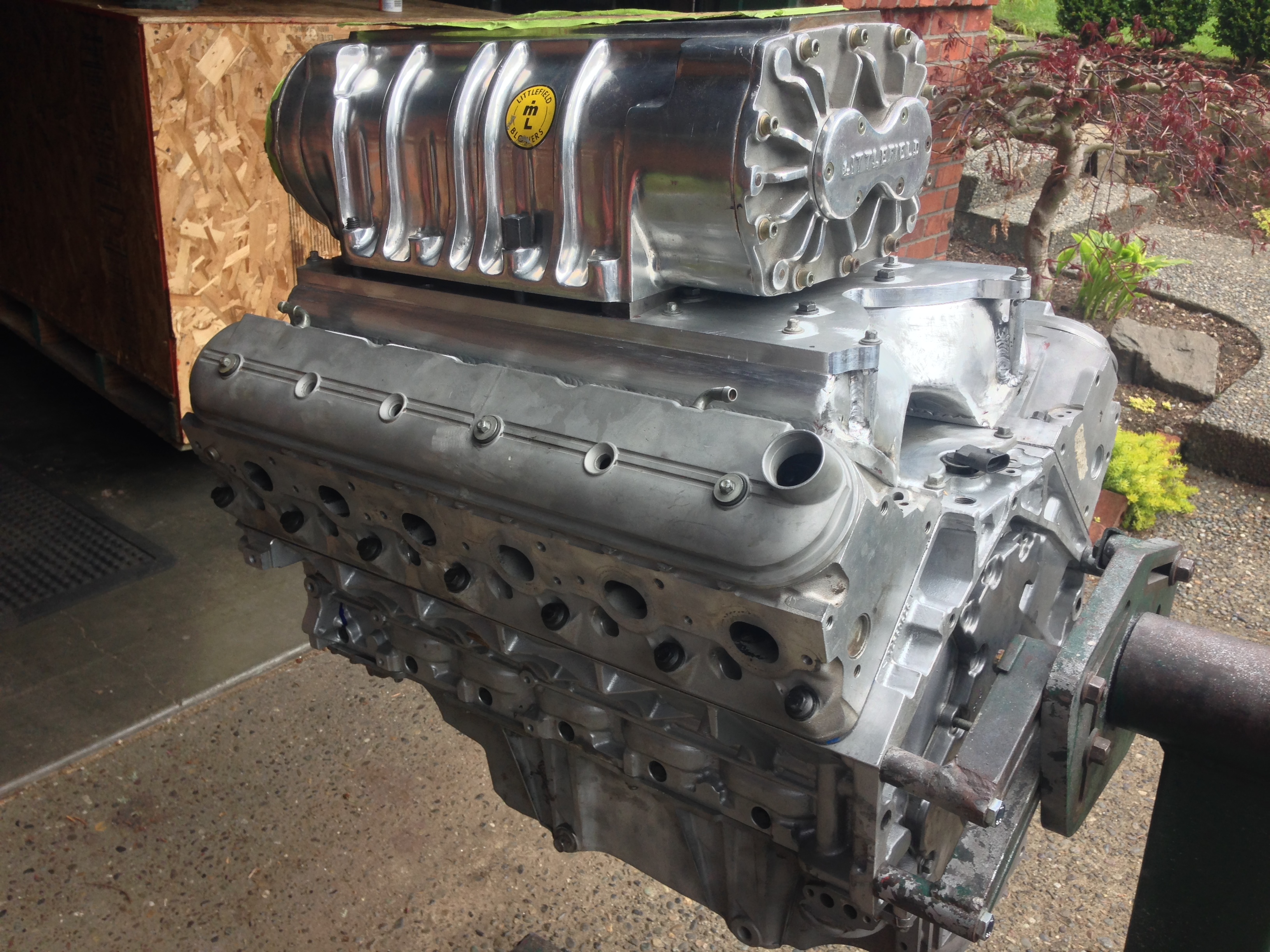
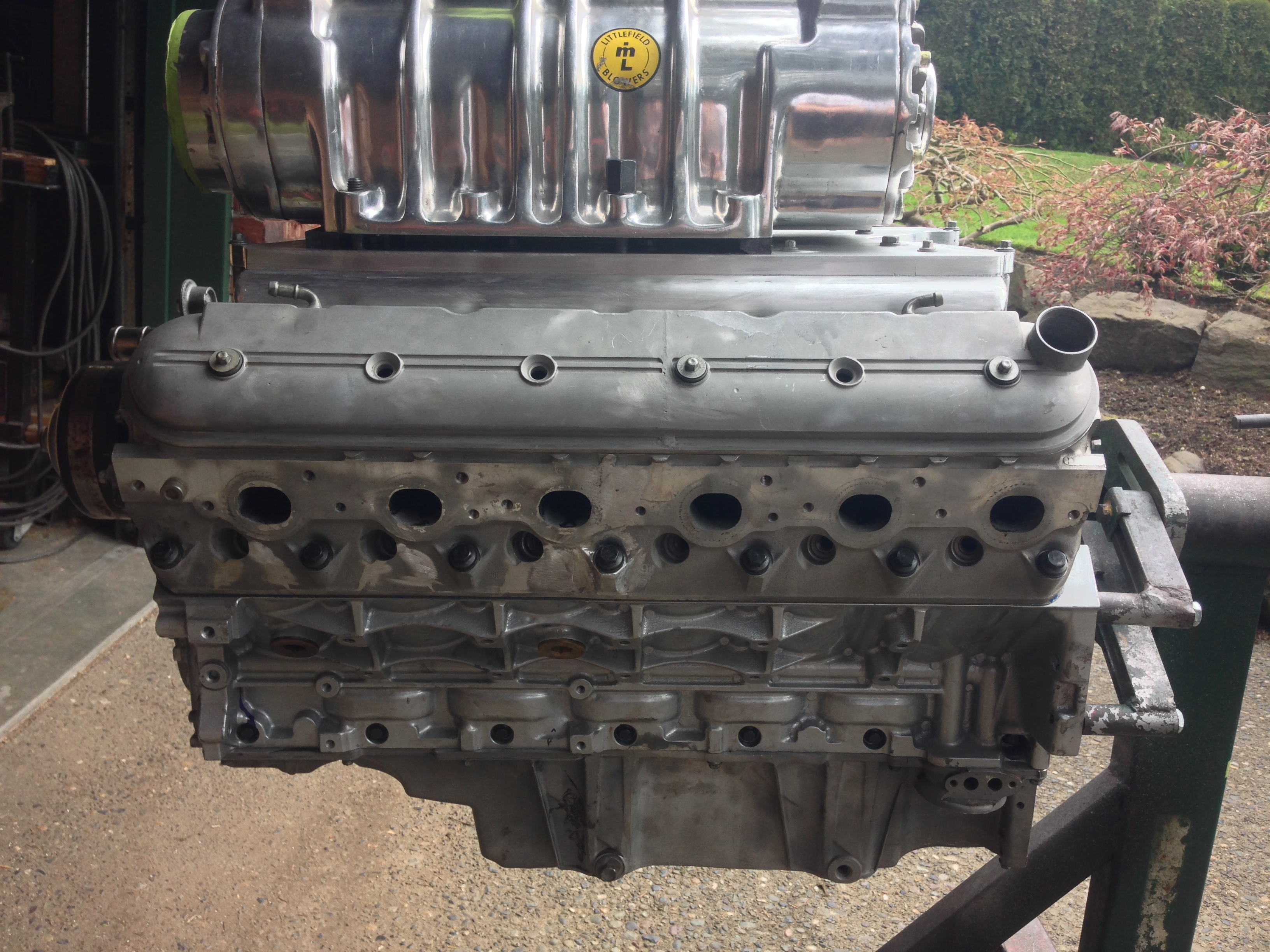
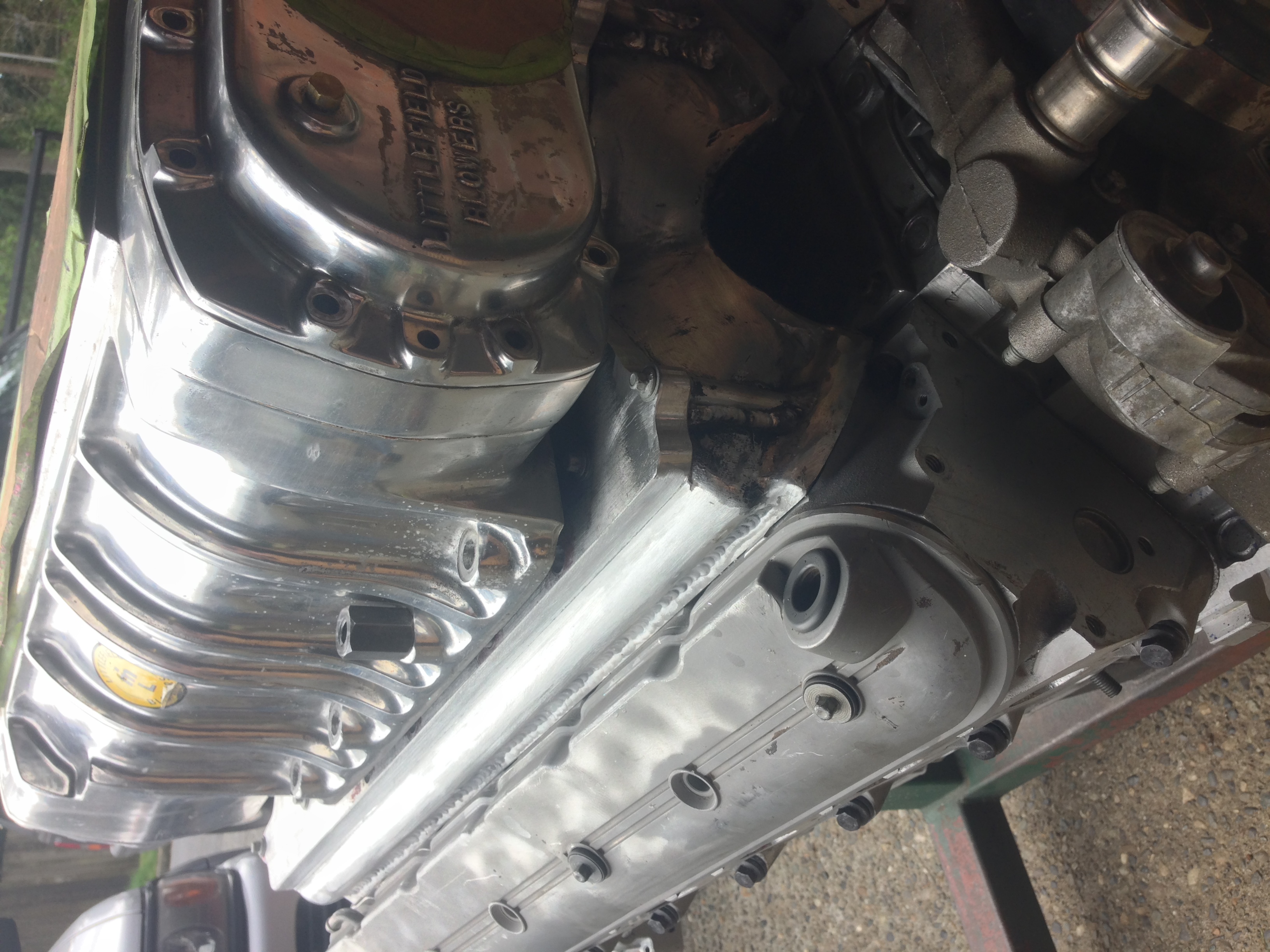
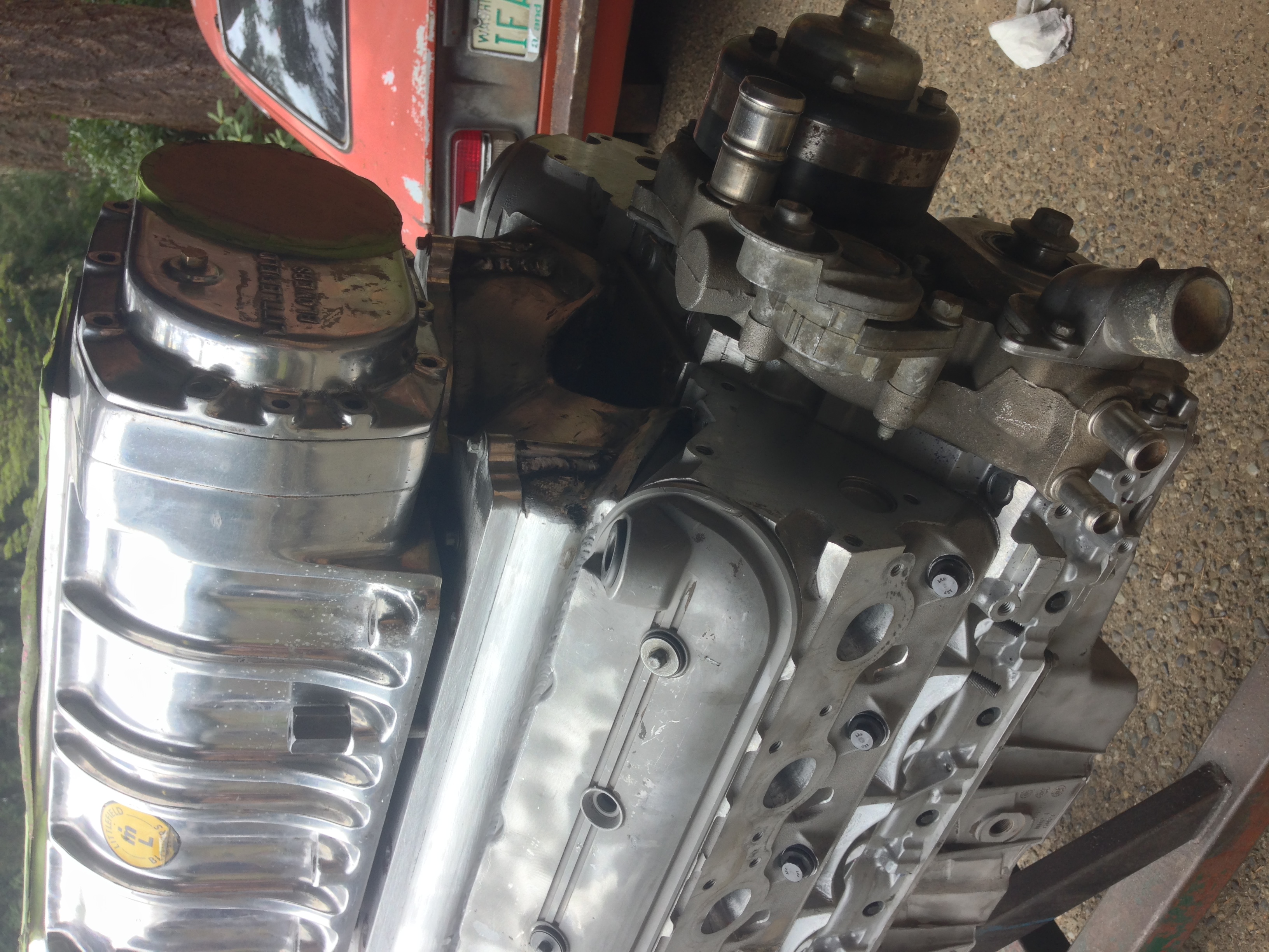
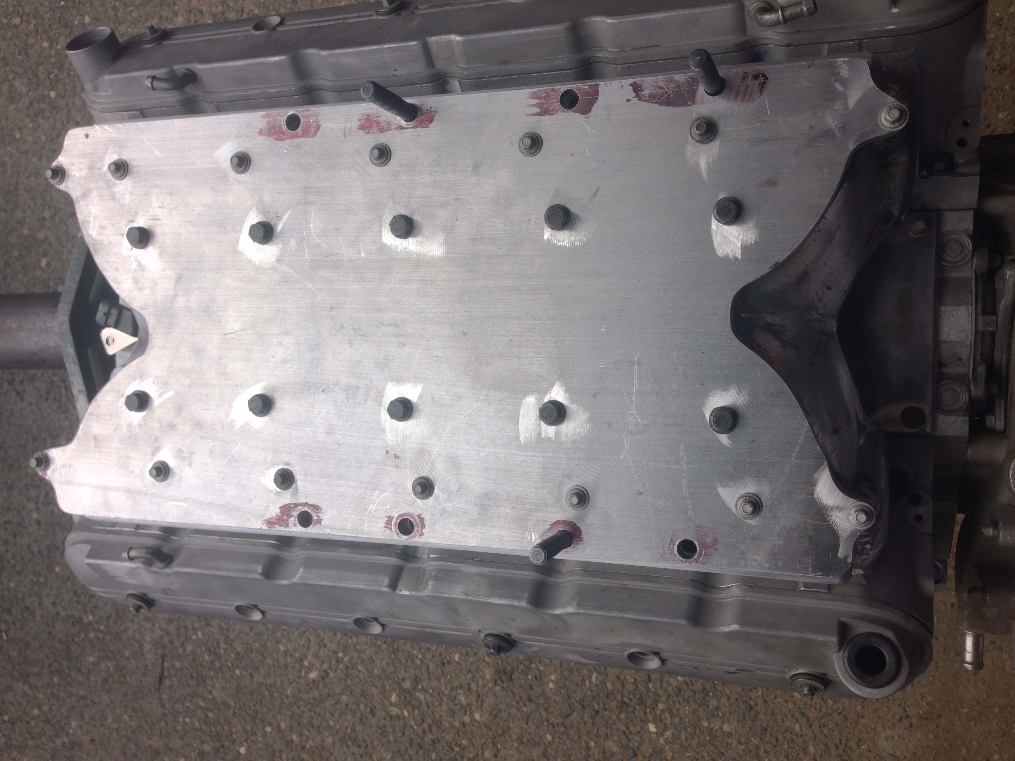
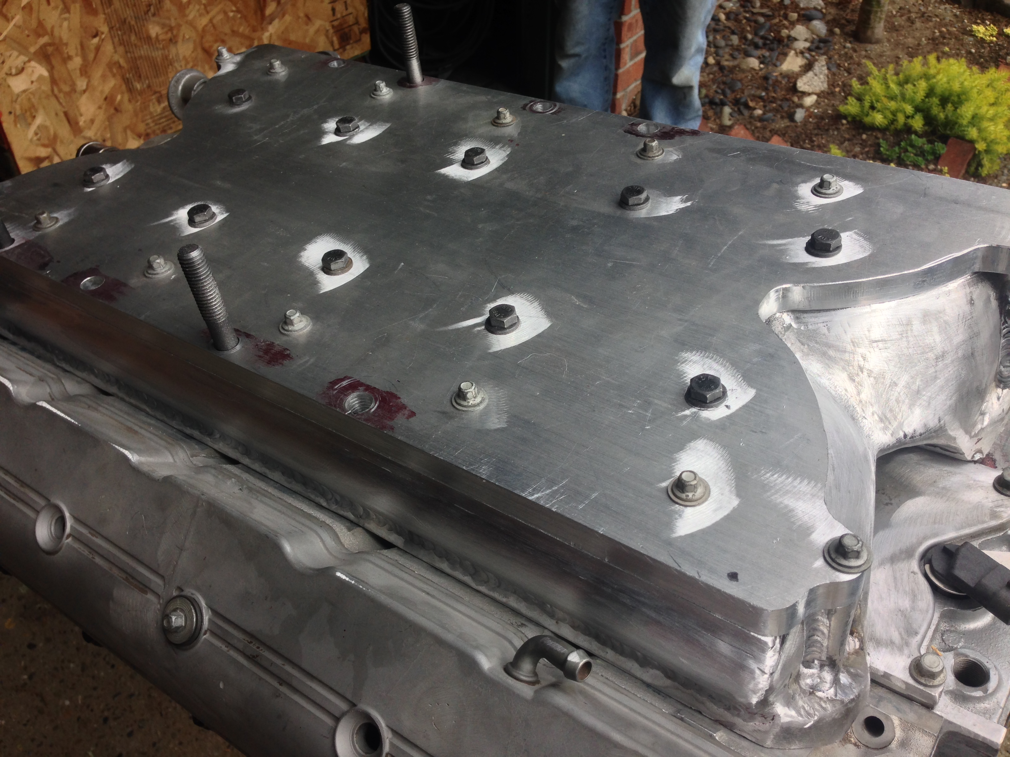
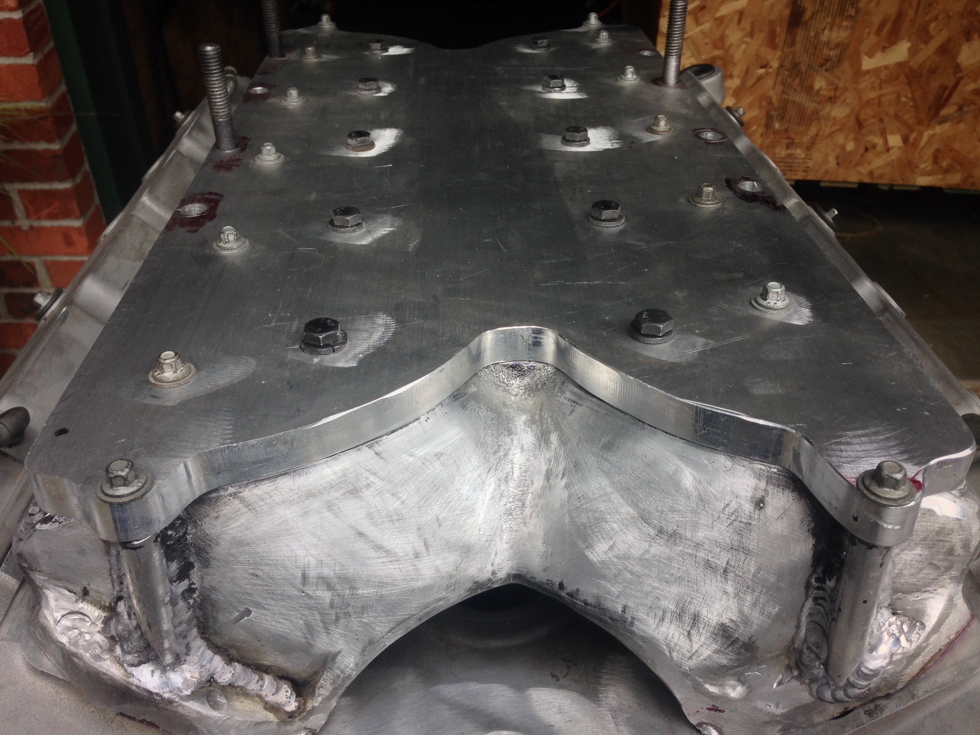
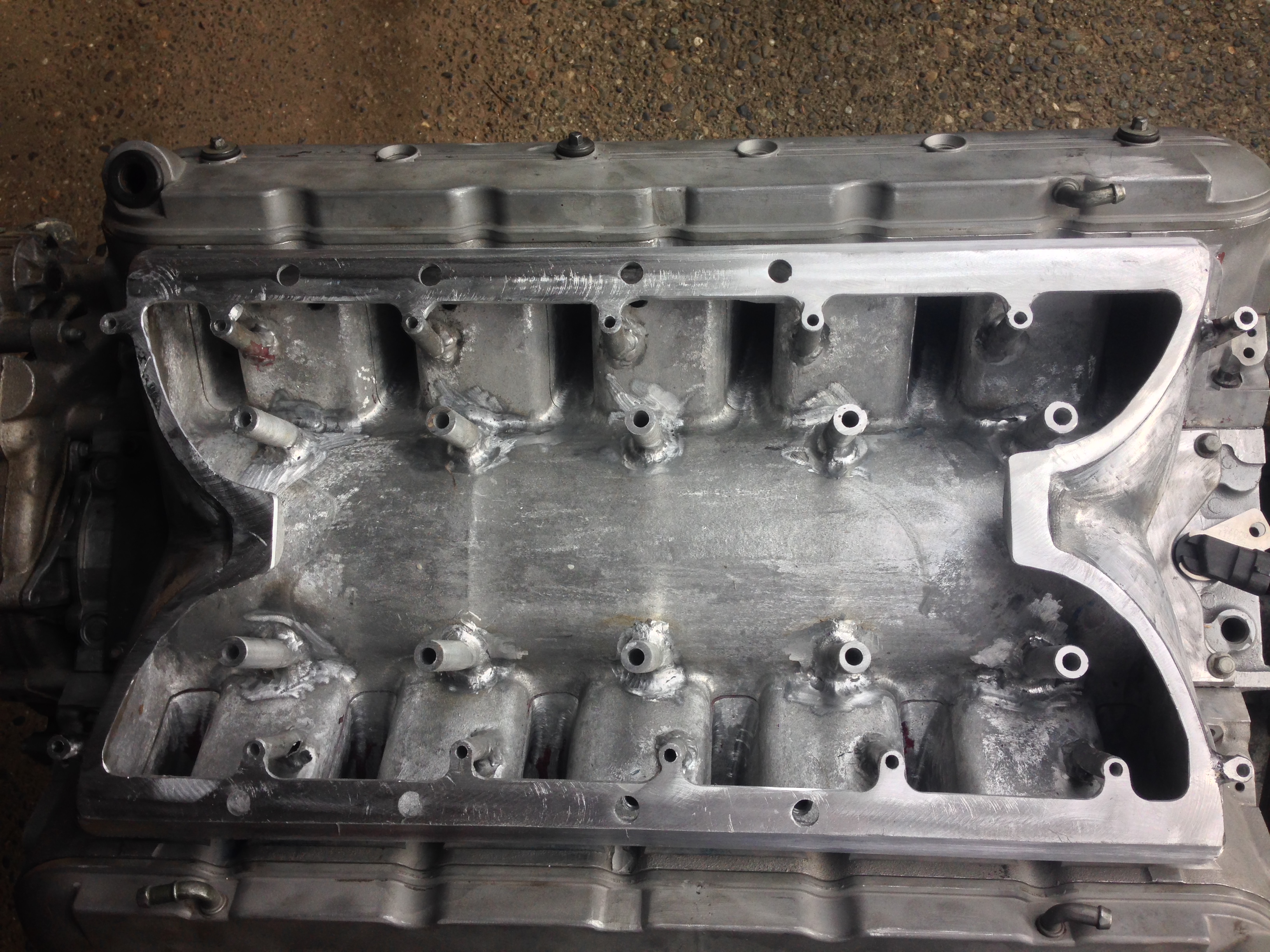
The intake manifold is almost complete. We added extra bolts that ties the manifold to the block and to the heads. The bolts you see aren't the ones we're planning to use, we will counter sink them into the plate. We obviously still have to cut the hole for the blower.
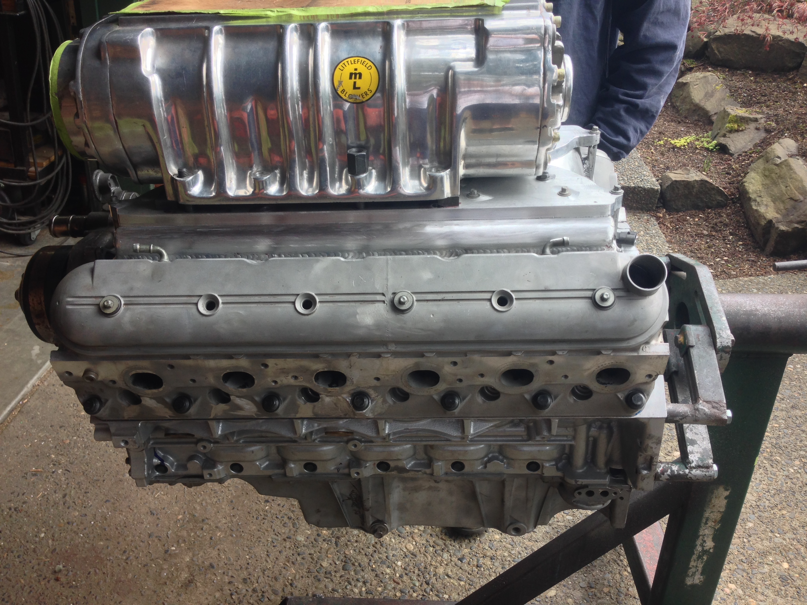
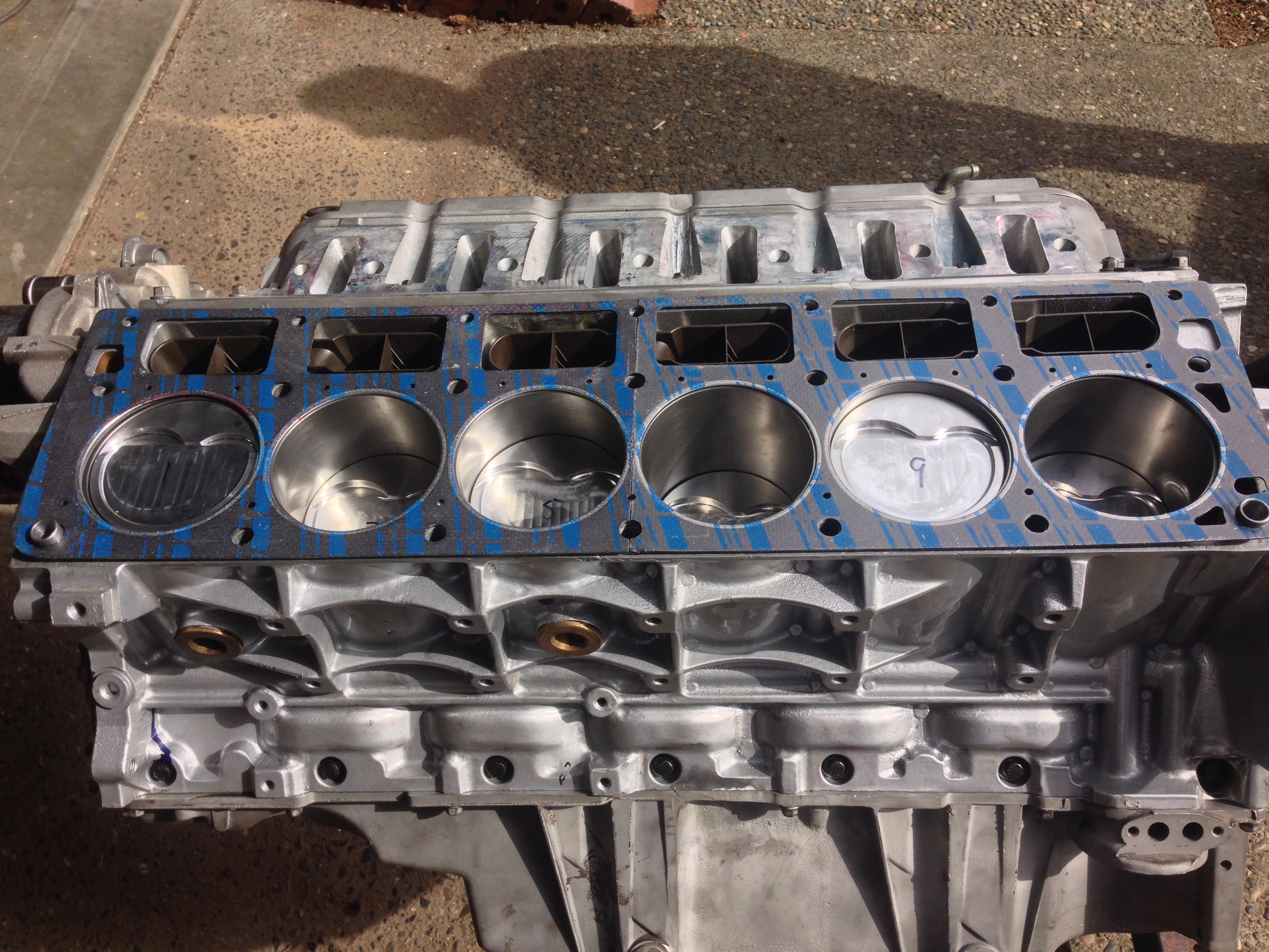
The headgaskets were cut in the middle, as shown in the pictures. They are exactly what we were looking for, size wise, after the cut. We kept all the fur on the edges, which should help mesh them together when torqued up. When cutting, we used a table saw and put the stainless ring on the top so no tears occurred.
We're considering looking for a good crankshaft builder. If that interests you, feel free to message me and we can talk. The crankshaft balances like a regular v8, so nothing to be afraid of. Thanks!
 04-03-2015, 03:37 PM
#595
Staging Lane
Thread Starter
Join Date: Apr 2013
Location: Seattle, Washington
Posts: 53
Likes: 0
Received 0 Likes
on
0 Posts
04-08-2015, 10:10 AM
#596
Staging Lane
Join Date: Jun 2006
Location: Medford, OR
Posts: 93
Likes: 0
Received 0 Likes
on
0 Posts
04-22-2015, 07:29 PM
#599
On The Tree

Join Date: Jan 2008
Location: Where you least expect me
Posts: 100
Likes: 0
Received 0 Likes
on
0 Posts
If you look at the stock headgasket, it'll be a little easier to see. The amount of water that actually flows through the deck is very minuscule. The water's main path is down the block, up through the head, and back the other way. There are small holes in the headgasket that allow for steam to escape. We considered replicating the original shape in, but it would essentially be cosmetic at that point and we'd much rather keep that area where the weld is as strong as possible. We're planning on drilling holes to match the headgaskets, but other than that, it seems really unnecessary to us. Thank you for the question!
Be ready with an IR laser thermometer to watch head temp at each cylinder while on the dyno.
I predicT that you *WILL* have to revisit coolant circulation.
04-23-2015, 01:22 PM
#600
TECH Apprentice
iTrader: (1)
Join Date: Mar 2009
Location: LA
Posts: 356
Likes: 0
Received 0 Likes
on
0 Posts
On the first page it says this isn't their first v12 build, just the first that they are keeping, and one is in a plane (brave ****** who flies that, if its flown) so I'm sure it cools fine, unless they're all having cooling issues