


Stepped exhaust vs smooth transition??
I didnt have much luck on the web or here searching for an answer and hopefully this is the right section.
Basically i am trying to figure out if there is much of a difference between a stepped exhaust coparedto a smooth transition. Both scenarios going from a 3" header to mid pipe , to a 3 1/2"mid pipe , to a 4"tailpipe.
Ive seen allotta articles on this for scavenging and increasing effeciency but would stepped transitions work as well or close to a smoth transition?
Thanks for any info or help on this matter.
Teching In
Joined: May 2010
Posts: 28
Likes: 0
From: Southeast USA
Maybe for some element of anti-reversion yes. I know power gains have been realized from having a small step from an exhaust port to header for the same reasons, but we're not talking 1/4" lip. Seems something that large would impart a lot of turbulence. I guess ultimately it'd have to be tested.
TECH Fanatic
Joined: Jun 2002
Posts: 1,979
Likes: 3
From: Upstate NY
I didnt have much luck on the web or here searching for an answer and hopefully this is the right section.
Basically i am trying to figure out if there is much of a difference between a stepped exhaust coparedto a smooth transition. Both scenarios going from a 3" header to mid pipe , to a 3 1/2"mid pipe , to a 4"tailpipe.
Ive seen allotta articles on this for scavenging and increasing effeciency but would stepped transitions work as well or close to a smoth transition?
Thanks for any info or help on this matter.
Now, why do you want to keep increasing the size of the tail pipe(s)? The exhaust is cooling drastically as it moves away from the engine. Cooler gas occupies less volume so it slows down even if the pipe size remains the same. As a gas slows down it's pressure increases....oops, just what you don't want in the tailpipe.
So keep the pipe size constant after the collector or muffler or even decrease the size. If you change size, do it smoothly with a tapered transition piece.
A 5 inch cofffee can on the end of a ricer's 1-3/4 inch tailpipe doesn't help power. Perhaps it hurts. Good chance.
Jon
On The Tree
Joined: Nov 2005
Posts: 184
Likes: 0
"Now, why do you want to keep increasing the size of the tail pipe(s)? The exhaust is cooling drastically as it moves away from the engine. Cooler gas occupies less volume so it slows down even if the pipe size remains the same. As a gas slows down it's pressure increases....oops, just what you don't want in the tailpipe"
Ok so does this theory conflict with the thinking behind steps in primary piping? The expansion and pressure increase is combatted with an increase in primary pipe sizing away from the exh.port. Do i have that right?
Ok so does this theory conflict with the thinking behind steps in primary piping? The expansion and pressure increase is combatted with an increase in primary pipe sizing away from the exh.port. Do i have that right?
Well see thats got me scratching my head.. I had a car craft mag a long time ago that did this on a 5.0 fox body mustang. They had a back to dyno comparison of a regular 2 1/2" H pipe or x pipe compared to a custom one with multiple steps starting with 2" to 2 1/4" to 2 1/2" and made it to a 3" tailpipe. They showed great results..but this was with a 302..which from what ive researched has poor flowing factory exhaust ports .
And this is the only article ive come across comparing a setup like that.
And in theory, in my head anyways, wouldnt all that hot expanded exhaust start a major scavenging affect as it not only cools and contracts but is pushed into a bigger area. Im just thinking of a reverse velocity stack if that makes any since.
TECH Fanatic
Joined: Jun 2002
Posts: 1,979
Likes: 3
From: Upstate NY
Well see thats got me scratching my head.. I had a car craft mag a long time ago that did this on a 5.0 fox body mustang. They had a back to dyno comparison of a regular 2 1/2" H pipe or x pipe compared to a custom one with multiple steps starting with 2" to 2 1/4" to 2 1/2" and made it to a 3" tailpipe. They showed great results..but this was with a 302..which from what ive researched has poor flowing factory exhaust ports .
And this is the only article ive come across comparing a setup like that.
And in theory, in my head anyways, wouldnt all that hot expanded exhaust start a major scavenging affect as it not only cools and contracts but is pushed into a bigger area. Im just thinking of a reverse velocity stack if that makes any since.
And this is the only article ive come across comparing a setup like that.
And in theory, in my head anyways, wouldnt all that hot expanded exhaust start a major scavenging affect as it not only cools and contracts but is pushed into a bigger area. Im just thinking of a reverse velocity stack if that makes any since.
It's hard to argue with Car Craft tech...

Megaphone exhausts do have some uses, but generally not on collected systems.
Velocity stacks' major contribution is to smooth intake airflow and not restrict it. The radius at the lip of the entrance is the important part, IMO.
Originally Posted by LSwondeful
Ok so does this theory conflict with the thinking behind steps in primary piping? The expansion and pressure increase is combatted with an increase in primary pipe sizing away from the exh.port. Do i have that right?
Collector length is still more important than 1) primary length, 2) primary steps and even 3) primary size.
Very often the biggest restriction in the exhaust system is the muffler. The good ones are basically invisible to the flow. The bad ones can defeat most of your efforts for good flow prior to the muffler. I always thought that those mufflers should be shaped like a potato and painted brown.
Jon
Old SStroker is correct; the steps or change in diameter causes a high energy reversion wave that comes back to the exhaust port. If the distance from the step to the valve is correct then the high energy wave will bounce off the valve right before it opens. Once it opens the high energy wave will help pull the exhaust out of the cylinder (one form of scavenging). If the step is too far from the valve it will hit the valve right as it is opening or right after it opened, causing the exhaust gas to be pushed back into the cylinder (which is overcome by the piston pushing it out). This will make you lose power.
So considering single pipes, the distance from the exhaust valve to the change in diameter (step/collector) is the most important factor.
There is another type of scavenging though, inertial scavenging. This comes into play with a single pipe, but more so with several pipes merging together (i.e manifold/header). This is where the pulse (mass of exhaust gas) from one cylinder is timed correctly to pass the merge point when another cylinder's exhaust valve is opening. This mass creates a vacuum behind it which helps to pull the other cylinders exhaust gas out of the cylinder.
With a properly setup exhaust system (tons of R&D) you can actually create the effect of a supercharger or turbo (to a much smaller degree). With the proper valve overlap you can actually get so much intake velocity caused by scavenging that the cylinder get more air/fuel mixture than barometric pressure would have pushed in there naturally; perhaps 15psia at sea level. This would only be 0.3 psig but is better than nothing! Race teams have seen much higher pressures, 2-3 psig or higher.
This did not really answer your question but might give you a better understanding of the variables involved with exhaust manifold design.
I had to type this quickly so forgive me some grammatical errors.
I am not an exhaust expert so if you disagree with anything I said or have anything to add please post up.
Nick
Trending Topics
That does clarify some grey area that i was foggy on. Is there any easy way to figure out when the pulse after the collector will hit the valve before opening , thus determining the required placement of a step after the collector?
And any reason why this could not be multiplied by numerous steps there after?
Thanks to everybodies insight on this.
And any reason why this could not be multiplied by numerous steps there after?
Thanks to everybodies insight on this.
LS1 Tech Stories
The Best V8 Stories One Small Block at Time

6 Common C5 Corvette Failures and What's Involved In Repairing Them
Pouria Savadkouei
Retro Modern Bandit Pontiac Trans AM Comes With Burt Reynolds' Autograph
Verdad Gallardo
Top 10 Greatest Cadillac V Series Performance Models Ever, Ranked
Pouria Savadkouei
Top 10 Most Powerful Chevy Trucks Ever Made!

Hennessey's New Supercharged Silverado ZR2 Has 700 HP
Verdad Gallardo
Coachbuilt N2A Anteros Is an LS2-Powered C6 Corvette In Italian Clothes
Verdad Gallardo
Awesome K5 Blazer Restomod Comes With C7 Corvette Power
Verdad Gallardo
10 Camaros You Should Never Buy

10 LS Engine Myths That Refuse to Die
Verdad Gallardo


That does clarify some grey area that i was foggy on. Is there any easy way to figure out when the pulse after the collector will hit the valve before opening , thus determining the required placement of a step after the collector?
And any reason why this could not be multiplied by numerous steps there after? Thanks to everybodies insight on this.
And any reason why this could not be multiplied by numerous steps there after? Thanks to everybodies insight on this.


Joined: Aug 2007
Posts: 24,241
Likes: 89
From: Turnin' Wrenches Infractions: 005
Dont know how relevant this is to the OP, but my car had Hedman Tork-Step headers on it when I bought it. They were 1 1/2 primaries stepped to 1 3/4 I believe. I swapped them for a set of straight 1 3/4 with no step and there was a huge loss of mid-range power. Power on the top-end picked up though. I assume the further down the exhaust you go the less relevant this gets.
Sorry to revive a dead thread, but I do have a little to contribute to anyone with questions on a stepped exhaust.
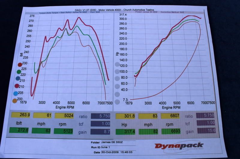
This is Motordyne. They make Nissan VQ35/VQ37 parts. The owner, Tony, is quite literally a rocket scientist. He applies his rocket science background to making car parts (and I've been trying to get him to make LSX parts) like this test pipe for a 350Z that uses a Helmholtz resonator to increase torque and eliminate rasp.

Does it work? Hell yes it does, I've installed a pair of these myself. Take at a look at the gains Motordyne Test Pipes with Helmholtz resonators made over generic test pipes. That's a 23ft-lb gain at 2300rpm on an independent back to back dyno test.

This is his exhaust for a 370Z. Tony spends most of his time doing R&D. By that I mean things like calculating the optimum distance from the collectors for an X-merge or designing and testing helmholtz resonators to remove drone. Aaaand that brings us to his exhaust which is stepped 2.5" to 3" using diffusers to transition. He literally spends months of R&D before releasing his exhausts but the independent dynos don't lie.

Here is his exhaust and test pipes vs against an HKS exhaust with high flow cats.
Further reading on his exhaust R&D:
http://my350z.com/forum/intake-exhau...k-for-n-a.html
This is Motordyne. They make Nissan VQ35/VQ37 parts. The owner, Tony, is quite literally a rocket scientist. He applies his rocket science background to making car parts (and I've been trying to get him to make LSX parts) like this test pipe for a 350Z that uses a Helmholtz resonator to increase torque and eliminate rasp.
Does it work? Hell yes it does, I've installed a pair of these myself. Take at a look at the gains Motordyne Test Pipes with Helmholtz resonators made over generic test pipes. That's a 23ft-lb gain at 2300rpm on an independent back to back dyno test.
This is his exhaust for a 370Z. Tony spends most of his time doing R&D. By that I mean things like calculating the optimum distance from the collectors for an X-merge or designing and testing helmholtz resonators to remove drone. Aaaand that brings us to his exhaust which is stepped 2.5" to 3" using diffusers to transition. He literally spends months of R&D before releasing his exhausts but the independent dynos don't lie.
Here is his exhaust and test pipes vs against an HKS exhaust with high flow cats.
Further reading on his exhaust R&D:
http://my350z.com/forum/intake-exhau...k-for-n-a.html
TECH Addict
Joined: Sep 2009
Posts: 2,481
Likes: 5
From: PA/MD
I don't know how I missed your update last year lol that is an odd looking setup, but looks like it works great. It reminds me of the chambers you see hanging off of intake tubes to make them quieter


I know this is old, but since it was bumped up I have a question.
So my question is, if you change the cam specs would the ideal placement of the step in a header change due to the valves opening at a different time?
I am currently running a set of the Edelbrock 1-3/4" to 1-7/8" stepped headers with 3.5" collectors that seem to make good power.
Old SStroker is correct; the steps or change in diameter causes a high energy reversion wave that comes back to the exhaust port. If the distance from the step to the valve is correct then the high energy wave will bounce off the valve right before it opens. Once it opens the high energy wave will help pull the exhaust out of the cylinder (one form of scavenging). If the step is too far from the valve it will hit the valve right as it is opening or right after it opened, causing the exhaust gas to be pushed back into the cylinder (which is overcome by the piston pushing it out). This will make you lose power.
So considering single pipes, the distance from the exhaust valve to the change in diameter (step/collector) is the most important factor.
So considering single pipes, the distance from the exhaust valve to the change in diameter (step/collector) is the most important factor.
I am currently running a set of the Edelbrock 1-3/4" to 1-7/8" stepped headers with 3.5" collectors that seem to make good power.

I wonder if this article will help answer the OP's question:
https://www.google.com/url?sa=t&rct=...45960087,d.eWU
https://www.google.com/url?sa=t&rct=...45960087,d.eWU