What to buy.. Projectors
 12-20-2007, 05:06 PM
#41
Copy & Paste Moderator

I haven't forgotten.
I was a way for a while and now that I'm back everything is covered in snow and I don't have a garage. This may have to wait for better weather.
I was a way for a while and now that I'm back everything is covered in snow and I don't have a garage. This may have to wait for better weather.
 12-20-2007, 07:43 PM
#42
On The Tree
Thread Starter
iTrader: (2)
Join Date: Jan 2007
Posts: 159
Likes: 0
Received 0 Likes
on
0 Posts
Well how do you think it turned out? Is the light distribution/ cutoff better? I've read I can use a piece of a pop can glued on with high heat silicon and painted with high heat paint, and that's what I was planning on doing to change my cutoff.
12-20-2007, 08:40 PM
#43
Copy & Paste Moderator
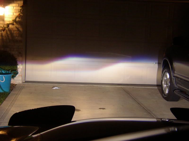
I do like the new square-stepped cut-off better. Its not as sharp as the old cut-off but its not that much different. There is a little more blue at the edge too (which some people strive for, but I'm looking for a decently sharp cut-off). I was able to drive with it yesterday and today. It is an improvement. I'll have to take pics to show you. I don't know where/when though. It looks kinda funny too with the driver-side square-stepped and the passenger-side the original slant (I'm going to change that one too when I'm able to).
I think I've read the same thread you read about using a pop can and high heat silicon.
I think I've read the same thread you read about using a pop can and high heat silicon.
12-22-2007, 06:23 PM
#44
Copy & Paste Moderator
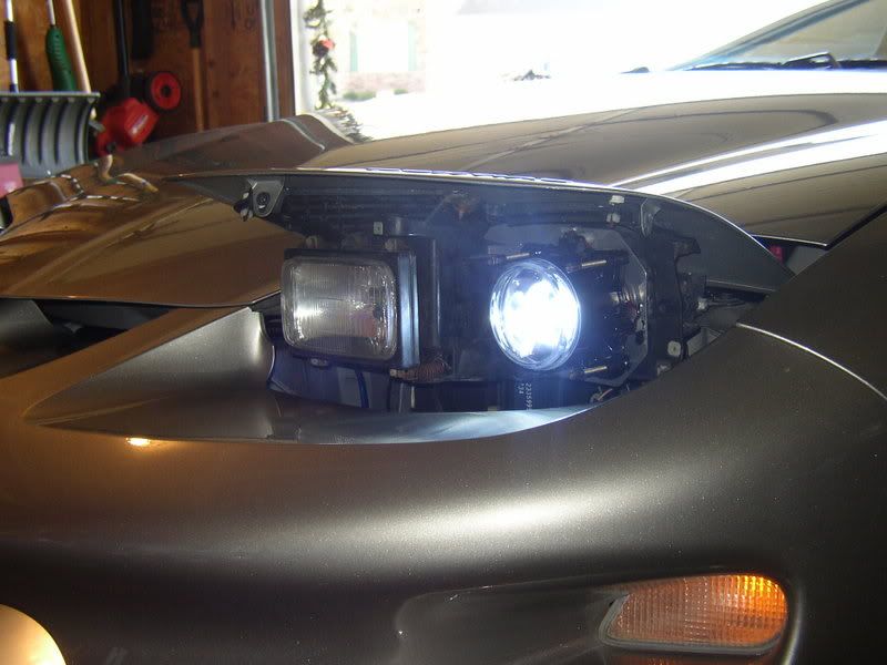
My brother and I modified the passenger-side cut-off today.
It still needs adjustment though.
The driver-side is square-stepped and the passenger side is straight.
Here is a preview.
No Lights, for reference:
(The white stuff on the ground is snow )
)
http://www.fadingarrow.com/images/Ne...1_NoLights.jpg
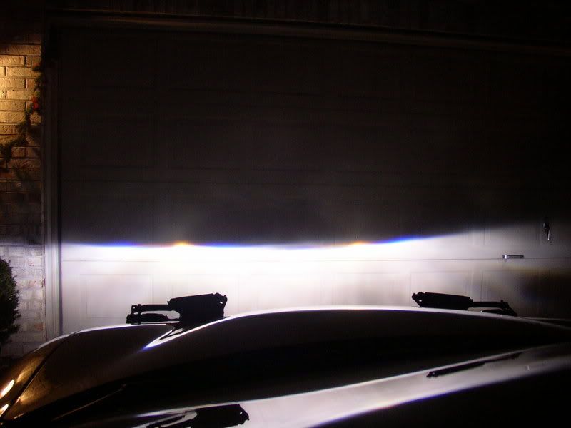
Low Beam Only:
http://www.fadingarrow.com/images/Ne...wBea0mOnly.jpg
The passenger-side can be made sharper (I could have sworn I had it sharper than that before I installed it on the car). I'll have to disassemble it again to adjust. I did test before closing it up, but I guess it moved before I tightened it all down or maybe I hit it. Oh well. Maybe I'll tackle it tomorrow.
BTW, the black bit on the wall appears to be a scorch mark.
It still needs adjustment though.
The driver-side is square-stepped and the passenger side is straight.
Here is a preview.
No Lights, for reference:
(The white stuff on the ground is snow
)http://www.fadingarrow.com/images/Ne...1_NoLights.jpg
Low Beam Only:
http://www.fadingarrow.com/images/Ne...wBea0mOnly.jpg
The passenger-side can be made sharper (I could have sworn I had it sharper than that before I installed it on the car). I'll have to disassemble it again to adjust.
I did test before closing it up, but I guess it moved before I tightened it all down or maybe I hit it. Oh well. Maybe I'll tackle it tomorrow.BTW, the black bit on the wall appears to be a scorch mark.
Last edited by VIP1; 12-22-2007 at 06:29 PM.
12-24-2007, 12:40 PM
#46
Copy & Paste Moderator
Even before I modified it, the driver-side wasn't much sharper than that. The passenger side was always sharper. I think its the lens. The driver-side is done. The orange flare in the middle of the the passenger-side can be removed though. I thought I had removed that flare. I'll have to open it up again and adjust it.
 12-25-2007, 12:46 AM
#53
Copy & Paste Moderator
If they are that cheap then they probably aren't that great.
Any pics? Links?
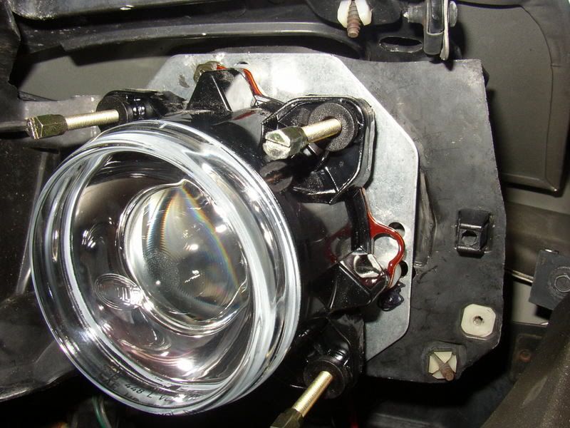
For mine, my brother and I made new cut-off shields out of aluminum. We traced out the old one for reference and drew on the new line we wanted. Then used tin snips to get the general shape and files to get it down to the exact shape we wanted. Then we drilled mounting holes in the new shields and mounted them in the original location using the original hardware. After the new cut-off shield and lens were mounted in the projector body, I mounted the bulb in the projector and used a spare connector and pigtail connected to a a jump-pack for power to see the pattern on the wall. I slowly pushed on the new shield to bend it and get a crisper cut-off. The bending was trial-and-error seeing the pattern on the wall.
Any pics? Links?
For mine, my brother and I made new cut-off shields out of aluminum. We traced out the old one for reference and drew on the new line we wanted. Then used tin snips to get the general shape and files to get it down to the exact shape we wanted. Then we drilled mounting holes in the new shields and mounted them in the original location using the original hardware. After the new cut-off shield and lens were mounted in the projector body, I mounted the bulb in the projector and used a spare connector and pigtail connected to a a jump-pack for power to see the pattern on the wall. I slowly pushed on the new shield to bend it and get a crisper cut-off. The bending was trial-and-error seeing the pattern on the wall.
Last edited by VIP1; 12-25-2007 at 01:10 AM.
12-25-2007, 03:49 PM
#54
On The Tree
Thread Starter
iTrader: (2)
Join Date: Jan 2007
Posts: 159
Likes: 0
Received 0 Likes
on
0 Posts
Well, the projectors came in, and realized this is going to be more of a project than I was originally expecting.. I'm going to have to modify the bumper to fit the lights where I was wanting to mount them, and I will be mounting the lights behind the bumper, meaning the bumper needs to come off to mount them. Hopefully I won't have to take it off to replace a bulb if ever one goes out.
I think I'm going to jump in to HID, probably 6000K. I'm thinking that mounting them in the fog light area will actually yield better results than the headlights area, because the height difference is only about 6 inches, and because the fog light area is not so recessed, the light should project better down and to the sides.
I'll probably start the installation process when the HID kit comes in, so now I just have to decide on a kit.
12-25-2007, 07:32 PM
#55
Teching In

Join Date: Nov 2006
Posts: 48
Likes: 0
Received 0 Likes
on
0 Posts
I did something much simpler to modify mine than VIP.
Glue + Aluminum Foil
Glue aluminum foil over the angled part.
Like this:

Try this site for help:
http://bellsouthpwp.net/m/u/mulgeary/Hella90/
Glue + Aluminum Foil
Glue aluminum foil over the angled part.
Like this:
Try this site for help:
http://bellsouthpwp.net/m/u/mulgeary/Hella90/
12-25-2007, 08:06 PM
#56
Copy & Paste Moderator
That is the ECE shield.
Mine were DOT.
My brother and I made new shields instead of modifying the old ones because I wanted a new stepped cut-off and I wanted to be able to return to the old shields if it didn't turn out right.
My brother and I re-adjusted the passenger-side cut-off shield today. Its not perfect, but its better. At the same distance as the previous pic, there is still a bit of an orange flare, but as the distance increases, the line changes to a straiter purple line. I had difficulty in getting a line that would look good at short distance and further distance so I went with something that worked better for greater distance.
I didn't take any pics today, but I will soon.
In the end, I'm quite happy. Its not perfect, but its a dramatic improvement over stock.
 12-26-2007, 10:28 AM
#58
Copy & Paste Moderator
Originally Posted by TheGr8Schlotzky
After looking at the picture again and knowing how those projectors are assembled.... how did you take that picture from inside the projector?
Originally Posted by TheGr8Schlotzky
Basically I'm just adding a bit of material to the left side to make it more flat, correct?
Or you can make a new shield without that stepped down section so that you get a flat line at the height of the "high" side of the shield which is actually the low side of the beam output (the lens flips the light output). Or you can make it a shorter square-step like I did for the driver-side. Since you are using it in the fog light location, you should probably stick with a flat/straight line. That sounds confusing. Let me know if I'm not being clear.
Last edited by VIP1; 12-26-2007 at 10:40 AM.
12-26-2007, 04:01 PM
#59
On The Tree
Thread Starter
iTrader: (2)
Join Date: Jan 2007
Posts: 159
Likes: 0
Received 0 Likes
on
0 Posts
I took that picture through the bulb opening. You don't see the edge because i zoomed in a bit to get rid of that.
Alright, that makes more sense. I was observing my beam pattern by hooking up the light to my computers power source and I was thinking how much better a line the bottom part is compared to the upper part, and wondering why I would want to add material rather than taking off the step up.
I was actually thinking I may just modify the left light to make it entirely flat, and keep the right one as is for the step up, or I might just add less to that side to keep the step up, but lessen it. I'll probably start this up today.
12-26-2007, 05:35 PM
#60
Copy & Paste Moderator
Originally Posted by TheGr8Schlotzky
I took that picture through the bulb opening. You don't see the edge because i zoomed in a bit to get rid of that.
Originally Posted by TheGr8Schlotzky
I was observing my beam pattern by hooking up the light to my computers power source and I was thinking how much better a line the bottom part is compared to the upper part, and wondering why I would want to add material rather than taking off the step up.
Originally Posted by TheGr8Schlotzky
I was actually thinking I may just modify the left light to make it entirely flat, and keep the right one as is for the step up, or I might just add less to that side to keep the step up, but lessen it. I'll probably start this up today.