

2BFAST'S 69 Camaro 4L60E Build
 02-11-2021, 11:47 PM
#81
TECH Enthusiast
I'm late to the party here, but you can't go wrong listening to @MaroonMonsterLS1 , @vorteciroc, @Kfxguy and others advise on here. I'm a retired stock transbuilder and have focused on performance build's since 2011. They have helped me learn a-lot about the performance mod's, so I don't have to do very much rework from going to far. Looks like a very nice build project. Better to do it right once and over kill some. That way anything you may want to change on the motor, tour trans will be ready. Glad you decided to drop the 5 pinion planets idea. I have used all 3 styles of Mason Smith's drum's multiple times. He has a great products and great product support too.
Thanks for all the details and pictures, it will help someone else do the same.
Thanks for all the details and pictures, it will help someone else do the same.
 02-12-2021, 10:04 AM
#82

I'm late to the party here, but you can't go wrong listening to @MaroonMonsterLS1 , @vorteciroc, @Kfxguy and others advise on here. I'm a retired stock transbuilder and have focused on performance build's since 2011. They have helped me learn a-lot about the performance mod's, so I don't have to do very much rework from going to far. Looks like a very nice build project. Better to do it right once and over kill some. That way anything you may want to change on the motor, tour trans will be ready. Glad you decided to drop the 5 pinion planets idea. I have used all 3 styles of Mason Smith's drum's multiple times. He has a great products and great product support too.
Thanks for all the details and pictures, it will help someone else do the same.
Thanks for all the details and pictures, it will help someone else do the same.
Ironic you mention Mason from 4L79. I actually did have a slight issue with the drum I got that I stumbled across that I didnt post. I shot him an email about it with a few pictures and within an hour he responded and said to send it back to him and he will take care of it no problem at all. I sent it back and he got everything taken care of and had it shipped back out that same day. Pretty awesome if you ask me.
 02-12-2021, 11:49 AM
#83
Started to assemble the unit now that all the sub-assemblies are assembled and ready to go
Case bushing with slots pointed up. Set the bushing in about 1/8" below the lip
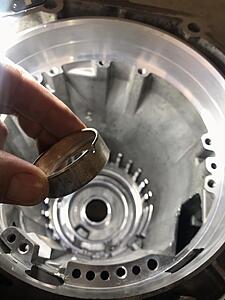
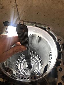
Used the factory output shaft to tap the bushing in. Dont hate, that shaft is plenty hard to tap the bushing in and not even phase it
I kinda got in a groove and got the low/rev piston, lower carrier hub, lower carrier, low/rev wave, then clutch stack, then low roller hub with Sonnax inner race. Then realized I didnt take any pics! But, nothing special just follow procedure. Just make sure the snap ring doesnt go over the anti-clunk spring!
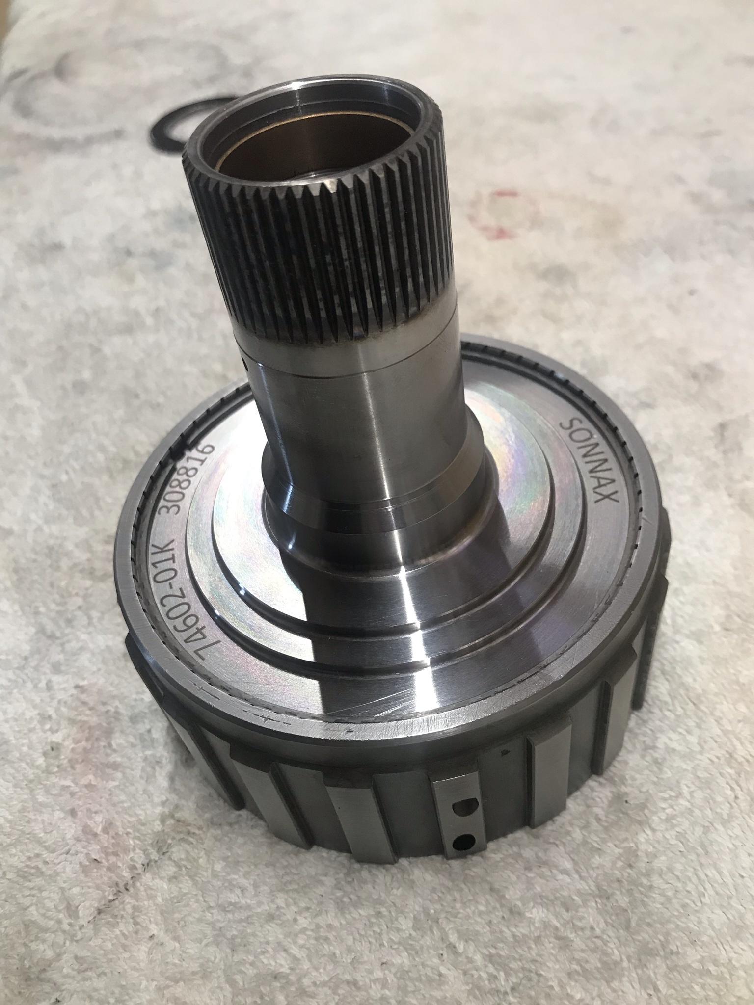
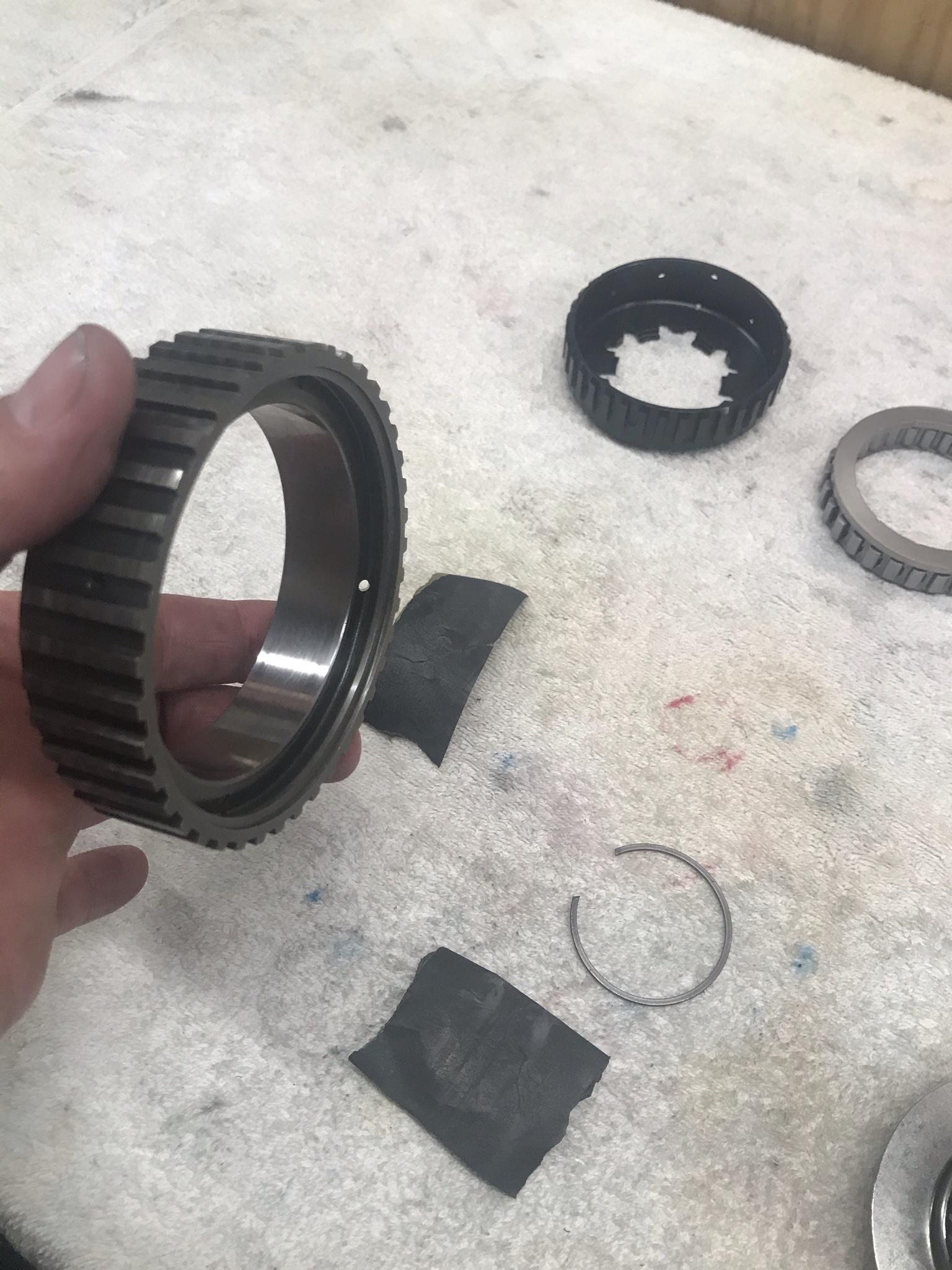
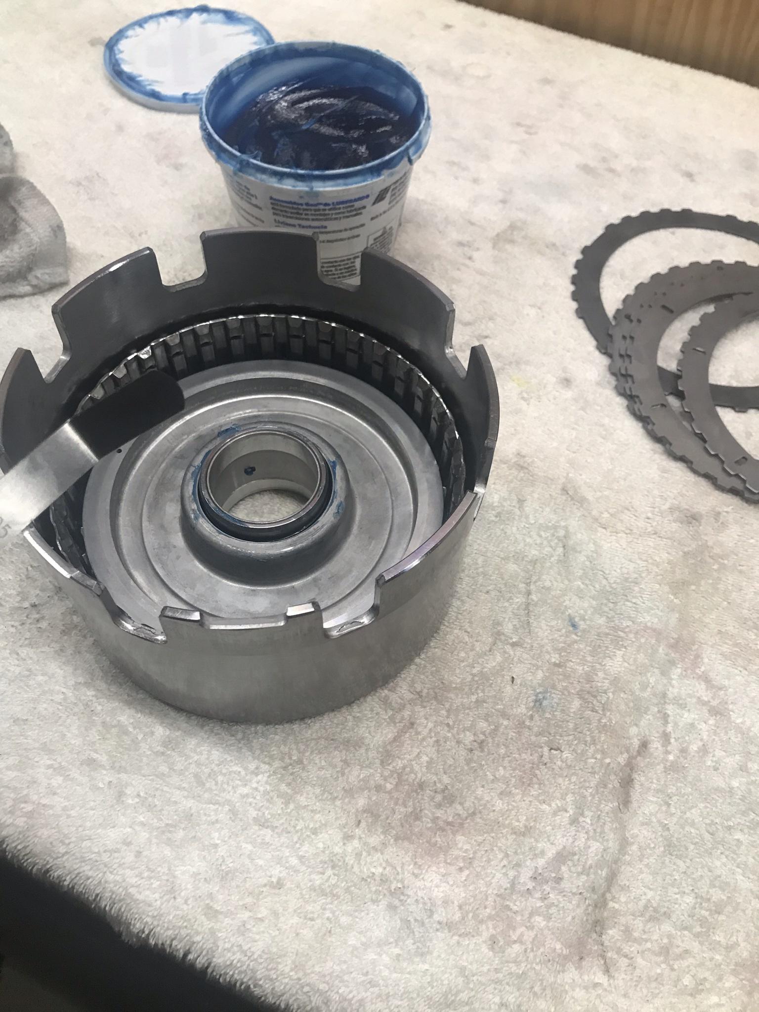
Few pics of the Sonnax Smart shell. Now that I have had this in my hands this is a REALLY nice piece the way the brace the collar and convert to roller bearing from a thrust washer. Also the ends of the shell where they couple with the reverse input drum are also heat treated.

Coupled with the Sonnax reaction tube.

Spins nice and free and smooth!

Case bushing with slots pointed up. Set the bushing in about 1/8" below the lip
Used the factory output shaft to tap the bushing in. Dont hate, that shaft is plenty hard to tap the bushing in and not even phase it

I kinda got in a groove and got the low/rev piston, lower carrier hub, lower carrier, low/rev wave, then clutch stack, then low roller hub with Sonnax inner race. Then realized I didnt take any pics! But, nothing special just follow procedure. Just make sure the snap ring doesnt go over the anti-clunk spring!

Few pics of the Sonnax Smart shell. Now that I have had this in my hands this is a REALLY nice piece the way the brace the collar and convert to roller bearing from a thrust washer. Also the ends of the shell where they couple with the reverse input drum are also heat treated.


Coupled with the Sonnax reaction tube.
Spins nice and free and smooth!
 02-13-2021, 04:54 AM
#84

Two things here. When setting the band clearance. DO NOT put any seals on the servos. You know you will have to grind the tip of the pin. When doing this, make sure you keep the tip round and polished. In the end you want minimum band clearance here. I started not roughing up the outer race, when I noticed that the new races from GM were no longer having the machined grooves in the outer race. And (it hit me all at once) that the TH400 intermediate outer race were always smooth. And they were having less problems with their sprag races that the 700R4/4L60E. Now I have been doing the same on the inner and outer race. I make the inner race flat and then polish with 1,000 then 1,500 then finally with 2,000 grit for a "mirror" finish. I have been doing this for about 3 years now. The smoother the surface, the more contact area the sprag has and the faster it will stop and with less wear. I gather GM knew this (no evidence though). Either way this is a learning process. And sometimes looking back on another transmission using the same type setup, will get you to thinking about what works and does not work...
The following users liked this post:
n2xlr8n66 (06-30-2021)
02-15-2021, 10:19 AM
#85
Two things here. When setting the band clearance. DO NOT put any seals on the servos. You know you will have to grind the tip of the pin. When doing this, make sure you keep the tip round and polished. In the end you want minimum band clearance here. I started not roughing up the outer race, when I noticed that the new races from GM were no longer having the machined grooves in the outer race. And (it hit me all at once) that the TH400 intermediate outer race were always smooth. And they were having less problems with their sprag races that the 700R4/4L60E. Now I have been doing the same on the inner and outer race. I make the inner race flat and then polish with 1,000 then 1,500 then finally with 2,000 grit for a "mirror" finish. I have been doing this for about 3 years now. The smoother the surface, the more contact area the sprag has and the faster it will stop and with less wear. I gather GM knew this (no evidence though). Either way this is a learning process. And sometimes looking back on another transmission using the same type setup, will get you to thinking about what works and does not work...
Also I do remember you talking about prepping the sprag races on the phone at one time. I took mine apart and did this. I initially used scotchbrite and cleaned the original witness marks off but then cleaned it up with 1000 then 2000. Polished up nice!

Input drum should be back here today. Got the pump together, lined up, and torqued down
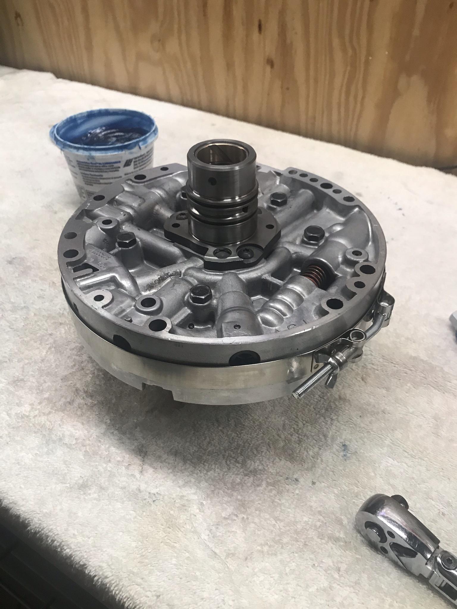
And the reverse input drum together
 02-15-2021, 11:52 AM
#86
TECH Junkie
There are two different style Torrington-Bearings, that are used between the front Planet and the front Hub/ Ring-Gear.
The Sonnax Hub will fit both styles of Torrington-Bearing...
You will have to match the front Planet to the correct style of Torrington-Bearing.
Double-check the instructions that were included with the Sonnax Hub for proper use/ matching components.
Most of the 4-Pinion front Planets will use the "Old Style" Torrington-Bearing without a "Lip".
The Sonnax Hub will use an included Shim with the Torrington-Bearing without a "Lip".
Here is a HyperLink to the Instructions
02-15-2021, 11:55 AM
#87
TECH Junkie
I also noticed that you went and snuck/ sneaked in the rear 5-Pinion Planet. 
The following users liked this post:
2BFAST (02-16-2021)
 02-15-2021, 08:45 PM
#89
TECH Junkie
2BFAST, What are you planning on using for Accumulator parts/ arrangement?
Are you using the Accumulator-Valve that came stock in your transmission core...
along with modifications from TransGo/ Dana ProBuilt Automatics?
When you are ready, please post which Accumulator Valve-Train that you are using... and which piston/ spring arrangements that you are using.
The "CX" Accumulator Valve-Train seems to be the most popular in performance builds.
There were originally 4 different Accumulator Valve-Train arrangements for the 4L60E transmission family:
-"A/ AX"
-"B/ BX"
-"C/ CX"
-"D/ DX"
These are NOT to be confused with ANY of the THM700-R4 Accumulator Valve-Train Letters (A, B, F, K, L, M, and N) as they do NOT share the same dimensions as the same parts used in the 4L60E transmission family.
Generally the "DX" Valve/ Sleeve is considered to be the firmest shifting Accumulator Valve-Train...
and the others are progressively softer shifting... with "AX" being the softest shifting.
Towards the end of the 4L60E production other Accumulator Valve-Train sizes were produced...
They are "R" and "YZ". I will not be discussing them here.
The Valve Land dimensions are as follows:
-AX: Torque-Signal Fluid =0.393" and Orificed-Accumulator Fluid =0.378"
-BX: Torque-Signal Fluid =0.393" and Orificed-Accumulator Fluid =0.359"
-CX: Torque-Signal Fluid =0.397" and Orificed-Accumulator Fluid =0.346"
-DX: Torque-Signal Fluid =0.401" and Orificed-Accumulator Fluid =0.327"
From these dimensions, the valve land size shows that a larger land for Torque-Signal Fluid will firm-up shifts...
however, a larger land for Orificed-Accumulator Fluid will soften-up shifts.
The circuits that pass through/ are regulated, and the circuits that act upon the Accumulator Valve-Train are not just as simple as the information provided thus far...
Spring force/ pressure and the location of the Spring relative to the Valve; play a major role in the behavior of the Valve-Train and corresponding circuits.
The fluid volume and pressure of these circuits... as well as their orifices also play a major role in said behavior.
I have had a large number of private messages here recently... regarding Accumulation.
So here was some information pertaining to the 4L60E transmission family... I will be starting a more involved thread on this information soon.
This has been a relatively simple explanation of the Accumulator Valve-Train... So that all of you may have some understanding of said circuits and systems...
Enjoy!
02-15-2021, 08:51 PM
#90
TECH Junkie
I almost forgot!!!
Anyone looking to change their Accumulator Valve-Train...
Some new GM parts are still available, but who knows for how long???
The "C/ CX" and "B/ BX" sets are as follows (GM parts numbers, NOT AC Delco part numbers):
-CX =24202698
-BX =24255821
Anyone looking to change their Accumulator Valve-Train...
Some new GM parts are still available, but who knows for how long???
The "C/ CX" and "B/ BX" sets are as follows (GM parts numbers, NOT AC Delco part numbers):
-CX =24202698
-BX =24255821
02-16-2021, 07:18 AM
#91
TECH Junkie
Sonnax Makes the AX valve now also
Just FYI
Just FYI
The following users liked this post:
vorteciroc (02-17-2021)
02-16-2021, 07:35 AM
#92
@vorteciroc thank you for the awesome information. I am running a 093 DX accumulator with the "white" TransGo spring
The following users liked this post:
vorteciroc (02-17-2021)
02-16-2021, 08:16 AM
#93
A few things here I have been running across during the build.
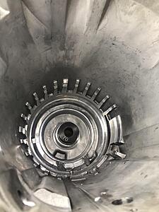
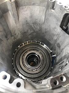
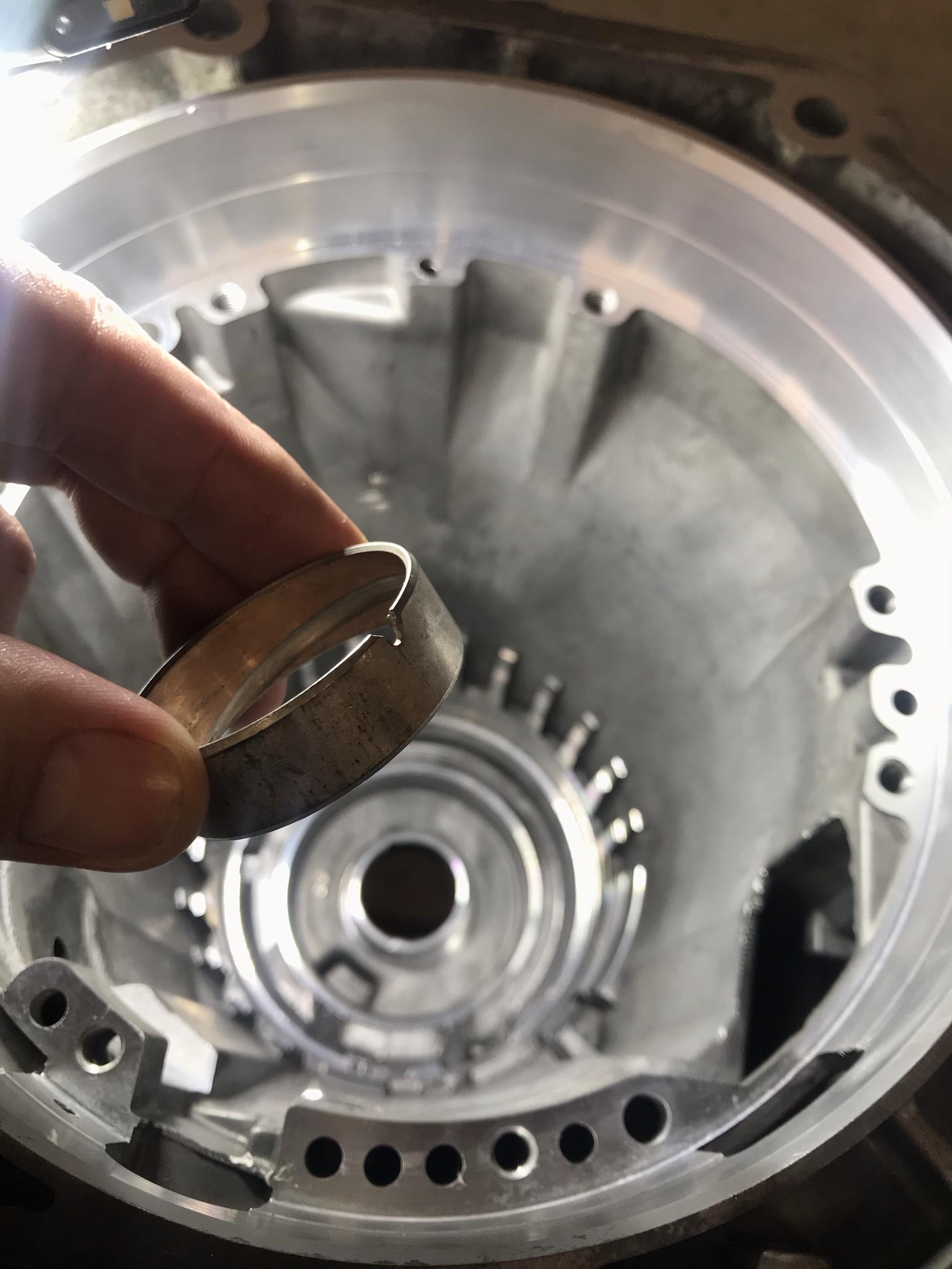
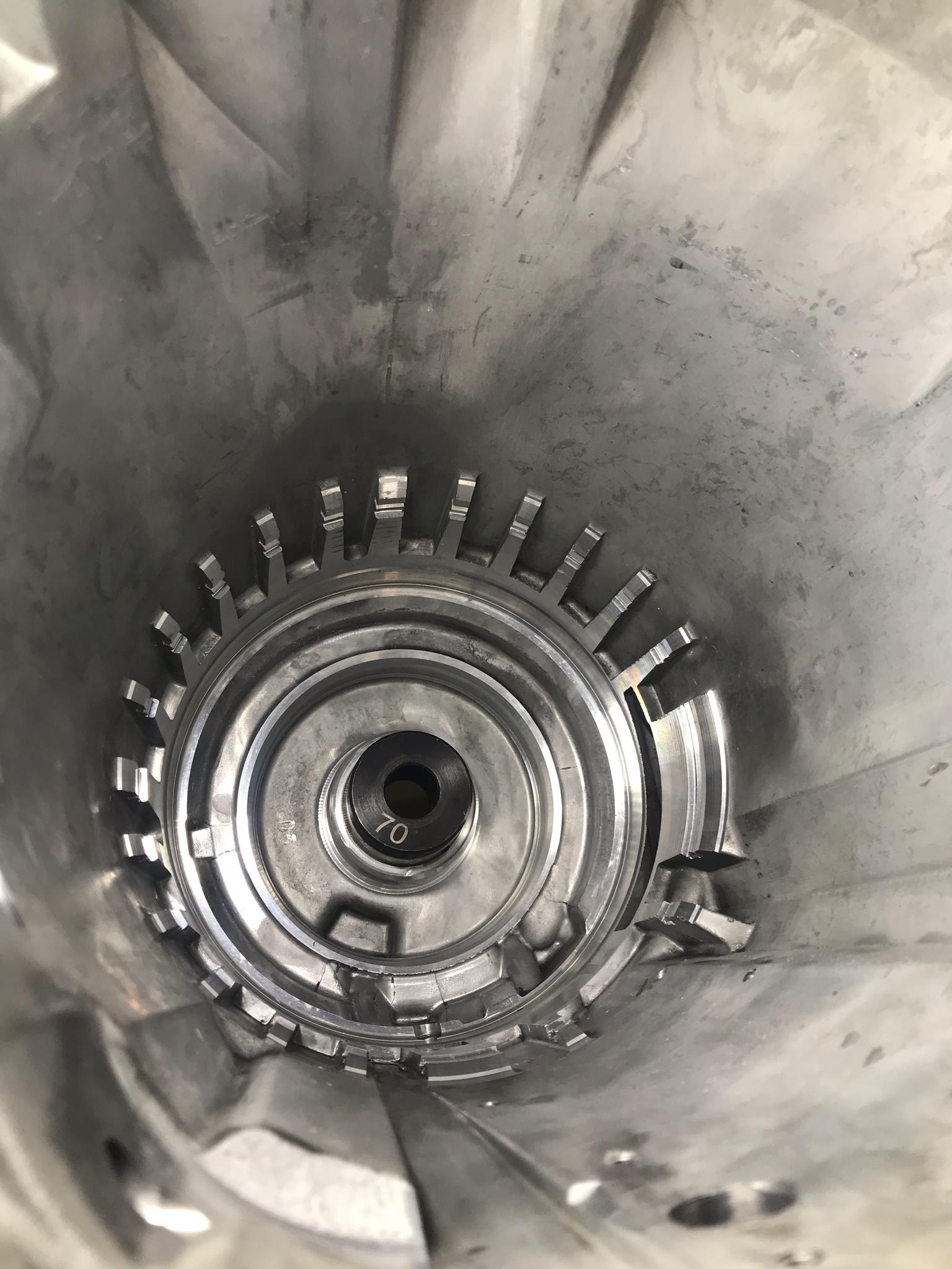
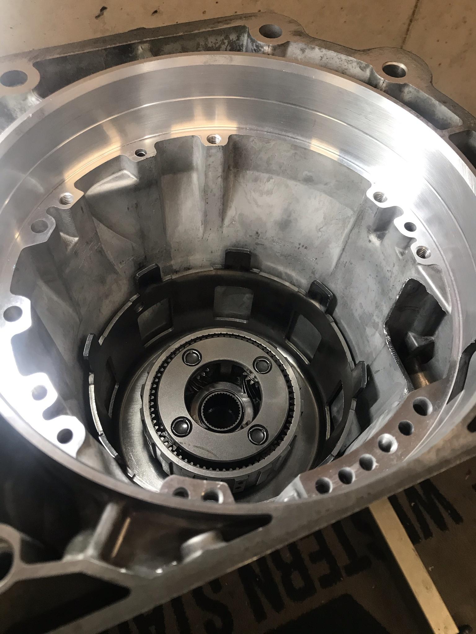
As you can see, I have the lower unit together. When installing the output shaft the shaft wouldnt come up far enough to get the snap ring on. It was lacking .020-.030 approx from allowing the snap ring to go in the groove. As I thought I knew I should of assembled the lower unit on the bench and tested fitment before assembling into the case, I then thought the only thing really that is different is the sunshell and reaction tube setup from factory. That said the 74602-01K reaction tube comes with a .030" shim that goes between the reaction gear and carrier bearing. I removed the shim and the output shaft snap ring does in fact now go in the groove and the output shaft installs fine. Per Sonnax the .140" thick bearing they provide will work with either 83-06 or 07 and input later carrier assy. I confirmed my input carrier is the 07 and later variety. I did get ahold of Sonnax yesterday asking a little more information regarding this and if in fact I have to run the shim or not? I mentioned I didnt see in my opinion that not running the shim would effect anything as the bearing goes in the tube fine and the carrier rides and spins on the bearing fine also. They did confirm for me I didnt in fact have to run the shim if this was causing output shaft installation issues. But I really couldnt get out of them why its there in the first place? The guy I was talking to seemed new and he was basically a middle man with the information. At the end of the day im cool if I dont have to have it and my output shaft goes in, but I would rather know why the shim is there in the first place if its really not needed like this case?
Also, the last build I did the output shaft had slight end play to it. This setup it doesnt seem I have near as much end play. Not sure this is a huge issue or not.
02-16-2021, 12:16 PM
#94
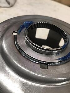
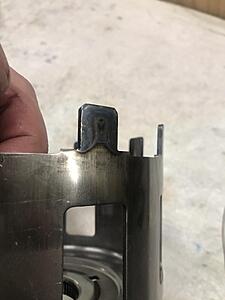
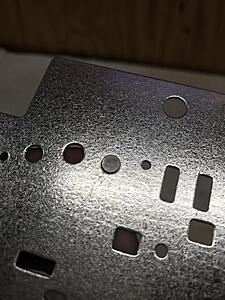
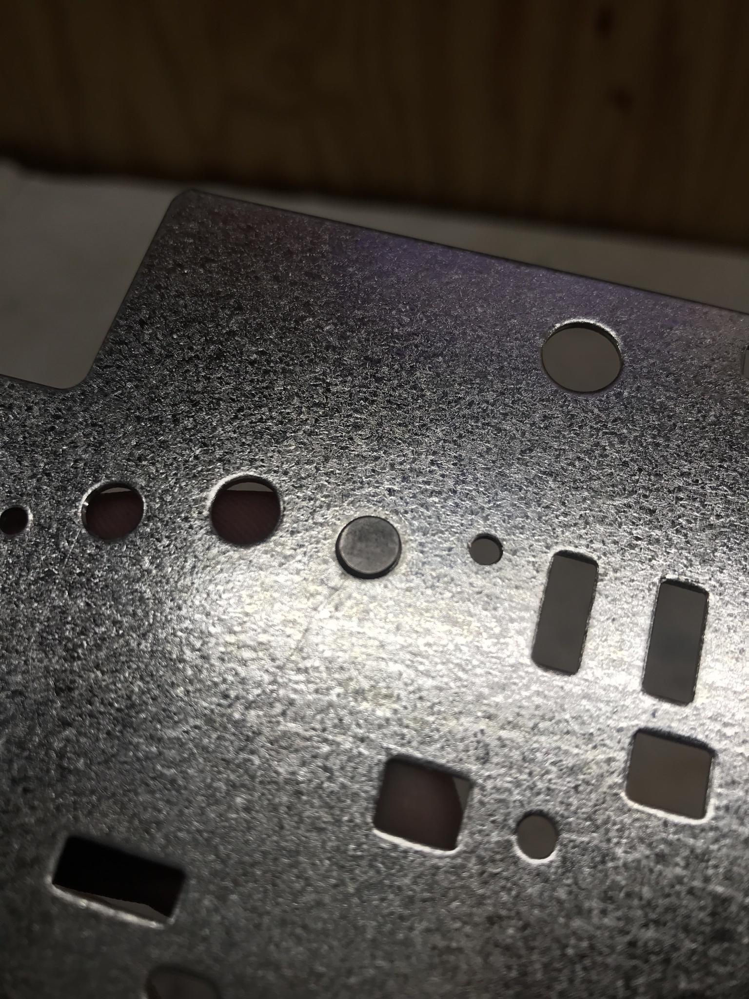
There is also something I want to have an educational discussion about. I noticed when I got my modified separator plate from Dana at Pro Built Automatics there was an insert by the "band release" orifice . I did ask Dana about this via text message (which isnt his preferred way of communicating ) his response was this "I starting doing this the past few years now depending on application as I work to address more of the engineered leaks in the transmission and adding the plug to this bleed hole will help even better depending on the application"
Now with that said, im not posting this to tell the world that you need to install a plug in this hole and it will address additional leaks on every trans. I do not think that is the case. What I would like to do is create an educational discussion regarding this to understand why this is done this way per my application. I hope Dana can elaborate more regarding this mod
Now with that said, im not posting this to tell the world that you need to install a plug in this hole and it will address additional leaks on every trans. I do not think that is the case. What I would like to do is create an educational discussion regarding this to understand why this is done this way per my application. I hope Dana can elaborate more regarding this mod
 02-16-2021, 12:35 PM
#95
TECH Junkie
The separator plate hole that is plugged, has nothing to do with leaking circuits.
If Dana is doing what I had discussed with him, then the following should be true:
-The #2 Check-Ball should be omitted.
-The hole for the #2 Check-Ball should be plugged.
-The Bleed hole for the #2 Check-Ball should be enlarged.
-The 3-2 Control Valve should be blocked.
-The 3rd Feed hole and Exhaust hole should be enlarged.
All of this has to do with the 2-3 shift timing (The 3rd Accumulator circuit).
02-16-2021, 12:37 PM
#96
TECH Junkie
Note: any plugs installed into the Separator Plate must be filled and sanded flush and smooth.
02-16-2021, 12:41 PM
#97
TECH Junkie
A few things here I have been running across during the build.
As you can see, I have the lower unit together. When installing the output shaft the shaft wouldnt come up far enough to get the snap ring on. It was lacking .020-.030 approx from allowing the snap ring to go in the groove. As I thought I knew I should of assembled the lower unit on the bench and tested fitment before assembling into the case, I then thought the only thing really that is different is the sunshell and reaction tube setup from factory. That said the 74602-01K reaction tube comes with a .030" shim that goes between the reaction gear and carrier bearing. I removed the shim and the output shaft snap ring does in fact now go in the groove and the output shaft installs fine. Per Sonnax the .140" thick bearing they provide will work with either 83-06 or 07 and input later carrier assy. I confirmed my input carrier is the 07 and later variety. I did get ahold of Sonnax yesterday asking a little more information regarding this and if in fact I have to run the shim or not? I mentioned I didnt see in my opinion that not running the shim would effect anything as the bearing goes in the tube fine and the carrier rides and spins on the bearing fine also. They did confirm for me I didnt in fact have to run the shim if this was causing output shaft installation issues. But I really couldnt get out of them why its there in the first place? The guy I was talking to seemed new and he was basically a middle man with the information. At the end of the day im cool if I dont have to have it and my output shaft goes in, but I would rather know why the shim is there in the first place if its really not needed like this case?
Also, the last build I did the output shaft had slight end play to it. This setup it doesnt seem I have near as much end play. Not sure this is a huge issue or not.
Please double check the instructions.
Please post a photo of the bearing that you have and the bearing surface on the planet that you have to confirm that everything matches.
02-16-2021, 01:04 PM
#99
TECH Junkie
Each type of carrier uses its own type of bearing (with a lip, or without a lip).
The shim is to add height to the carrier that uses a Non-Lipped bearing, in order to fit the reaction-shaft.
The purpose of this is to allow two different carriers/ bearings to fit one type of reaction-shaft... when normally two different reaction-shafts are used.

