When you click on links to various merchants on this site and make a purchase, this can result in this site earning a commission. Affiliate programs and affiliations include, but are not limited to, the eBay Partner Network.
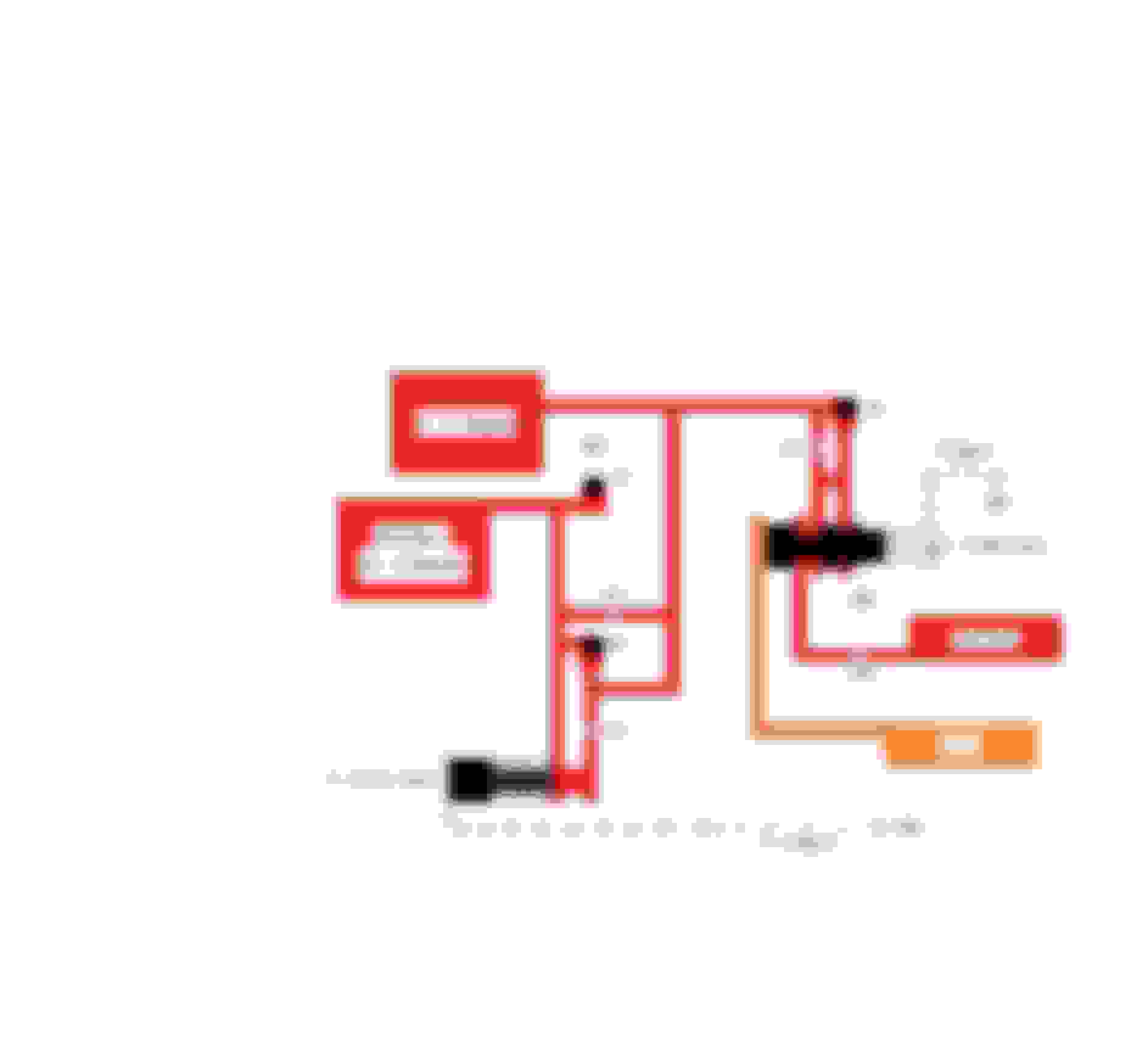
Here is a simplified diagram of the circuits involved for applying 3rd gear:
-Feed oil will pass through the 2-3 shift valve.
-Pass through the #4 check-ball passage (3rd Exhaust) and the #13 orifice.
-Then enter the 3-4 clutch pack.
-Fluid also branches-off, instead of just going to the 3-4 clutch (this is 3rd accumulator fluid).
-There are 3 paths for 3rd accumulator fluid to take to get to push-off the 2-4 servo and band.
-The #2 check-ball (3rd accumulator fluid)... *You have this plugged in your separator plate, eliminating 1 of 3 passages*.
-The #12 orifice.
-The #14 orifice if the 3-2 Control Valve passage is OPEN... *Yours should be blocked, eliminating 2 of 3 passages*.
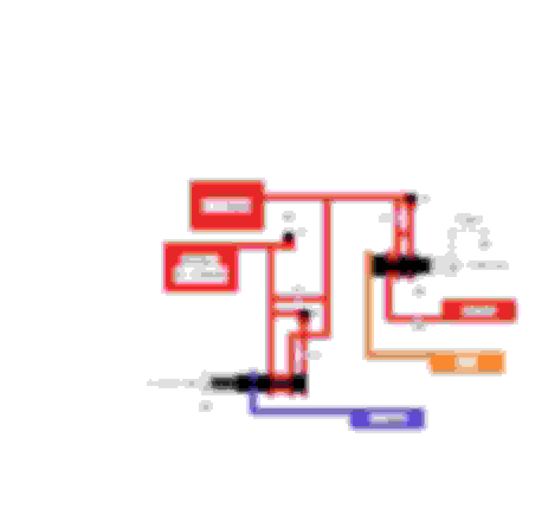
The 3-2 Control Valve was supposed to operate like a On/ Off switch on paper... It does not really do this.
The 3-2 Control Valve has been changed over the years to try and improve its function...
It originally operated as a variable orifice instead of an On/ Off switch... as I said the newer designs did improve on this.
However in a performance application, this valve does nothing to benefit the 2-3 shift.
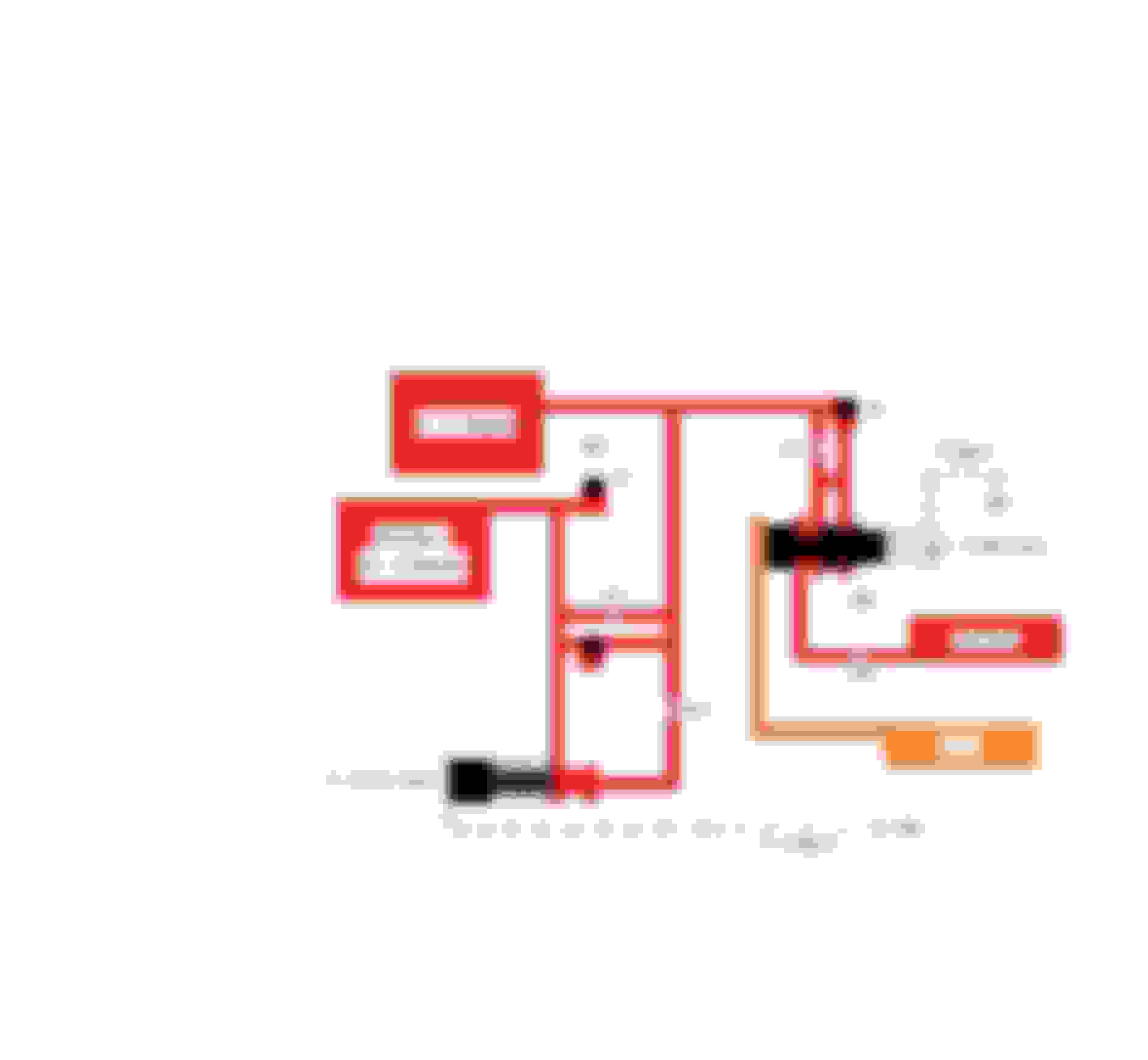
We end up with the #12 orifice being the ONLY passage to the 2-4 Servo.
We can size the orifice accordingly to control the 2-3 shift timing.
Keeping the #2 check-ball also is an option... and most builders tend to keep it...
calculating the #12 orifice size in combination with the #2 check-ball passage.
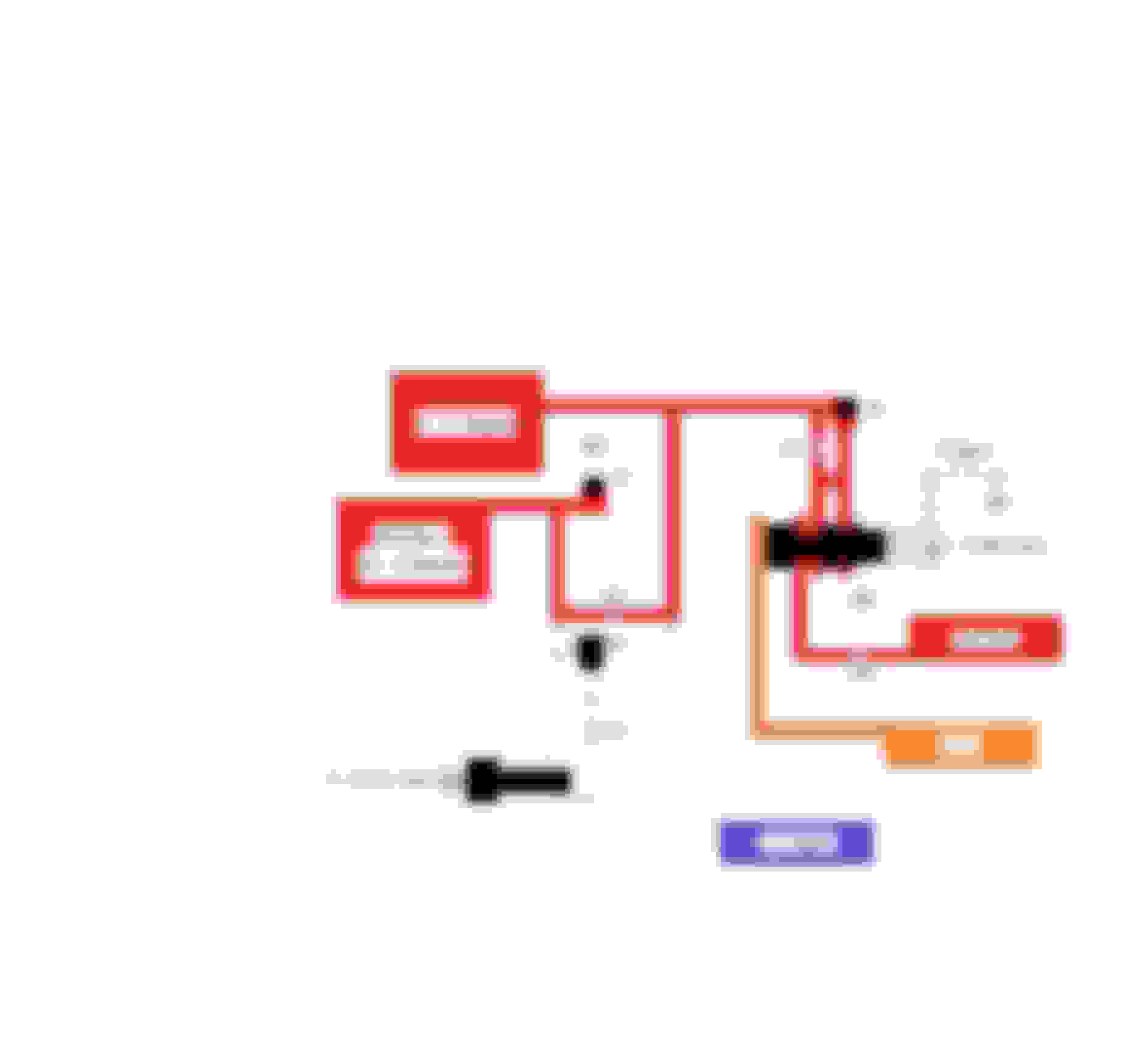
The modified diagram with ONLY the #12 orifice looks like this:
You can NOT use the same bearing with two different carriers.
Each type of carrier uses its own type of bearing (with a lip, or without a lip).
The shim is to add height to the carrier that uses a Non-Lipped bearing, in order to fit the reaction-shaft.
The purpose of this is to allow two different carriers/ bearings to fit one type of reaction-shaft... when normally two different reaction-shafts are used.
The carriers you are showing are GM carriers which they are different. I have the Sonnax carrier?
And wow....that diagram explaining the plug for the separator plate is GOLD! Makes total sense now.
Now, that said. I assume this wouldnt be for every build? Just asking here but I assume it would depend on what size servos one has, size band, as well as knowing if there are any leaks in the VB due to wear? As well as blocking both 3-2 valves ect.?
The hole that is slugged is 29F (lower left corner where the checkball is shown)
29g is not slugged (looks like this is what you call #14??)
With the 3-2 control blocked inboard (or with the solenoid on) the only route for oil to 3rd accum is 29g
Vortec, I'm not sure I agree with your simplified oil diagram.
29g is still going to let oil hit the 3-2 control valve stem.
And 29g will also be what delivers oil to the 3rd accum circuit.
29c (what I think you call #12??) will also still deliver oil to the 3-2 control
I think you have 12 and 14 flipped in your diagram
And the slug for #2 blocks only the checkball, not the accompanying orifice
Basically, it looks like the slug will just change a checkball'd circuit to a fixed orifice circuit
Look at the numbers in the small blue circles, not the separator plate hole numbers.
-12 is near the #2 check-ball and goes to one side of the 3-2 control-valve.
-13 is near the #4 check-ball.
-14 is the 29c orifice, and goes to the other side of the 3-2 control-valve.
Do not look at the "Complete" hydraulic diagram that you posted to compare to my diagram...
This diagram can be simplified, as paths that go nowhere with a blocked 3-2 Control-Valve can be eliminated.
This is shown in the "Partial" hydraulic diagram, like the Overdrive range third gear diagram in figure 50.
@vorteciroc Yes I know I have the Sonnax tube. I havnt had the chance to get pictures of the carrier and bearing but im 99% positive I have the 07 & later carrier and the no lip bearing thats 2.540 OD, 1.680 ID, and .140" thick which this bearing came with the reaction tube.
With that said, the 2007 and later carrier I can either run the no lip bearing or the bearing with the lip. According to the instructions the no lip is .140" thick with a .030" shim which would total .170" thick. I CANT get my snap ring on the output shaft with this stack up. If I take the .030" shim out, I CAN get the snap ring on the output shaft. I called Sonnax to confirm this is ok and they did confirm its ok?
If I would run the bearing with the lip im going to have a thicker stack up as the bearing with the lip will be thicker than the bearing with no lip and shim. So im going backwards here and I def wouldnt be able to get the snap ring on the output shaft.
With the 2007 and later carrier I can run either bearing and shim, or bearing with lip.
The 2007 and UP front Carrier/ Planet needs a Bearing WITH the Lip... No 0.030" shim will be used.
" 3. For Late 2007–Later: 4 & 5 pinion input carriers choose option 1 or option 2. This kit includes .140" thick reaction shaft-to-front
carrier bearing for option 1 and does NOT include .170" thick bearing for reaction shaft-to-front carrier bearing for option 2 (Figure 4).
Pay attention to the part in RED... This is your configuration... and the bearing is not included.
The bearing with no lip centers fine in the sonnax tube.
It doesn't rely on the carrier to center
Run the supplied bearing with the shim. It works with everything.
If you can't get the output shaft snap ring on..
A. make sure the stackup is correct with the sunshell and bearing.
B. Try harder...sometimes they're a real bugger to get installed. There is a GM/Kent Moore tool to support the output towards the pump while you install snap ring. A properly placed ratchet strap with light tension works just as well for the DIY guy
Look at the numbers in the small blue circles, not the separator plate hole numbers.
-12 is near the #2 check-ball and goes to one side of the 3-2 control-valve.
-13 is near the #4 check-ball.
-14 is the 29c orifice, and goes to the other side of the 3-2 control-valve.
Do not look at the "Complete" hydraulic diagram that you posted to compare to my diagram...
This diagram can be simplified, as paths that go nowhere with a blocked 3-2 Control-Valve can be eliminated.
This is shown in the "Partial" hydraulic diagram, like the Overdrive range third gear diagram in figure 50.
The first diagrams showed the 3-2 being totally divorced from the rest of the oil. I thought you were implying that was the change that occured when the hole in the plate was blocked like 2BFAST posted
Ultimately, the gist of what I was saying is that blocking that checkball is only going to change the delivery rate of oil to the 3rd accum.
There will be no other appreciable difference
Block the 3-2 downshift and 3-2 control to remove their unneeded complexity and leaks. Leave the checkball active. My $0.02 is that having maximum flow to the 3rd accum is a good thing. Choking it down to a single orifice is not beneficial when the other modifications have occured.
This will be further evident if you move from a "corvette" servo to a sonnax billet servo or superior servo etc. Because they have less release bias and need more to release the band on a 2-3.
If a customer was experiencing a flare that couldn't be otherwise solved, then blocking checkball and restricting the servo release oil to allow the 3/4's time to apply might be a valid modification.
@PBA care to chime in on your methods/reasons for blocking the check ball hole? Maybe you see a benefit I'm overlooking
The bearing with no lip centers fine in the sonnax tube.
It doesn't rely on the carrier to center
Run the supplied bearing with the shim. It works with everything.
If you can't get the output shaft snap ring on..
A. make sure the stackup is correct with the sunshell and bearing.
B. Try harder...sometimes they're a real bugger to get installed. There is a GM/Kent Moore tool to support the output towards the pump while you install snap ring. A properly placed ratchet strap with light tension works just as well for the DIY guy
The Sonnax supplied bearing centers fine on the reaction-shaft.
The bearing fitment to the carrier is however poor... The original GM bearing with the Lip is a better fit.
Unless you are saying, that the supplied bearing ONLY fits with the 0.030" shim?
I was referring to the fitment without the 0.030" shim.
The first diagrams showed the 3-2 being totally divorced from the rest of the oil. I thought you were implying that was the change that occured when the hole in the plate was blocked like 2BFAST posted
Ultimately, the gist of what I was saying is that blocking that checkball is only going to change the delivery rate of oil to the 3rd accum.
There will be no other appreciable difference
Block the 3-2 downshift and 3-2 control to remove their unneeded complexity and leaks. Leave the checkball active. My $0.02 is that having maximum flow to the 3rd accum is a good thing. Choking it down to a single orifice is not beneficial when the other modifications have occured.
This will be further evident if you move from a "corvette" servo to a sonnax billet servo or superior servo etc. Because they have less release bias and need more to release the band on a 2-3.
If a customer was experiencing a flare that couldn't be otherwise solved, then blocking checkball and restricting the servo release oil to allow the 3/4's time to apply might be a valid modification.
@PBA care to chime in on your methods/reasons for blocking the check ball hole? Maybe you see a benefit I'm overlooking
I have had no issues with any of the Aftermarket Servos... The Band-Release orifice just needs to be sized accordingly.
This orifice becomes quite large when being used alone...
The reason that I prefer this method, is that I feel that it produces more consistent 2-3 shifts in my units... vs keeping the #2 check-ball and passage with a smaller band release orifice.
Last edited by vorteciroc; 02-17-2021 at 04:08 PM.


 02-16-2021, 02:35 PM