

'70 Nova LY6/TH400 6.0VVT
 07-22-2013 | 03:54 PM
#861
Thread Starter
TECH Addict
iTrader: (1)
Joined: Apr 2010
Posts: 2,816
Likes: 84
From: Instagram @chevyhotrodder
Thanks guys! I really like having that naked space between the valve covers and the fuel rails. It would have been nice to fully tuck the wiring under the cover, but this is a good compromise. I can fish the loom under the fuel rail for R&R of the intake in the future without much hassle.
On the driver's side, I have to deal with the transmission dipstick, so it may not turn out quite as clean, but there is other clutter there like the brake booster and wiper motor to provide cover/distraction.
On the driver's side, I have to deal with the transmission dipstick, so it may not turn out quite as clean, but there is other clutter there like the brake booster and wiper motor to provide cover/distraction.
07-22-2013 | 06:11 PM
#862

TECH Senior Member

Joined: Jul 2009
Posts: 7,927
Likes: 608
www.Wirecare.com is ANOTHER source for assorted loom. They have the silver high temp wrap thats typically used on the knock sensors.
07-24-2013 | 12:13 AM
#863
Thread Starter
TECH Addict
iTrader: (1)
Joined: Apr 2010
Posts: 2,816
Likes: 84
From: Instagram @chevyhotrodder
Continuing work, here is one more shot of the passenger side in its current state. It should look good when all the AC stuff is cleaned up.

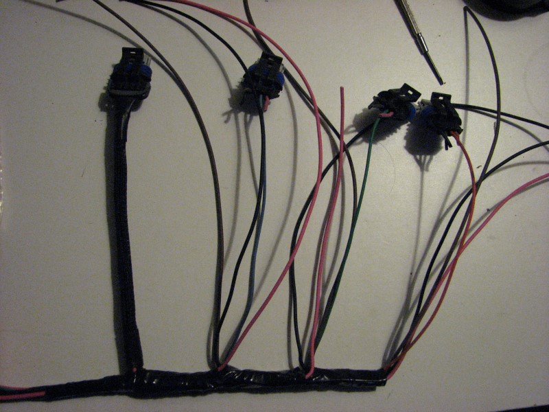
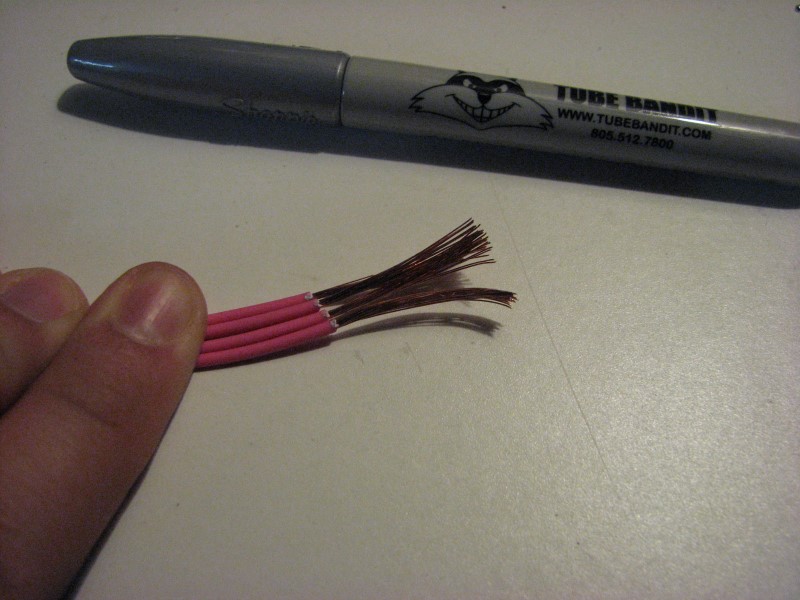
Tonight I got most of the driver's side injector harness done in about 2 hours. I had to replace the no 1 injector trigger wire because it was too short. It will be the only injector with 18gauge on both the ECM trigger and +12volts (factory I think is 20gauge). Also all the +12volt wires are new. Unfortunately I do not have pink/blk for this bank like the factory, so I will have to keep track of which pink wires are for bank 1 vs bank 2 to fuse them separately.

Tonight I got most of the driver's side injector harness done in about 2 hours. I had to replace the no 1 injector trigger wire because it was too short. It will be the only injector with 18gauge on both the ECM trigger and +12volts (factory I think is 20gauge). Also all the +12volt wires are new. Unfortunately I do not have pink/blk for this bank like the factory, so I will have to keep track of which pink wires are for bank 1 vs bank 2 to fuse them separately.
Last edited by -TheBandit-; 07-24-2013 at 10:33 AM.
07-26-2013 | 10:22 PM
#864
Thread Starter
TECH Addict
iTrader: (1)
Joined: Apr 2010
Posts: 2,816
Likes: 84
From: Instagram @chevyhotrodder
Finished that part of the harness last night.


Originally I was thinking I would run the mechanical coolant temp gauge I already have. Below is how I planned to route the sensing bulb. There is a nice area on the backside of the waterpump outlet where you could tap for a sensor. The capillary tube fits between the intake and valley cover so it would stay hidden. But I think I am going to use CAN gauges from Speedhut instead.


Originally I was thinking I would run the mechanical coolant temp gauge I already have. Below is how I planned to route the sensing bulb. There is a nice area on the backside of the waterpump outlet where you could tap for a sensor. The capillary tube fits between the intake and valley cover so it would stay hidden. But I think I am going to use CAN gauges from Speedhut instead.
07-31-2013 | 11:27 PM
#866
Thread Starter
TECH Addict
iTrader: (1)
Joined: Apr 2010
Posts: 2,816
Likes: 84
From: Instagram @chevyhotrodder
I've started working on the coil harness. This is a real challenge because each coil has four wires, three of which get joined in sets of four (12+, ground and signal ground). Each of those junctions essentially has five wires connected (1 in, 4 out) which presents quite a challenge. I have played with a number of different ways to join wires and ultimately decided on this method.
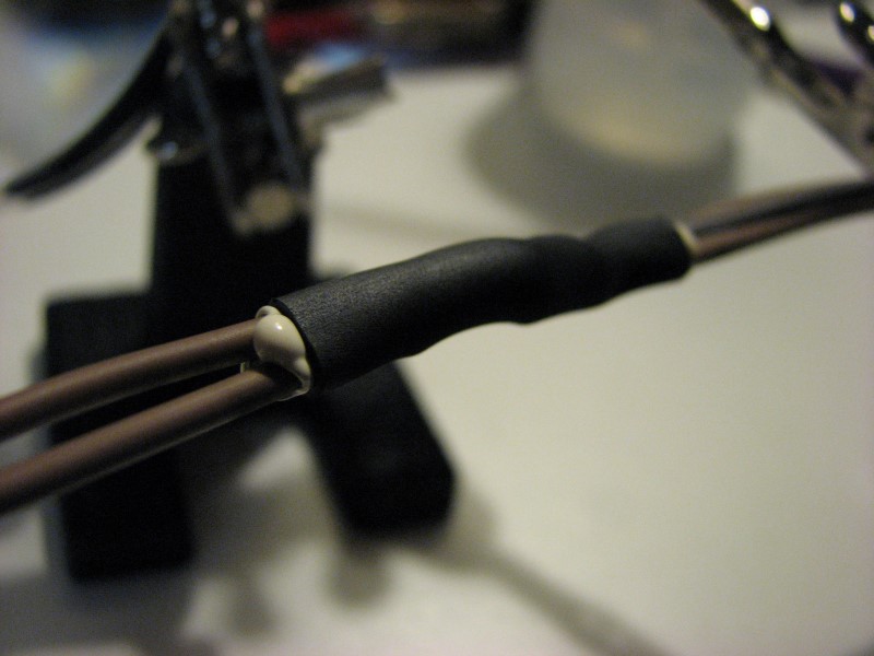
The following photos show a practice run on scrap wire. The first step is stripping the ends of four wires about 1". I do not twist the strands at all at this point.
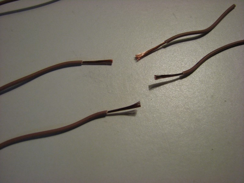
Next I joined pairs of wires by twising them around eachother. I start by putting a slight bend in both wires about half way, hook them with eachother, then carefully wrap the strands.
After that, I put the four wires into an X and then twist them around eachother in the same direction.

Last comes the "input" wire. I strip a lot of insulation off this one, about 2", to give plenty of strand length for wrapping.

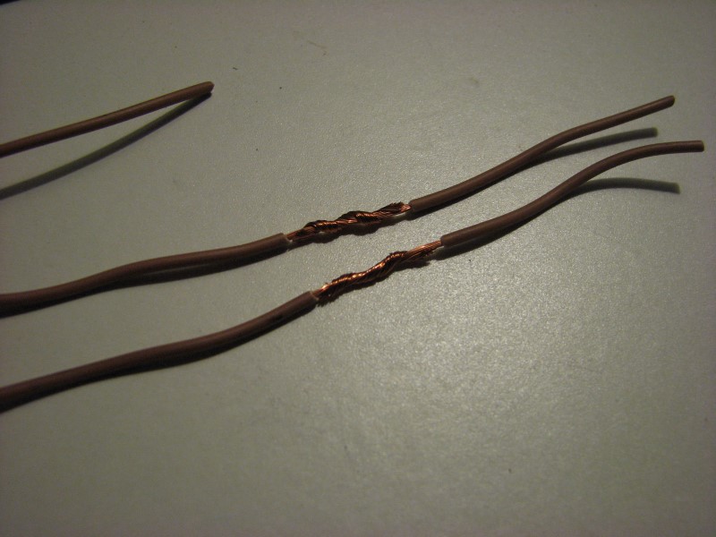
It then gets wrapped around the others, again working in the same direction. The finished wrap is shown below. I can tug on each of the individual wires and they don't budge. This joint is ready for solder.

I worked hard to find the original Delphi adhesive shrink wrap that is used on the factory harness. It is Delphi PN 12186167. They are 2.5" long. I bought a bunch from Mouser. http://www.mouser.com/Search/m_Produ...EaDdmQhlpZiPA=

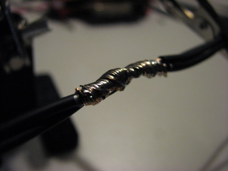
Now to make my first actual junction. I followed the same sequence as above. This is for the signal ground for the odd cylinders.


The solder joint wasn't awesome, but the solder did wick around all the strands after it was heated. It really took some time to heat up with the little iron I was using. This is a big joint.
And here is the start the coil harness for the first four (odd bank) coils.


This is going to be a lot of work!
The following photos show a practice run on scrap wire. The first step is stripping the ends of four wires about 1". I do not twist the strands at all at this point.
Next I joined pairs of wires by twising them around eachother. I start by putting a slight bend in both wires about half way, hook them with eachother, then carefully wrap the strands.
After that, I put the four wires into an X and then twist them around eachother in the same direction.
Last comes the "input" wire. I strip a lot of insulation off this one, about 2", to give plenty of strand length for wrapping.
It then gets wrapped around the others, again working in the same direction. The finished wrap is shown below. I can tug on each of the individual wires and they don't budge. This joint is ready for solder.
I worked hard to find the original Delphi adhesive shrink wrap that is used on the factory harness. It is Delphi PN 12186167. They are 2.5" long. I bought a bunch from Mouser. http://www.mouser.com/Search/m_Produ...EaDdmQhlpZiPA=
Now to make my first actual junction. I followed the same sequence as above. This is for the signal ground for the odd cylinders.
The solder joint wasn't awesome, but the solder did wick around all the strands after it was heated. It really took some time to heat up with the little iron I was using. This is a big joint.
And here is the start the coil harness for the first four (odd bank) coils.
This is going to be a lot of work!
Last edited by -TheBandit-; 08-01-2013 at 10:20 AM.


 08-02-2013 | 10:39 PM
#870
Thread Starter
TECH Addict
iTrader: (1)
Joined: Apr 2010
Posts: 2,816
Likes: 84
From: Instagram @chevyhotrodder
Thanks guys!
Thanks for the idea. I looked into this and I decided to get one. I ordered a Portasol 125 watt kit that includes several soldering tips, a hot knife and a hot air blower for heat shrink. That should help a bunch since I've been doing all this with a butane lighter so far. I love tools.
As tedious and time consuming as the wiring has been, so far this has been my favorite part of the build. Assembling the short block was a close second.
As tedious and time consuming as the wiring has been, so far this has been my favorite part of the build. Assembling the short block was a close second.
08-03-2013 | 03:07 AM
#871
 08-11-2013 | 11:19 PM
#873
Thread Starter
TECH Addict
iTrader: (1)
Joined: Apr 2010
Posts: 2,816
Likes: 84
From: Instagram @chevyhotrodder
Continuing work on the coil harness... I picked up a Portasol 125w butane soldering iron and wow, that was a great idea! The 50w Weller I've used for electronics soldering has always worked great, but it's just not powerful enough for this type of joint.


The odd bank coils and junctions went together nicely. Once I had all three junctions done, I laid them on top of the trigger wires which I had already setup to the desire length and tee-off location.

Then I wrapped the main run to get things bundled. I was surprised to find the wrapped section wasn't very big despite the junctions.
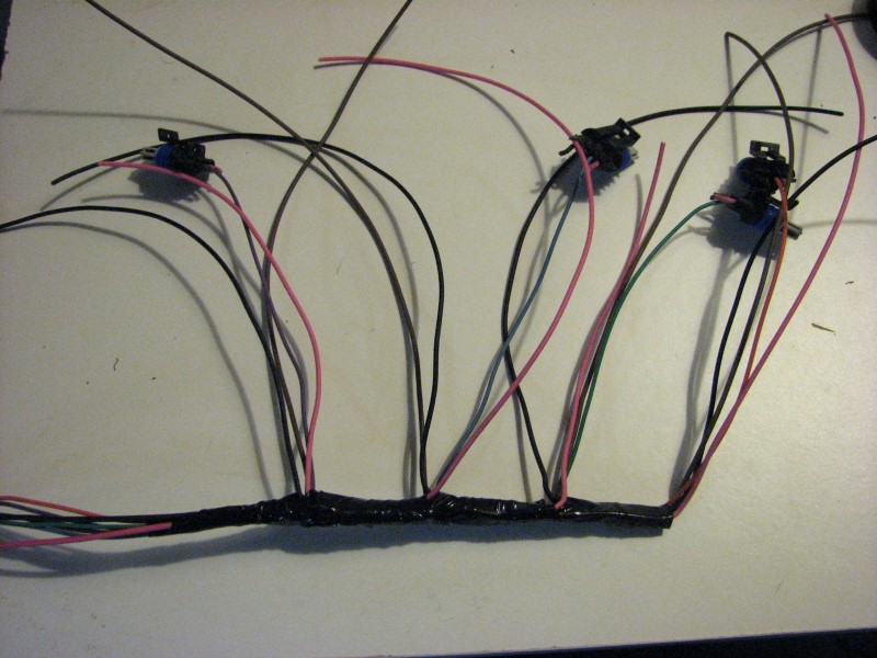
I left excess on each of the junction wires and cut them to length afterwards.
Then I added terminals, loom and heat shrink for the individual coil lengths, put the terminals in the connectors, and shrunk the ends. I used no harness wrap on these short runs and picked the smallest diameter loom I could, which doesn't have much overlap.
I was also in an in-between heat shrink size, so the resulting 2:1 shrink ended up open-mouth with some curl on the ends. I'm thinking about redoing the shrink on these with either a smaller size (hard to get on) or 3:1.

Now that I have the first section done, the other 4 coils should go a bit faster.
Can anyone think of what circuits I might want to ground to the back of the driver's side head? So far I have just the coils. I'm thinking about also joining the OBDII ground there, but not sure what else. The main ECM ground and the MAF are grounded to front of the passenger head. Am I missing any?
Here is a link to the wiring diagram I am working from: http://cjnn.xtremefabricator.com/lsx...sSchematic.JPG
The odd bank coils and junctions went together nicely. Once I had all three junctions done, I laid them on top of the trigger wires which I had already setup to the desire length and tee-off location.
Then I wrapped the main run to get things bundled. I was surprised to find the wrapped section wasn't very big despite the junctions.
I left excess on each of the junction wires and cut them to length afterwards.
Then I added terminals, loom and heat shrink for the individual coil lengths, put the terminals in the connectors, and shrunk the ends. I used no harness wrap on these short runs and picked the smallest diameter loom I could, which doesn't have much overlap.
I was also in an in-between heat shrink size, so the resulting 2:1 shrink ended up open-mouth with some curl on the ends. I'm thinking about redoing the shrink on these with either a smaller size (hard to get on) or 3:1.
Now that I have the first section done, the other 4 coils should go a bit faster.
Can anyone think of what circuits I might want to ground to the back of the driver's side head? So far I have just the coils. I'm thinking about also joining the OBDII ground there, but not sure what else. The main ECM ground and the MAF are grounded to front of the passenger head. Am I missing any?
Here is a link to the wiring diagram I am working from: http://cjnn.xtremefabricator.com/lsx...sSchematic.JPG
08-12-2013 | 11:18 AM
#875

[quote=-TheBandit-;17610030]
Can anyone think of what circuits I might want to ground to the back of the driver's side head? /quote]
Do yourself a favor right now and add grounds... LOTS of em. IIRC theres about 15 grounds on my last build. I add more each time and each time I build? I get less post build gremlins. 9/10 if theres an issue with an electrical circuit in a car its a grounding issue. Run from engine to K member, Batt to engine, Batt to body, engine + batt to ECM, Fuse/relay pack to engine, etc. etc. Pretty much anywhere you can sneak a ground in there without making it obviously ugly is very wise. Dont rely on the cars metal to do all the work. Help out everywhere and anywhere you can by adding in grounds.
Getting close man, lets hear some rumble already
08-13-2013 | 12:17 AM
#877
Thread Starter
TECH Addict
iTrader: (1)
Joined: Apr 2010
Posts: 2,816
Likes: 84
From: Instagram @chevyhotrodder
Thanks guys! Means a lot from you.
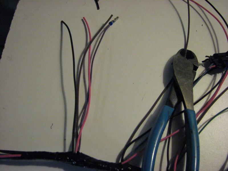
I finished up the 3 junctions for the even bank coils tonight. It took about an hour now that I have the hang of it.
First, the signal ground junction. For both the signal ground and the main ground I used the original wire from the old harness leading up to the junction, then new 18g from there to each coil. The main ground is 16g while the signal ground is 20g. Except for the +12v line, I reused all the input lines so I could keep the factory wire colors and ECM terminals. This helped maintain colors so I didn't have to buy a bunch of striped wire. The even bank has the same colors as the odd bank, but with white stripes. Here are the wire strands wrapped, soldered and sealed.


Here is the ground junction.


Here is the method used for the 4 coil wires coming off each junction. I started by marking the wires to get a consistent strip length.

Once stripped, I put about a 45 degree bend midway along the strands. This positions them for twisting.


Once they are twisted up, if there are strands overlapping the insulation as above, I pull the wires apart. With enough tension, they slide along one another. Next up, solder and shrink. I love this butane soldering iron!

I was really excited to have a heat tip with deflector for the butane soldering iron which is meant for doing shrink tube, but in practice I am trying to complete one joint and move to the next, so the solder tip is still way too hot to remove in time to replace with the heat shrink tip. So instead I used a butane lighter to shrink the tube. As mentioned above this is the Delphi adhesive tube that's used on the factory harness. It takes a while after it's already shrunk before the adhesive starts to ooze out.

And there they are, done done done!

I finished up the 3 junctions for the even bank coils tonight. It took about an hour now that I have the hang of it.
First, the signal ground junction. For both the signal ground and the main ground I used the original wire from the old harness leading up to the junction, then new 18g from there to each coil. The main ground is 16g while the signal ground is 20g. Except for the +12v line, I reused all the input lines so I could keep the factory wire colors and ECM terminals. This helped maintain colors so I didn't have to buy a bunch of striped wire. The even bank has the same colors as the odd bank, but with white stripes. Here are the wire strands wrapped, soldered and sealed.
Here is the ground junction.
Here is the method used for the 4 coil wires coming off each junction. I started by marking the wires to get a consistent strip length.
Once stripped, I put about a 45 degree bend midway along the strands. This positions them for twisting.
Once they are twisted up, if there are strands overlapping the insulation as above, I pull the wires apart. With enough tension, they slide along one another. Next up, solder and shrink. I love this butane soldering iron!
I was really excited to have a heat tip with deflector for the butane soldering iron which is meant for doing shrink tube, but in practice I am trying to complete one joint and move to the next, so the solder tip is still way too hot to remove in time to replace with the heat shrink tip. So instead I used a butane lighter to shrink the tube. As mentioned above this is the Delphi adhesive tube that's used on the factory harness. It takes a while after it's already shrunk before the adhesive starts to ooze out.
And there they are, done done done!
Last edited by -TheBandit-; 08-13-2013 at 09:54 AM.
08-13-2013 | 11:21 AM
#879
I reused the wiring, unmodified, just tucked the excess loom behind the manifold.. not nearly as sanitary as yours. Also, mine are mounted off the back of the block, so they look like they're 'floating' on the firewall. Same area as you/Speedtech tho.
08-13-2013 | 02:02 PM
#880
Thread Starter
TECH Addict
iTrader: (1)
Joined: Apr 2010
Posts: 2,816
Likes: 84
From: Instagram @chevyhotrodder
You must have done a nice job tucking the wires; I never would have known looking at your photos. I really like the symmetry in your setup. Mine are shifted off center for the wiper motor and that really bugs me visually, but I am getting over it. I can't remember - did you remove your wiper motor or relocate it?
Here a few examples of mounting coils in this area. The look has really grown on me.
frojoe's

Speed-tech Project Resurrextion

Mine:
Here's another one I came across on a '78 TA that looks simlar. Build thread here. I assume he used loom to recover the existing harness.

Here a few examples of mounting coils in this area. The look has really grown on me.
frojoe's
Speed-tech Project Resurrextion
Mine:
Here's another one I came across on a '78 TA that looks simlar. Build thread here. I assume he used loom to recover the existing harness.
Last edited by -TheBandit-; 08-13-2013 at 02:13 PM.