
88 Fiero Formula LS4/F40 6 speed swap
 06-12-2020, 08:18 PM
#341


When you have the first rail done, you have a template, but you also have to make both sides match... So in the end, the other side isn't really any quicker...
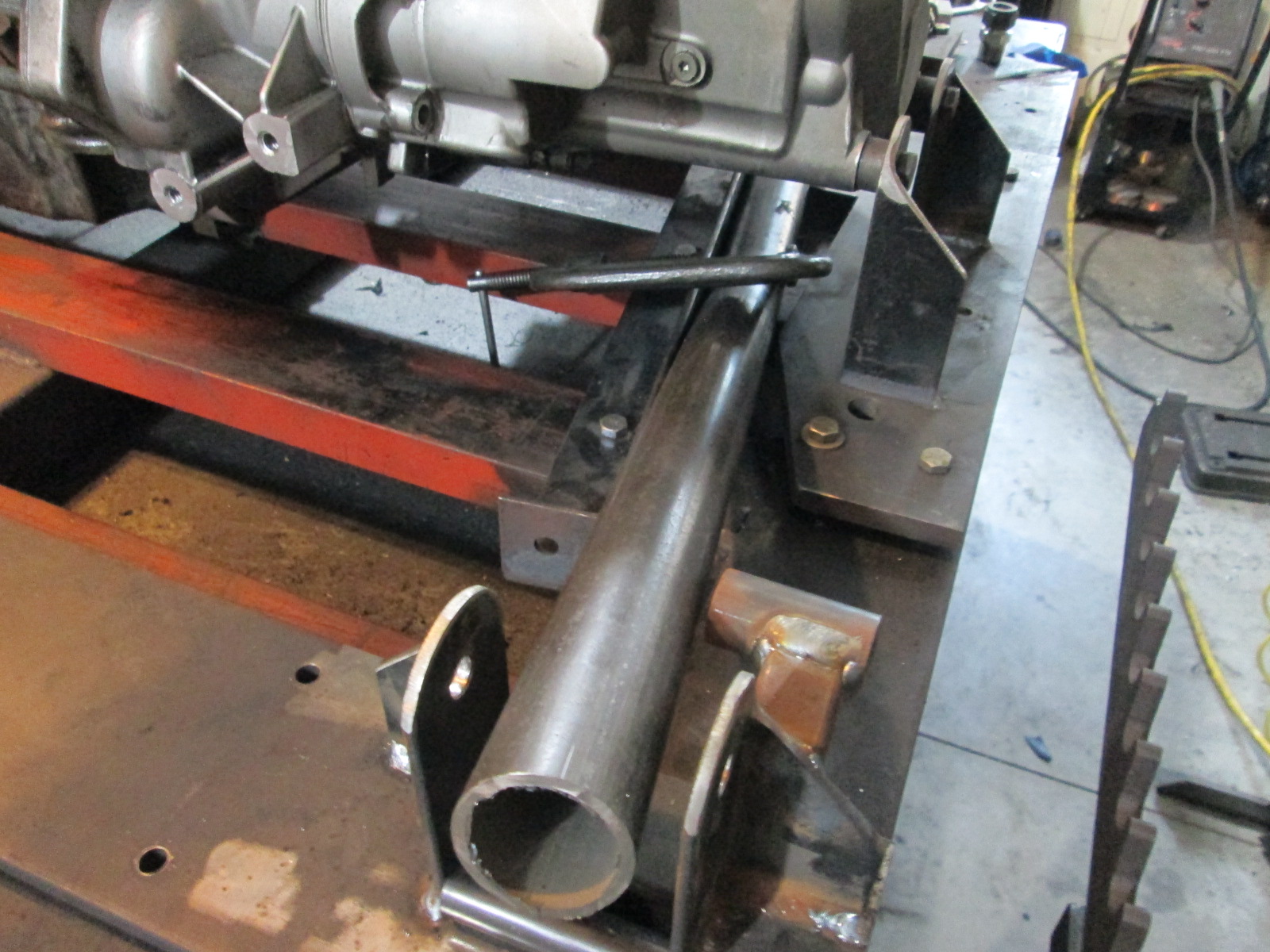
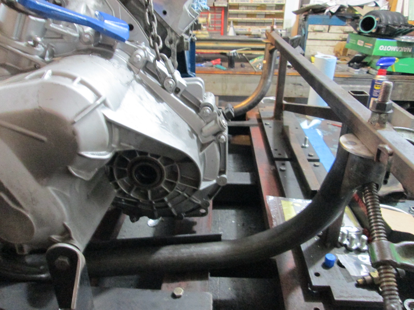
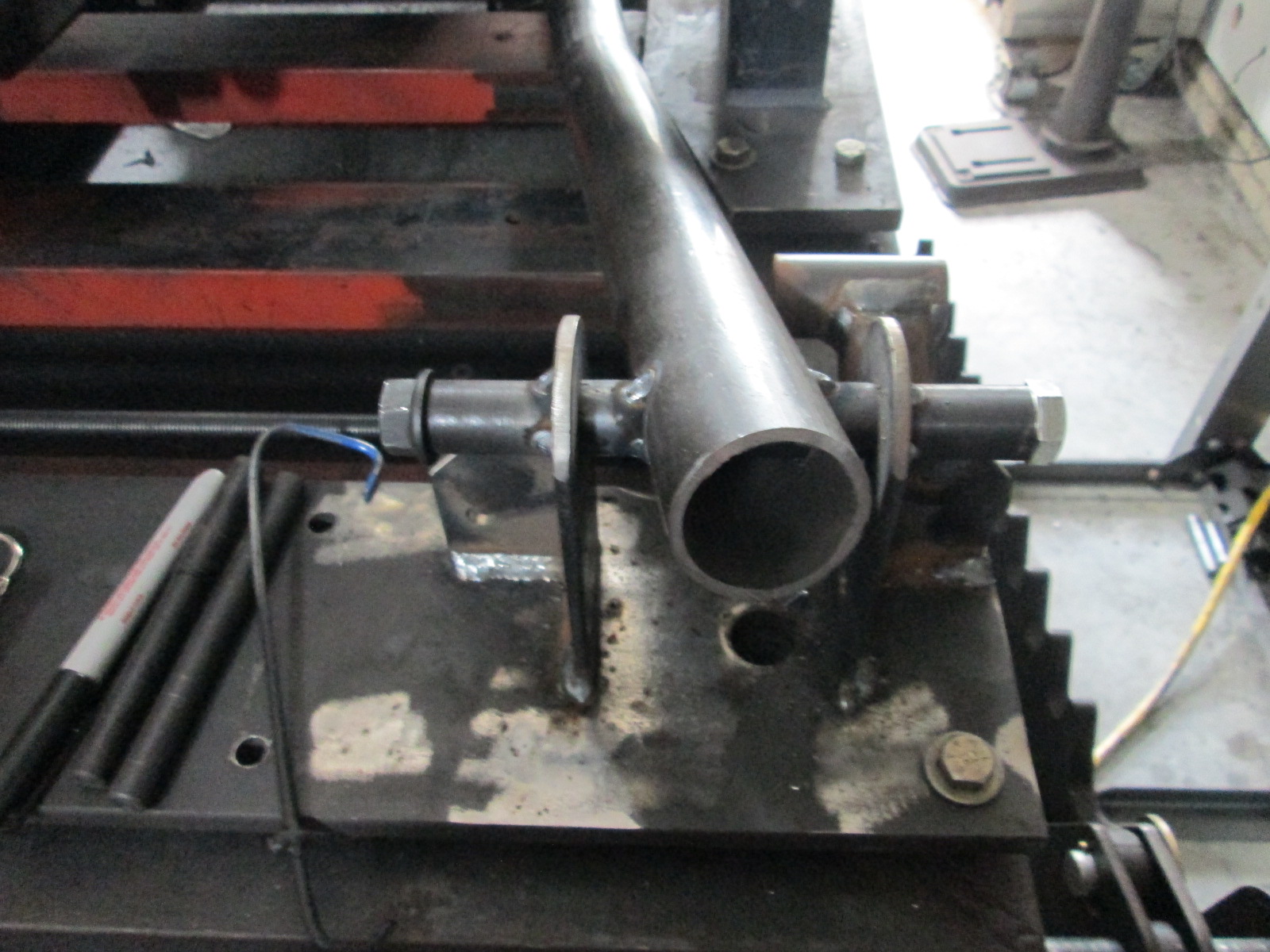
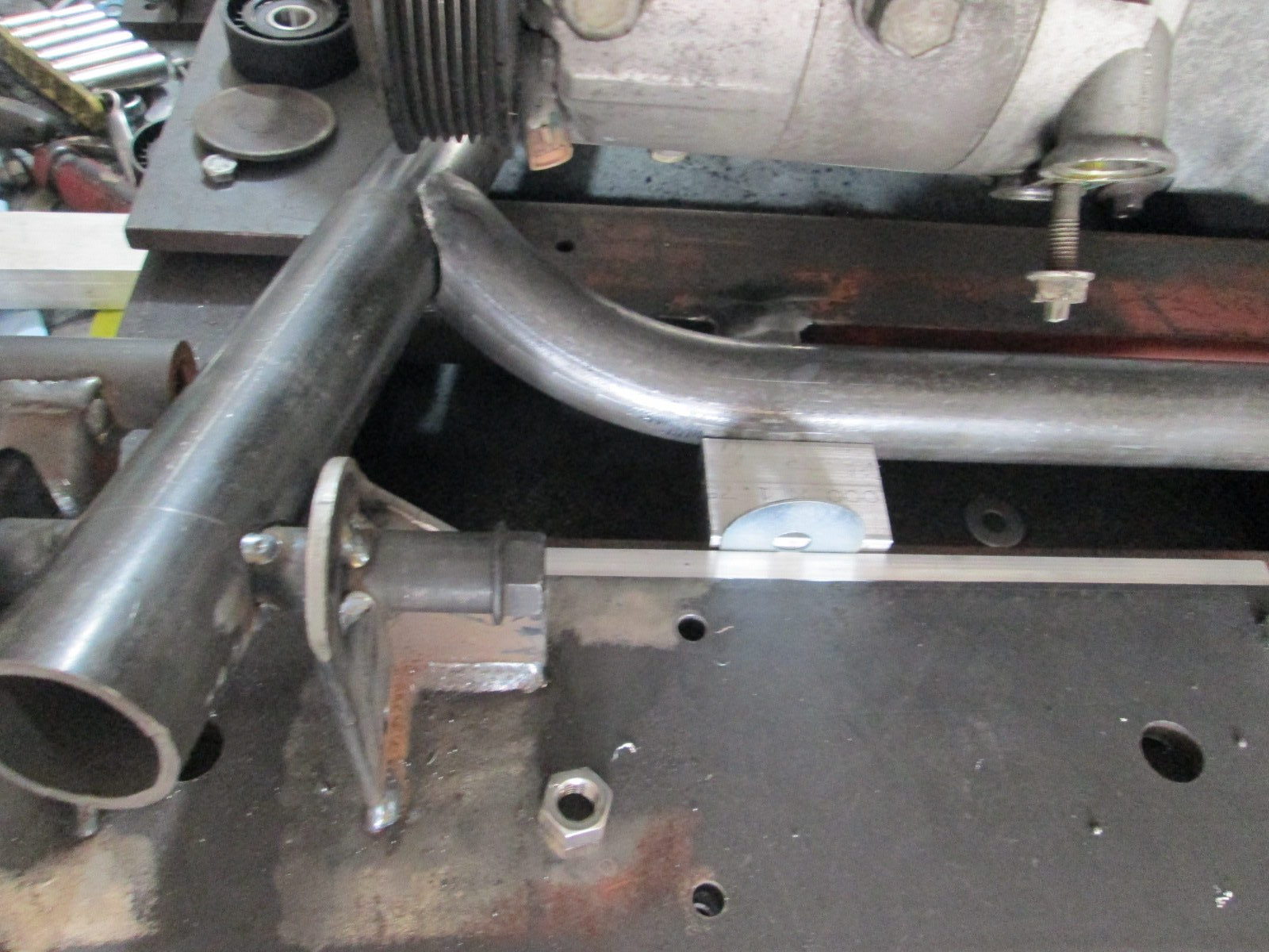
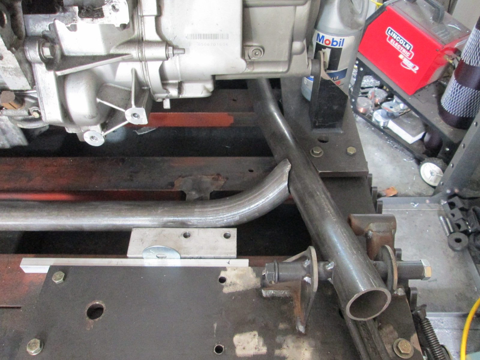
Here is a mock up of the rear crossmember tube. I also positioned the rear suspension pickup plates (proper position front to back, but pulled out about 4" because it won't fit with the drivetrain support plates). You can see the tube will have good alignment with the rear suspension link, but I will likely bend this tube so it will attach further forward and closer to the middle point between the two lateral links. The transmission side will likely be the limiter on how forward I can get the tubes and still clear the differential housing.
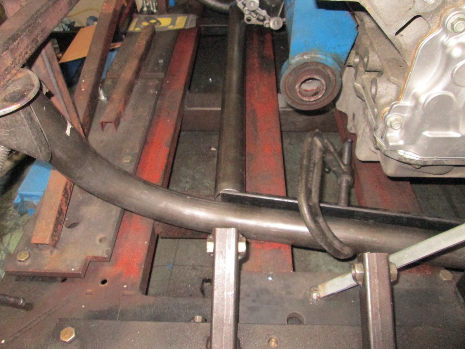
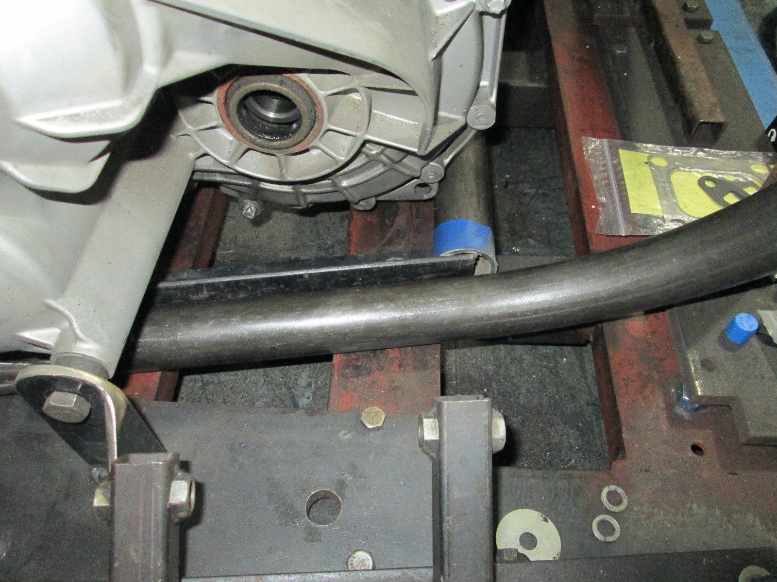
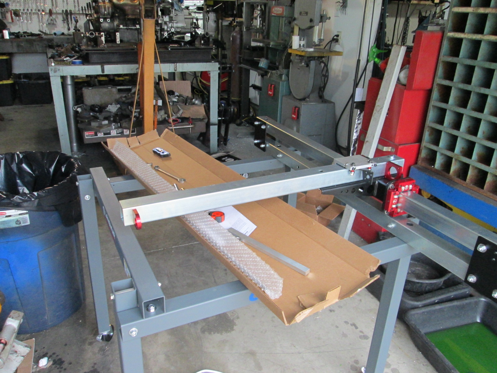
My CNC plasma table arrived this week. Reports are that it takes a few hours to put together, but I think I will continue to focus on the cradle this weekend and work on the table after work next week.
Here is a mock up of the rear crossmember tube. I also positioned the rear suspension pickup plates (proper position front to back, but pulled out about 4" because it won't fit with the drivetrain support plates). You can see the tube will have good alignment with the rear suspension link, but I will likely bend this tube so it will attach further forward and closer to the middle point between the two lateral links. The transmission side will likely be the limiter on how forward I can get the tubes and still clear the differential housing.
My CNC plasma table arrived this week. Reports are that it takes a few hours to put together, but I think I will continue to focus on the cradle this weekend and work on the table after work next week.

 06-13-2020, 06:12 PM
#343
I am hoping the turbo gets me 550 to 600 rwhp at about 8-10 psi with quick spooling for the manual transmission. I am installing the flex fuel sender and would like to keep it non-intercooled for startup. I don't think I will push it much past that as the fuel system, clutch and transmission requirements/costs still start to skyrocket and reduce the ability to daily drive this car 9 months of the year.
Made some more progress today...
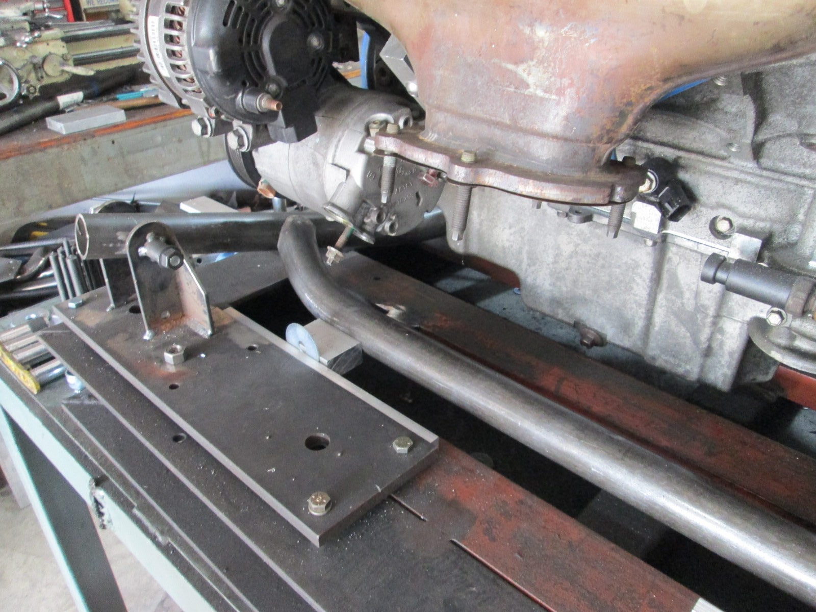
Tacked in the front cradle mount sleeves to help hold the main rails in position:
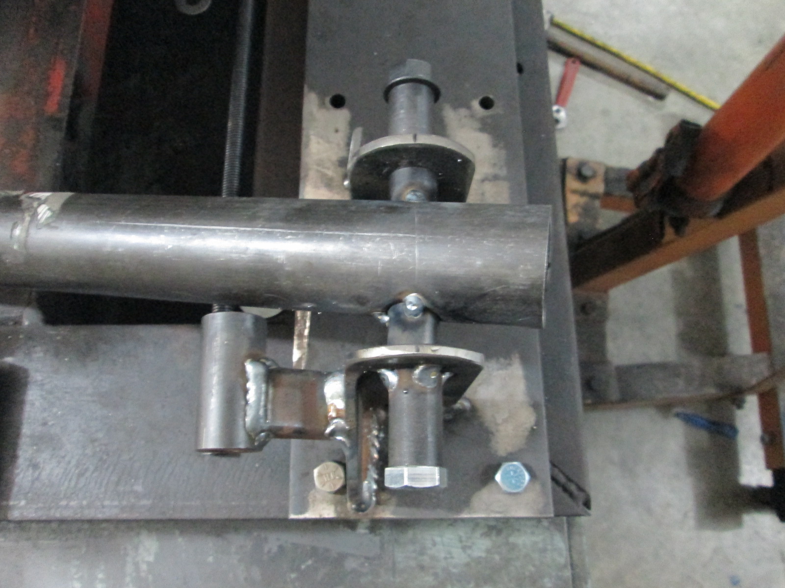
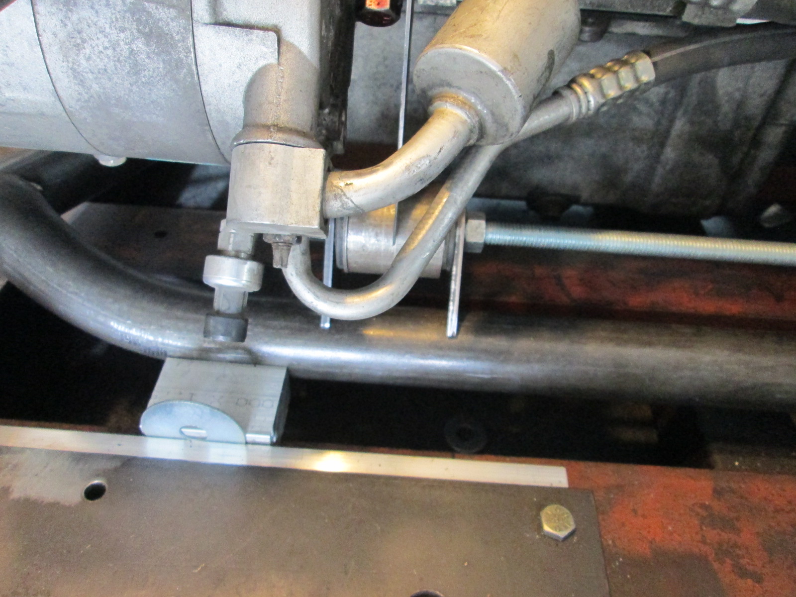
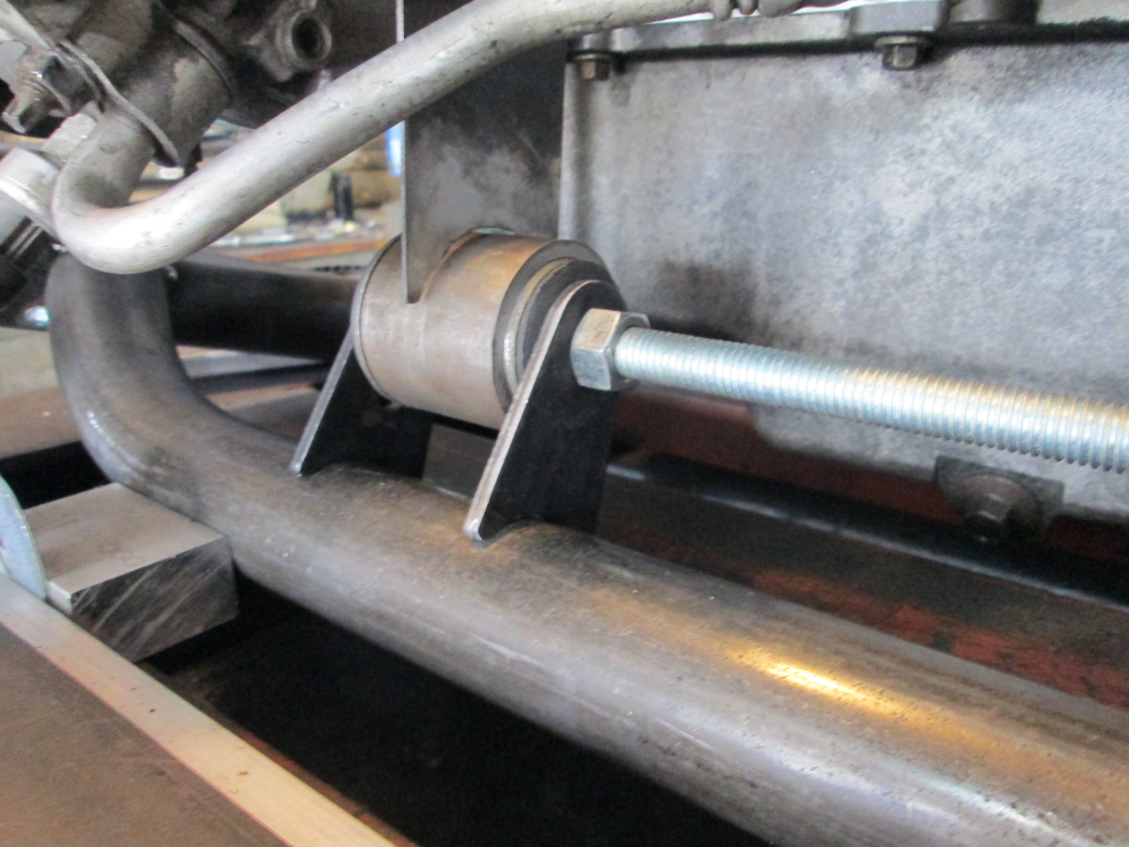
I tacked the rear cradle mounts to the main tubes, bent and shaped the rear crossmember, tacked it in place and clamped it down to keep the cradle in position.
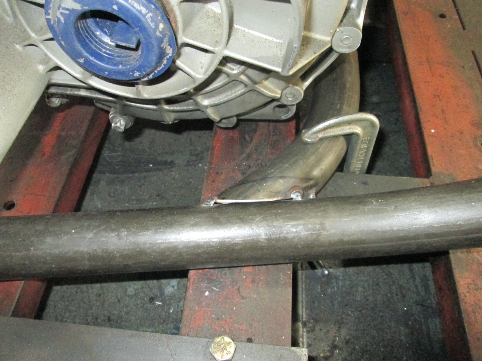
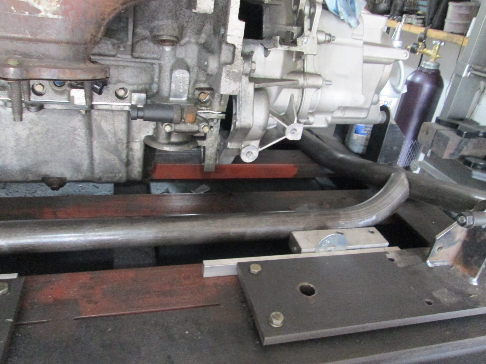
Then removed the rear cradle location fixture so I could install the turbo and check for sway bar clearance.
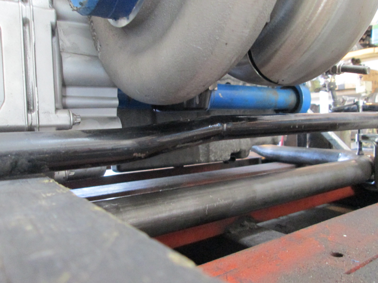
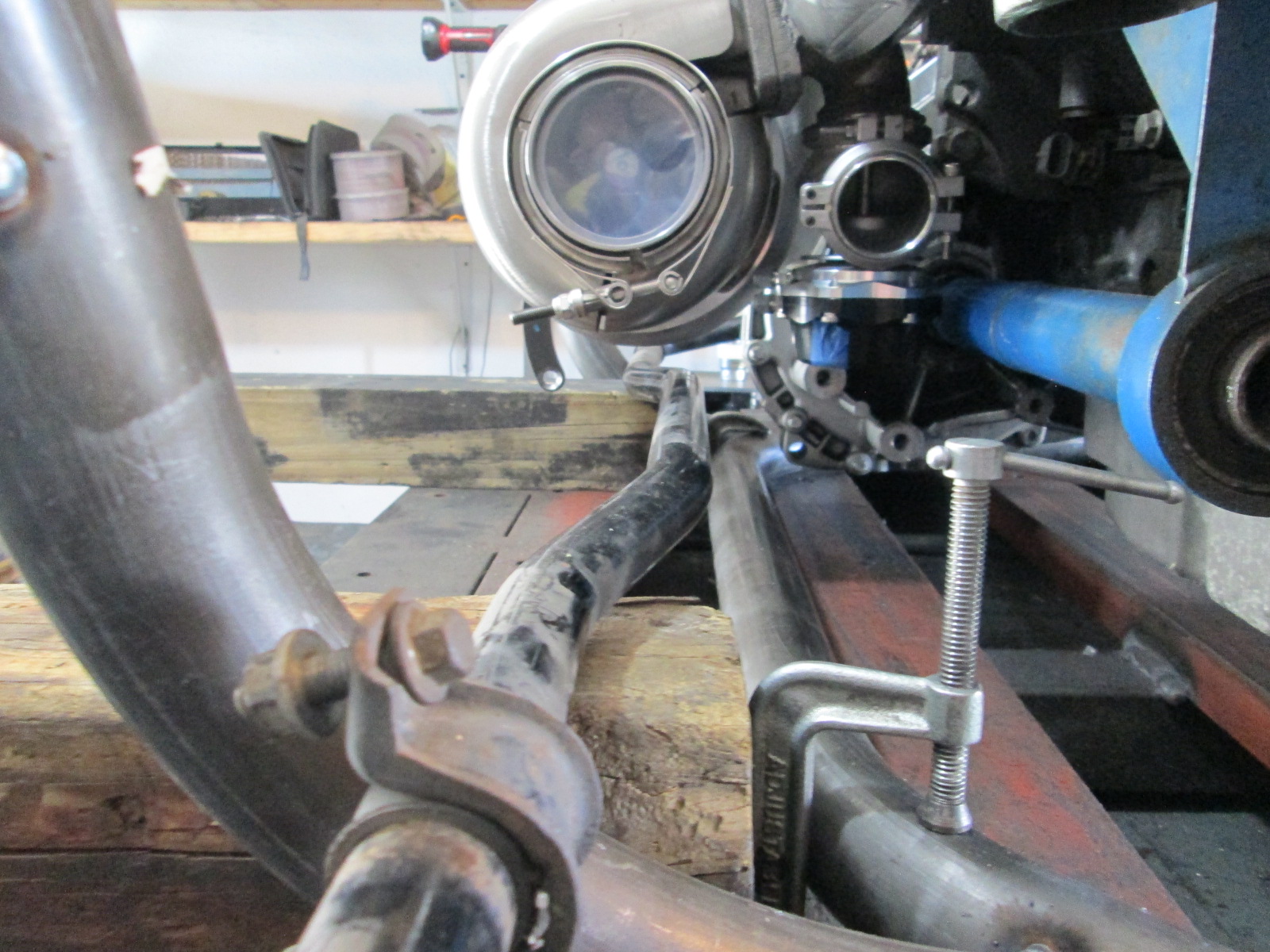
The scribe on the I beam fixture is the stock sway bar mounting surface/position (front to back).
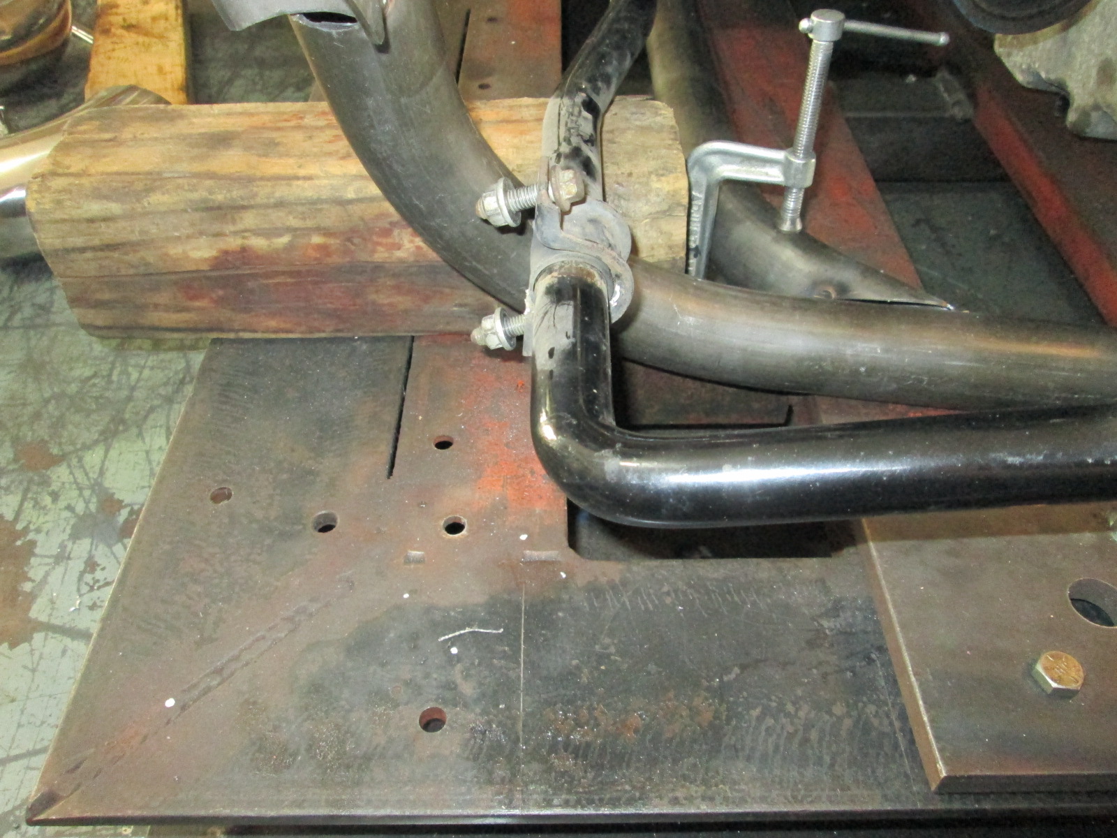
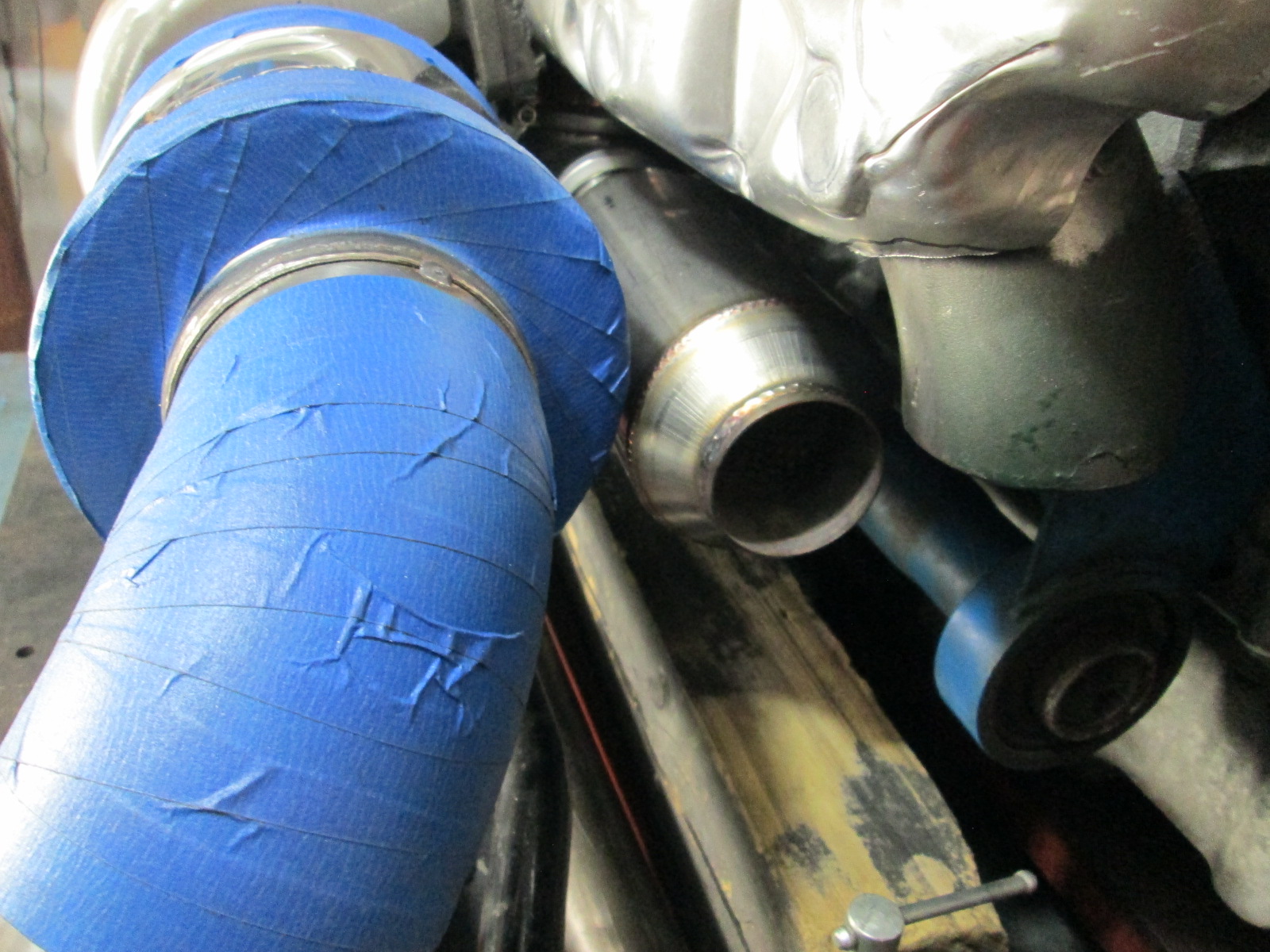
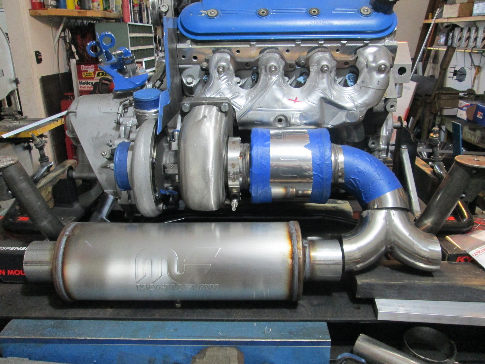
Then I mocked up some of the exhaust bends for measurement and fun. Looks like I have about 7.5" for a 3.5" muffler between the turbo and the exhaust bend so the magnaflow 14160 with a 6" body will fit. Ideally I want to run two mufflers to help keep the car quieter (not that a 3" perforated tube exhaust will ever be quiet...). The 3.5" muffler will also help take the edge off when I run with the 3" cutout open (un-muffled exhaust isn't for me). The 3.5" muffler won't leave room for the wastegate exhaust to joint back up before the 3/5" muffler, so I have sourced a 2" stainless perforated tube muffler for it. With the wastegate having its own muffler, I will have the option to merge it after the 3.5 muffler or just vent it to atmosphere.
 06-14-2020, 06:11 PM
#345
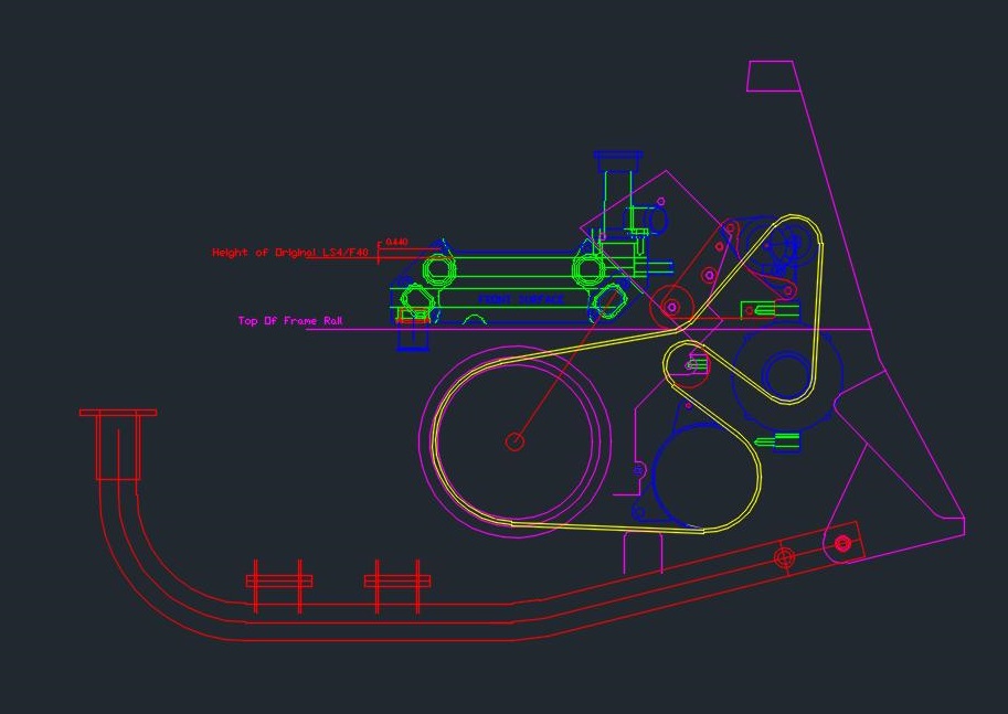
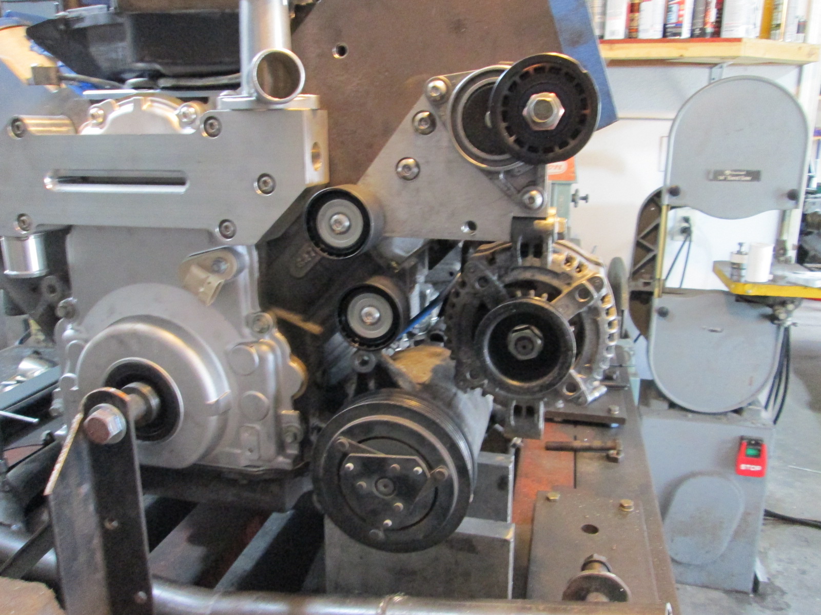
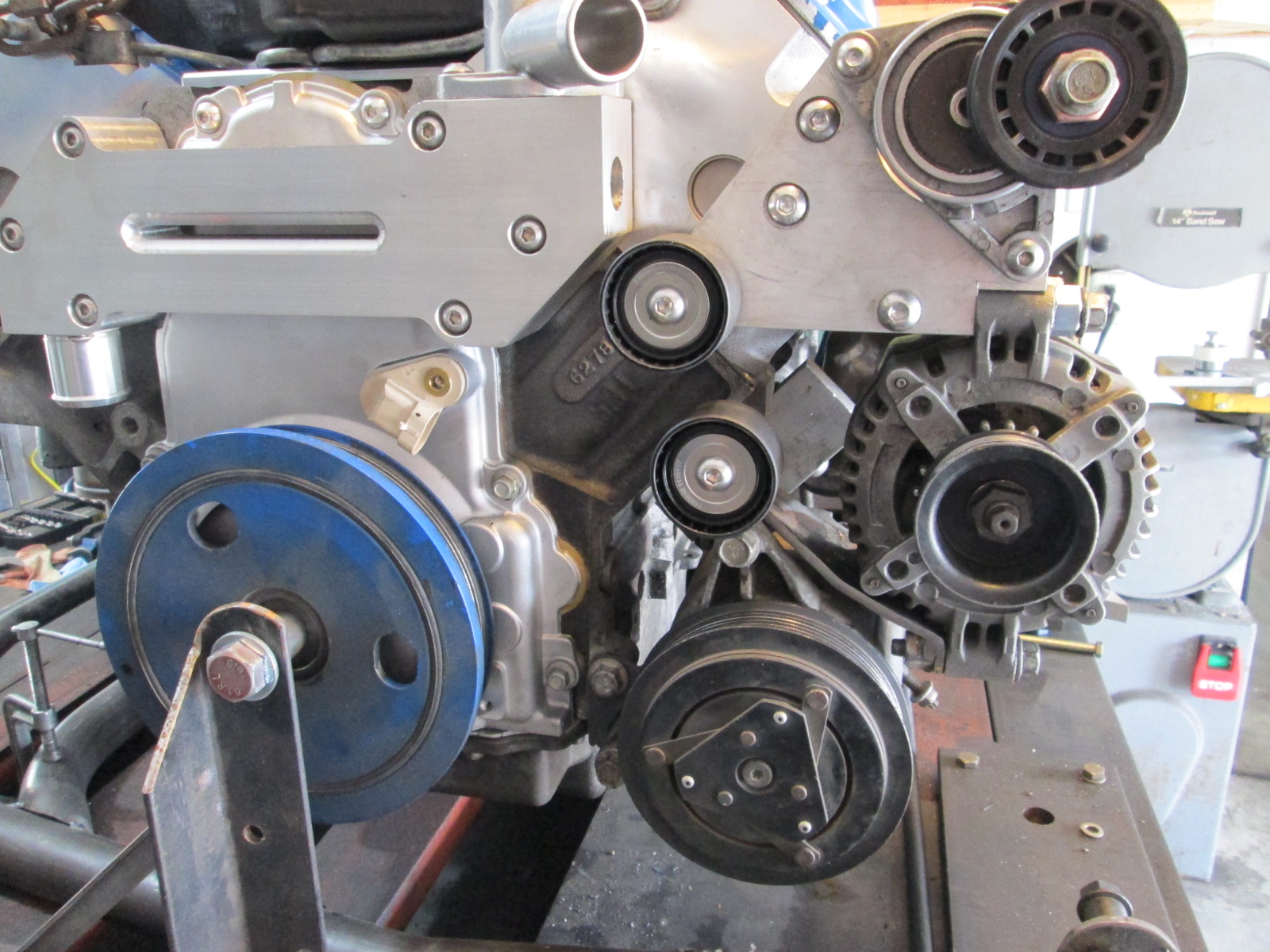
Before I can locate the front crossmember on the cradle, I really needed to nail down the accessory drive. I am going to go electric for now with a pump mounted up front, so that allowed me to raise the alternator and ac position slightly. It was really handing having the chassis with the mock-up engine in the exact same position as the engine on the cradle. I made an adjustable alternator holder, adjusted it in the chassis to the proper location, then I could mount it on the fixture, take some measurements and draw everything up in autoCAD.
New alternator and AC positions:
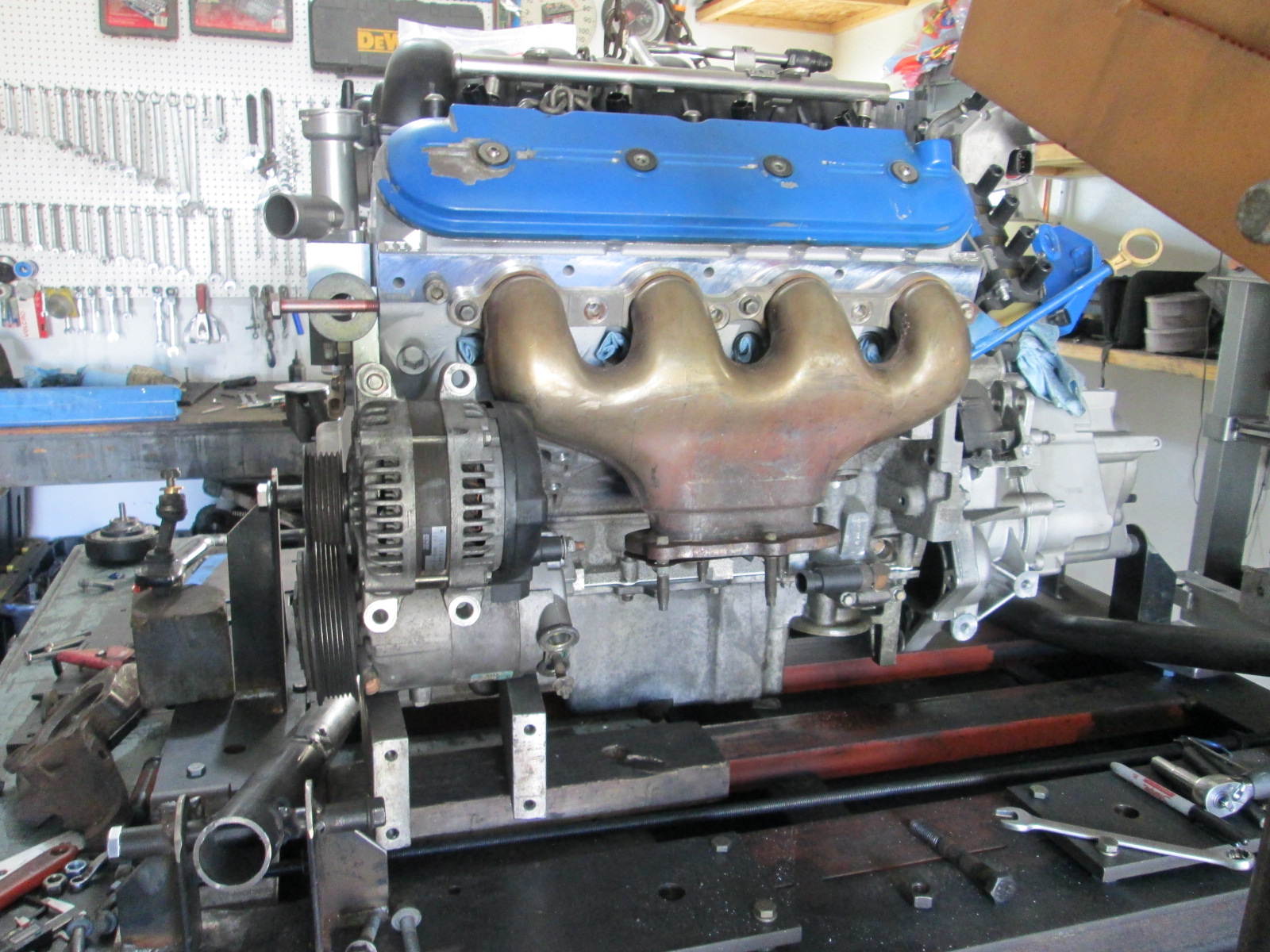
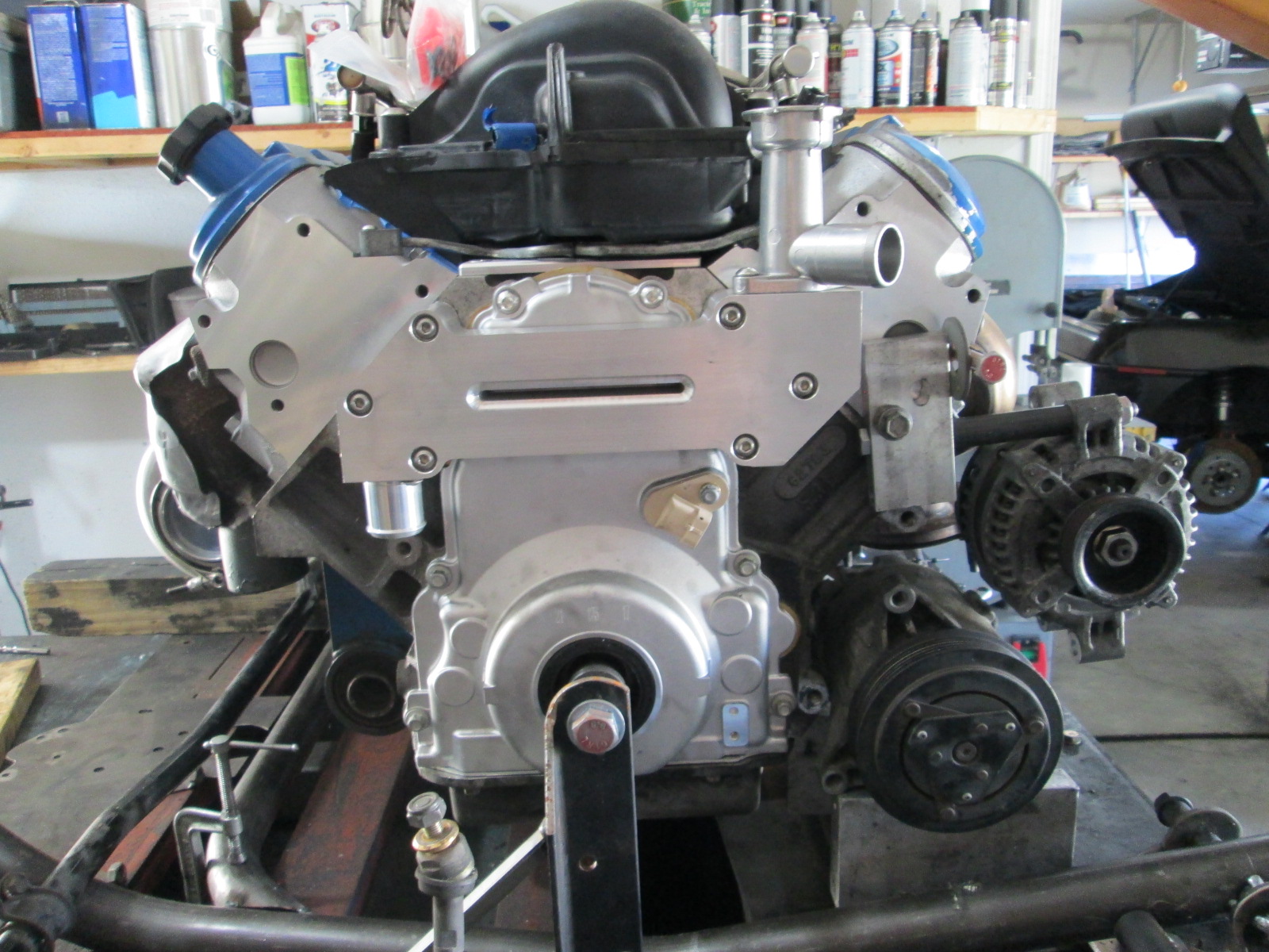
I am glad I decided to install the water manifold/thermostat housing... The Dorman LS2 intake interferes with the nipple boss on the water neck. Also, the steam vent line was in the way as well, so I bent it out of the way for now. So this is another area I will have have to revisit and come up with some additional space.
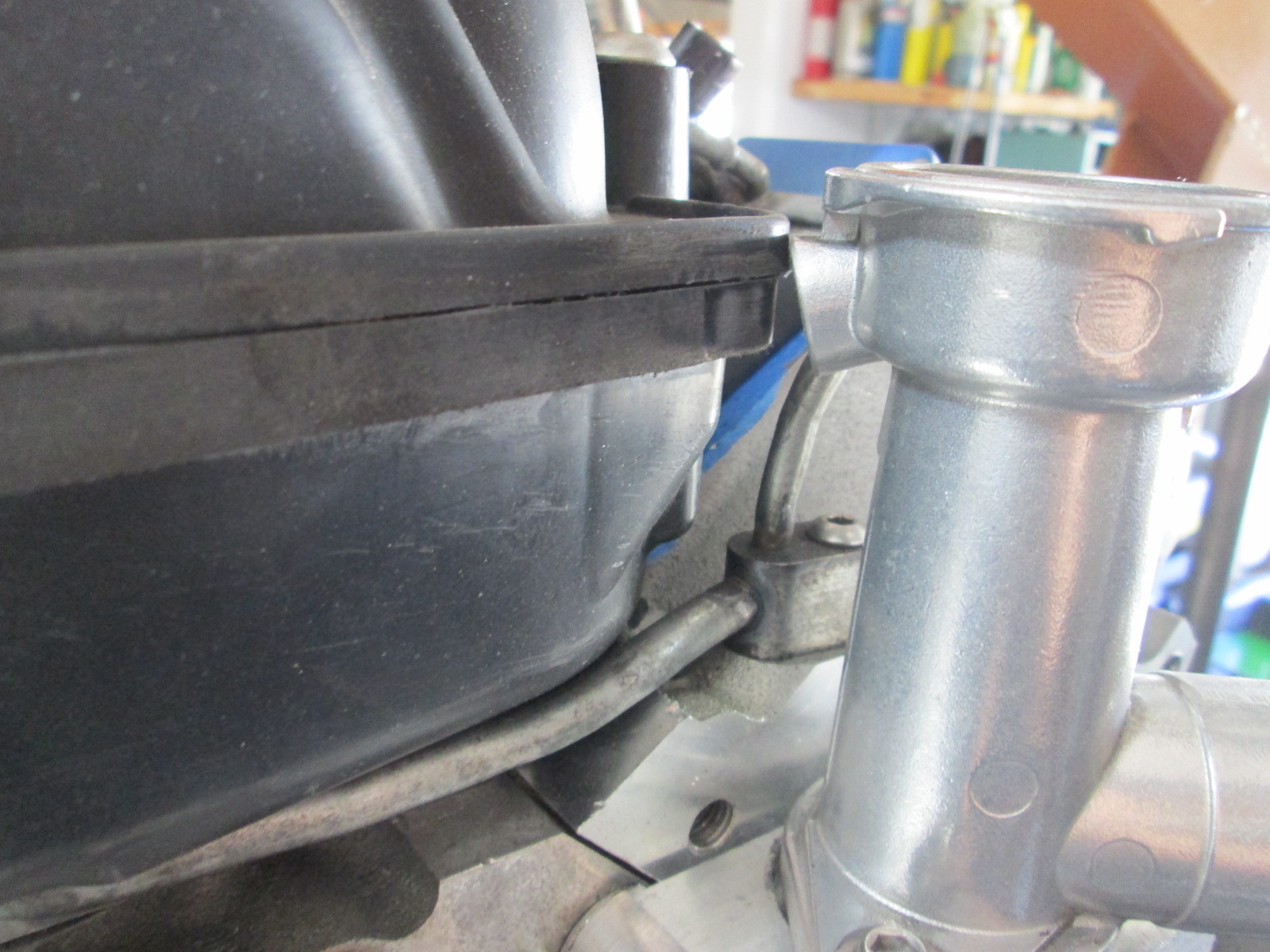
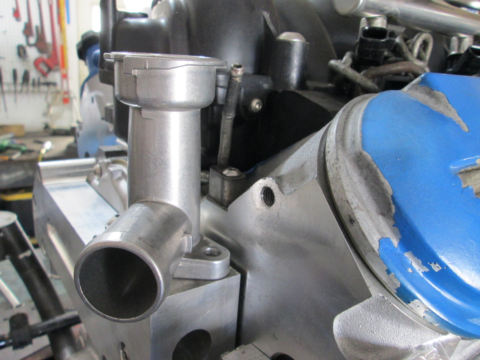
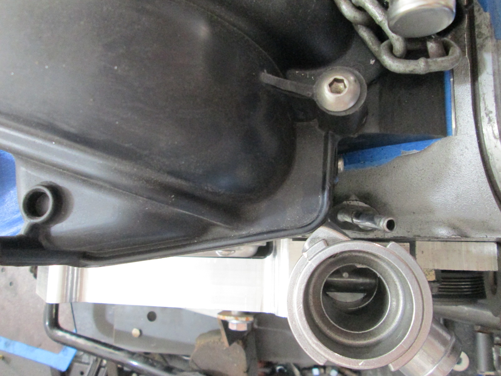
Pretty happy with the progress this weekend. I also ordered the 3.5" x 6 magnaflow muffler, the muffler for the waste gate, some aluminum plate for the new alternator bracket (all drawn up in autoCAD), and the two idler pulleys that will allow me to reuse stock bolt locations on the engine.
New alternator and AC positions:
I am glad I decided to install the water manifold/thermostat housing... The Dorman LS2 intake interferes with the nipple boss on the water neck. Also, the steam vent line was in the way as well, so I bent it out of the way for now. So this is another area I will have have to revisit and come up with some additional space.
Pretty happy with the progress this weekend. I also ordered the 3.5" x 6 magnaflow muffler, the muffler for the waste gate, some aluminum plate for the new alternator bracket (all drawn up in autoCAD), and the two idler pulleys that will allow me to reuse stock bolt locations on the engine.
The following users liked this post:
Project GatTagO (06-14-2020)
06-15-2020, 04:51 AM
#346

On the coolant neck where it hits the doorman intake, Can�t you merely cut it li the middle of the riser ( the skinny long section) and clock it to gain your clearance needed and weld it?
06-15-2020, 04:51 AM
#347
On the coolant neck where it hits the doorman intake, Can�t you merely cut it li the middle of the riser ( the skinny long section) and clock it to gain your clearance needed and weld it?
06-15-2020, 03:24 PM
#348
Launching!

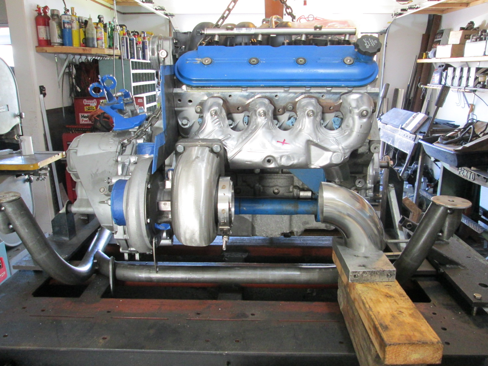
That turbo looks fairly large physically mounted up next to the block - at least in the photo.
Is a rad cap gonna clear that intake manifold as well? looks like it could be close there.
Is a rad cap gonna clear that intake manifold as well? looks like it could be close there.
06-15-2020, 07:32 PM
#349
Good catch on the cap. I need to check that too!
 07-19-2020, 04:44 PM
#351
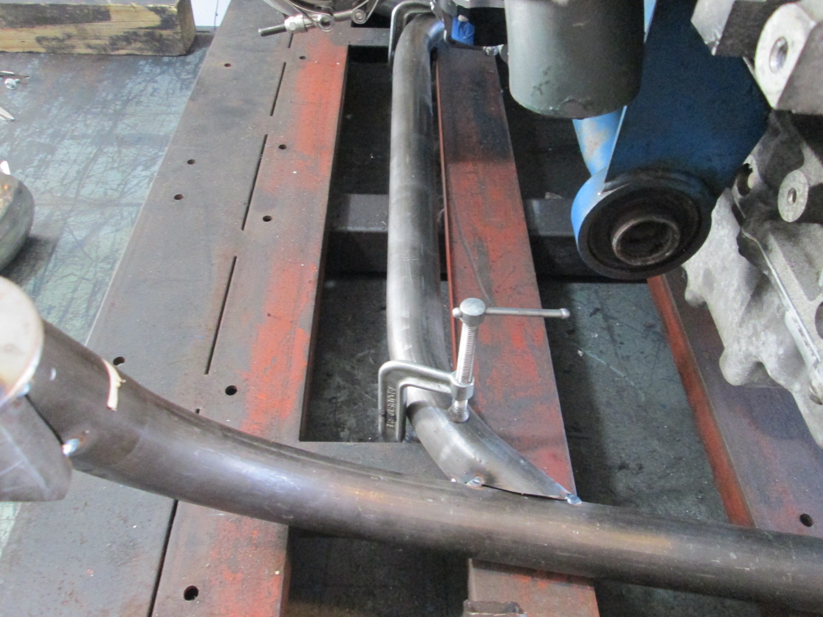
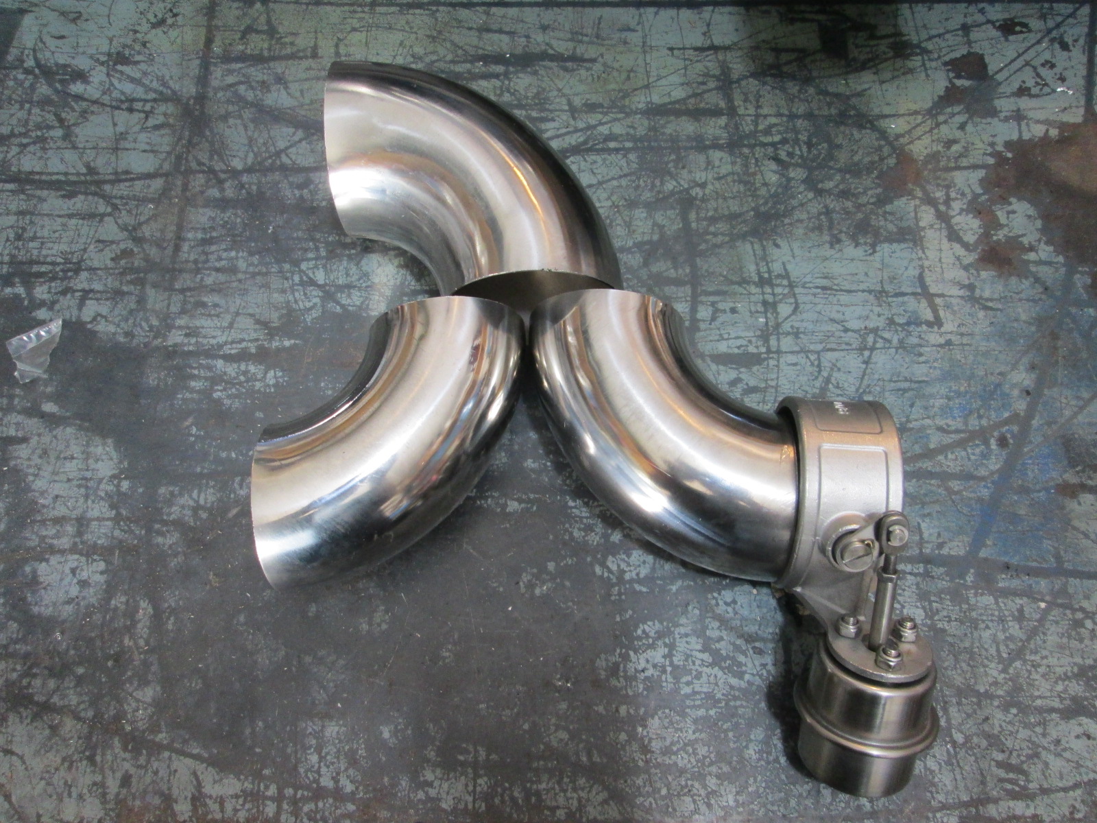
Been super busy with work, but still slowly plugging away at the swap. Was able to mock up the exhaust a little more:
Did get the plasma table assembled, made a test part program and checked its motion. Maybe in the next week or two I will have some test cuts done.
Did get the plasma table assembled, made a test part program and checked its motion. Maybe in the next week or two I will have some test cuts done.
The following users liked this post:
JoshHefnerX (07-20-2020)
07-21-2020, 07:54 AM
#355
Do you think you might be entering into territory where some sort of positive engine bay air circulation/venting is needed? Just thinking of past ownership of an MR2 and a Cayman S -- both had engine bay vent fans that came on when certain temps were reached. And neither of those were sporting turbos....just an errant thought. Love the craftsmanship!
Edit - and perhaps the Fiero was so equipped....
Edit - and perhaps the Fiero was so equipped....
 07-21-2020, 07:41 PM
#357
The 85-87 V6 cars did have a little blower fan the blew air on the coil and alternator when the radiator fan kicked on, but it was discontinued with the 88s and improved electronics.
With all the planned hotness on the rear side of the engine, all accessories and all movable wiring is moved to the front side away from the heat as much as possible. There are engine bay vents at the front corners of the engine decklid, but no current vents at the rear, but I could definitely add one if needed. The rear is up against a trunk wall with an upper ledge, which will have a layer of metal heat shielding, plus the turbine and mufflers will have their own heat shields, which should help contain the majority of the heat to things that are OK to be really hot. There will also be some heat shields to help isolate the compressor side of the turbo and air filter from the muffler area.
When I get it running, I will likely keep the carpet out of the truck while I drive it with and without heat shields and take some temp readings to get a feel for how effective the heat shielding is and determine if I need to add some venting right in front on the rear trunk wall.
07-21-2020, 08:32 PM
#358
It's the "should help contain the majority of the heat....." that I'd be concerned with - I'd rather get rid of it than "contain" it. But, you've clearly thought it through (nice job!) - probably good enough for testing and see what you get. Love the work....
08-30-2020, 01:24 PM
#359
I finally got some time to finish up the alternator and AC brackets. I still need to refine the placement and size of the idler pulleys and tension, but now I can bend up the front cross member and get started on the front engine and transmission mount.
The following 3 users liked this post by fieroguru:
09-07-2020, 05:12 PM
#360
I have had more free time in the past 2 weeks and really trying to make some good progress on the swap.
Front crossmember tube was bent, fitted and tacked into place.
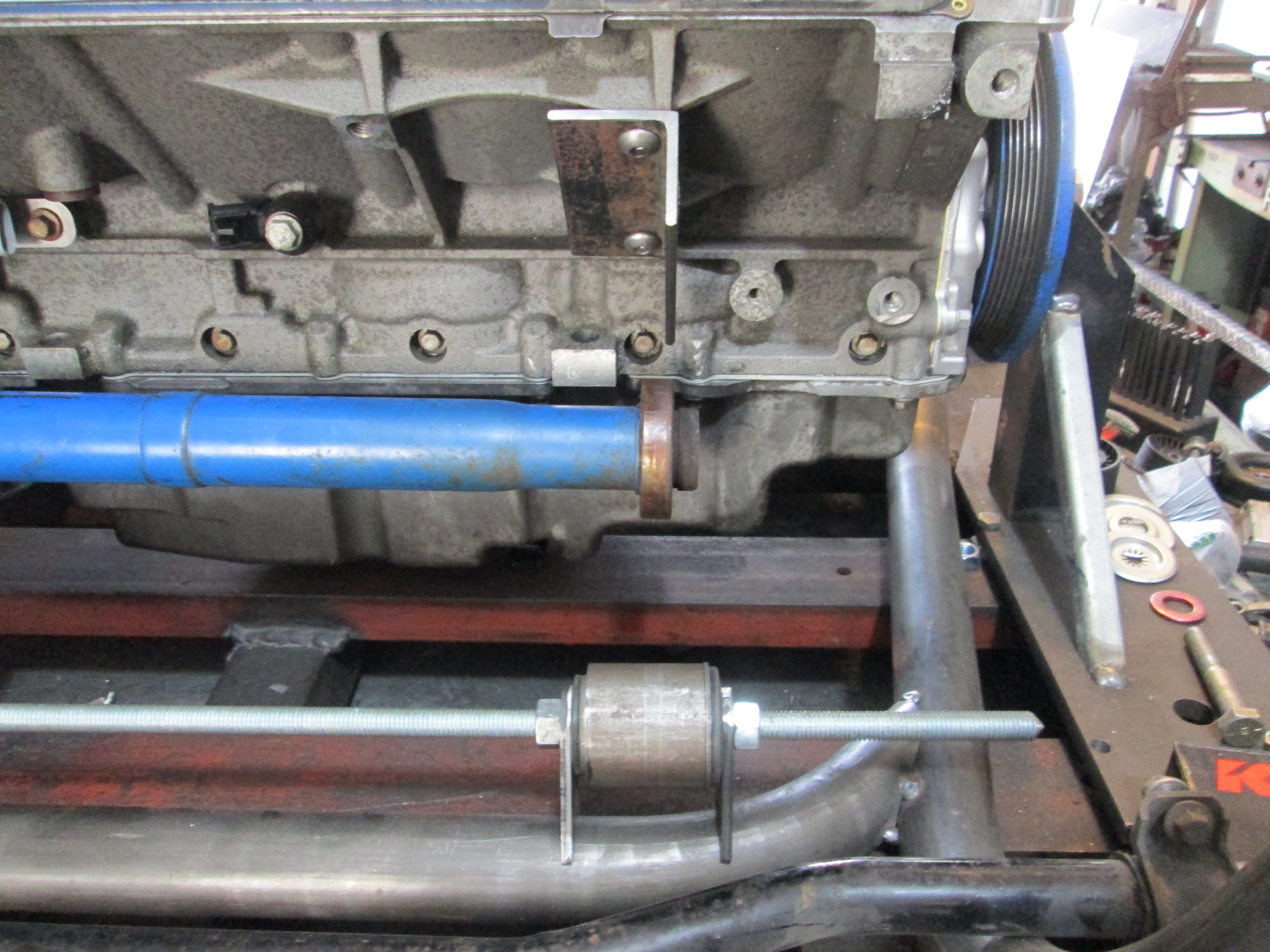
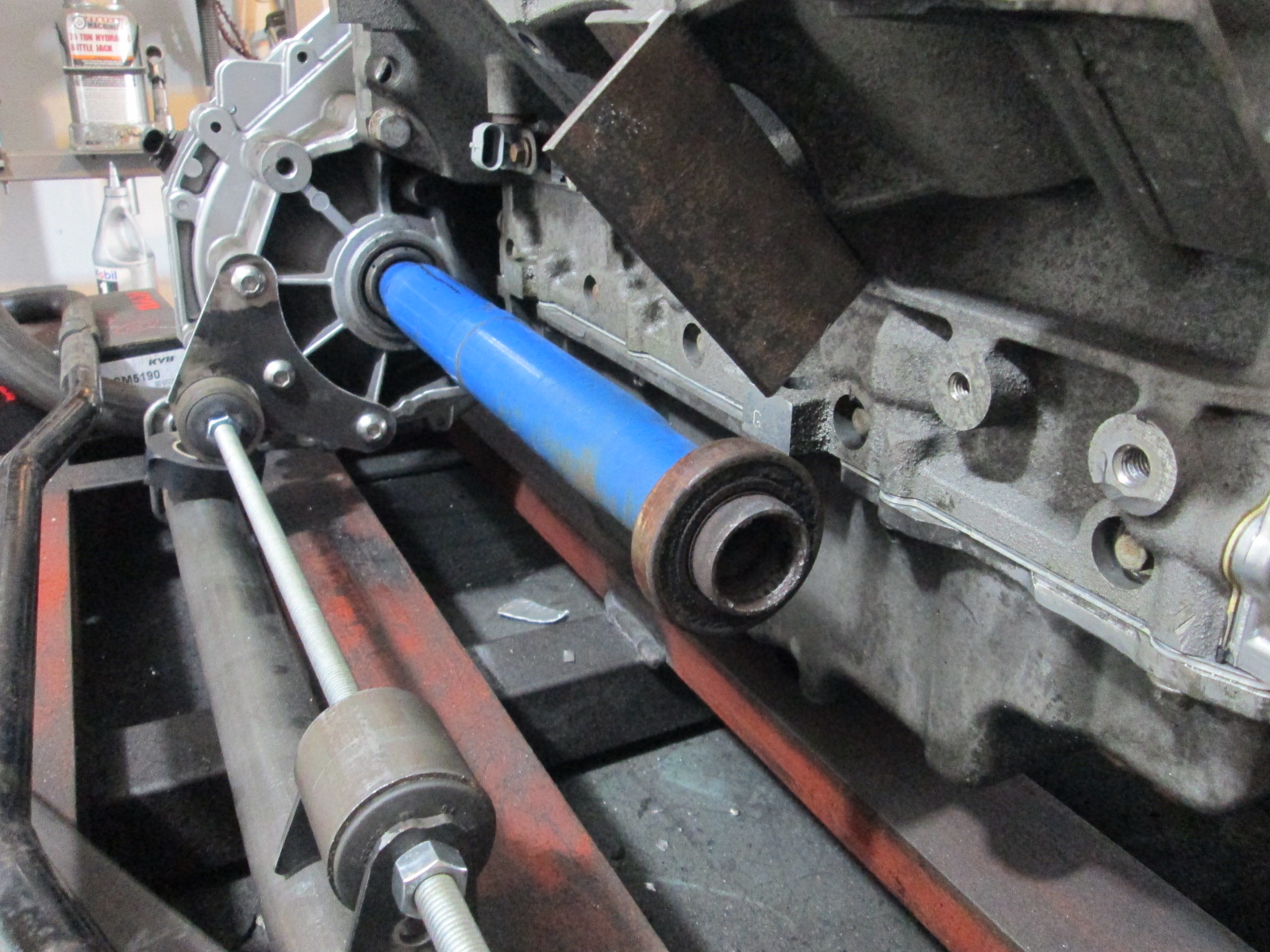
Then I started moving up the engine/transmission mounts. I started with 16ga steel as it is quick to drill, shear, and shape. after all the mounts are mocked up, I will use the 16ga templates to make the final mounts out of 1/8" steel.
Front Transmission:
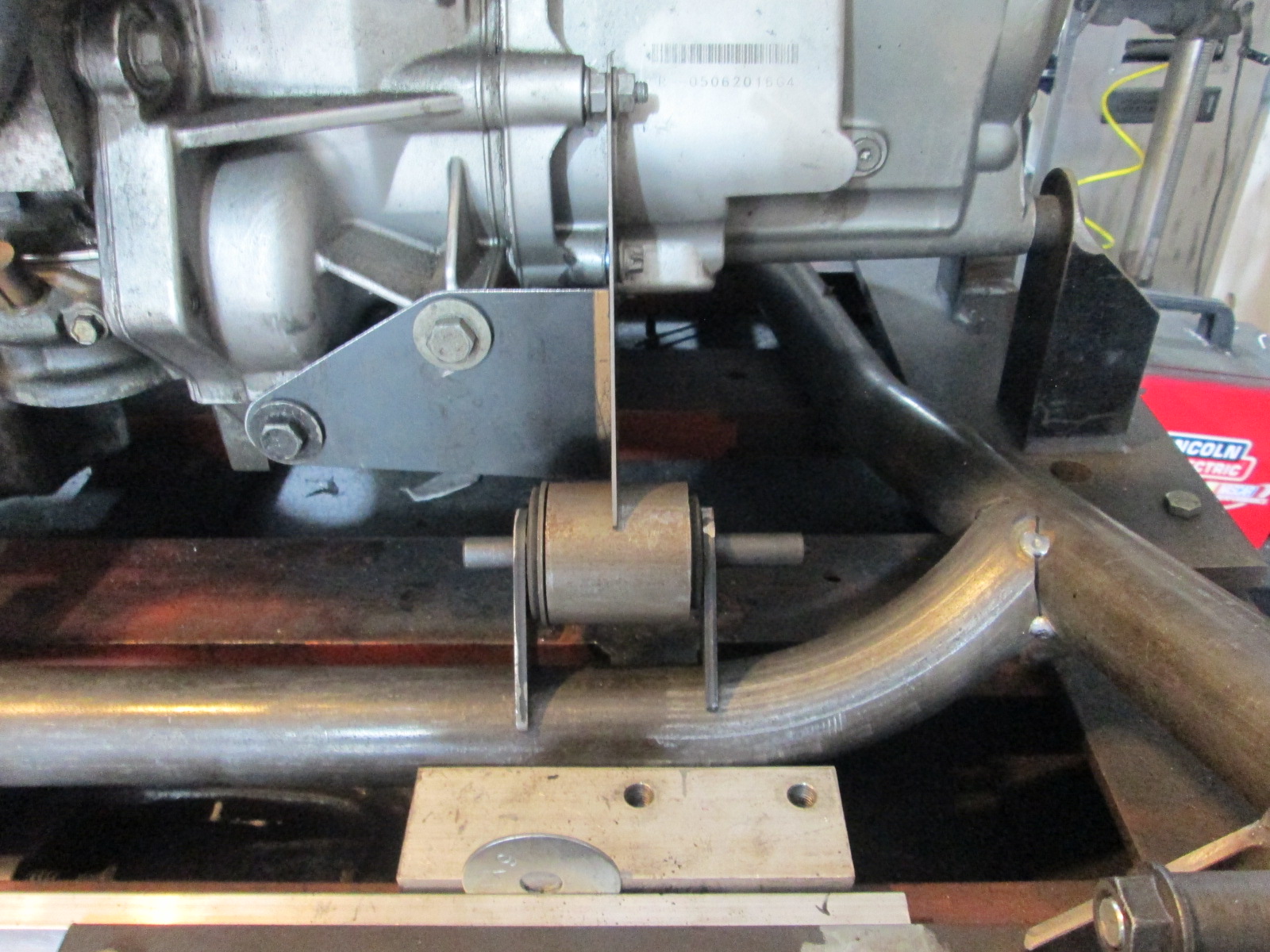
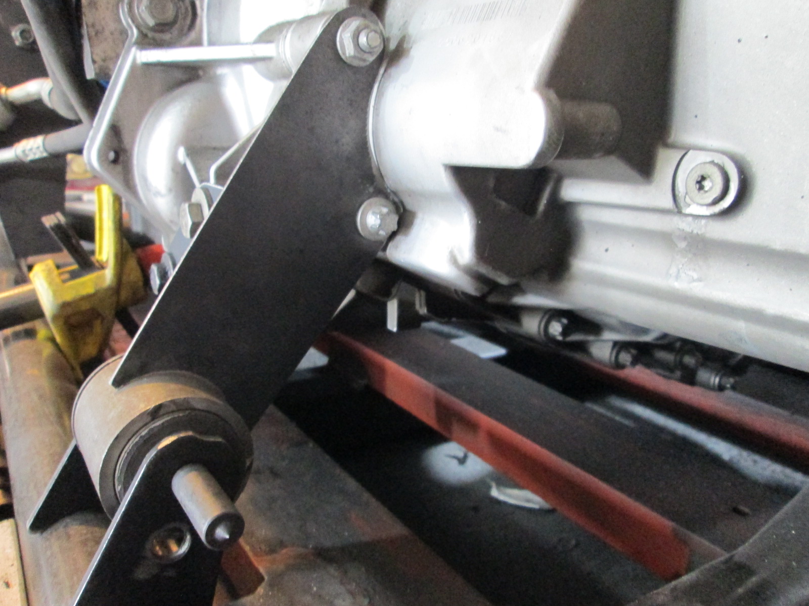
Front Engine:
Rear Transmission:
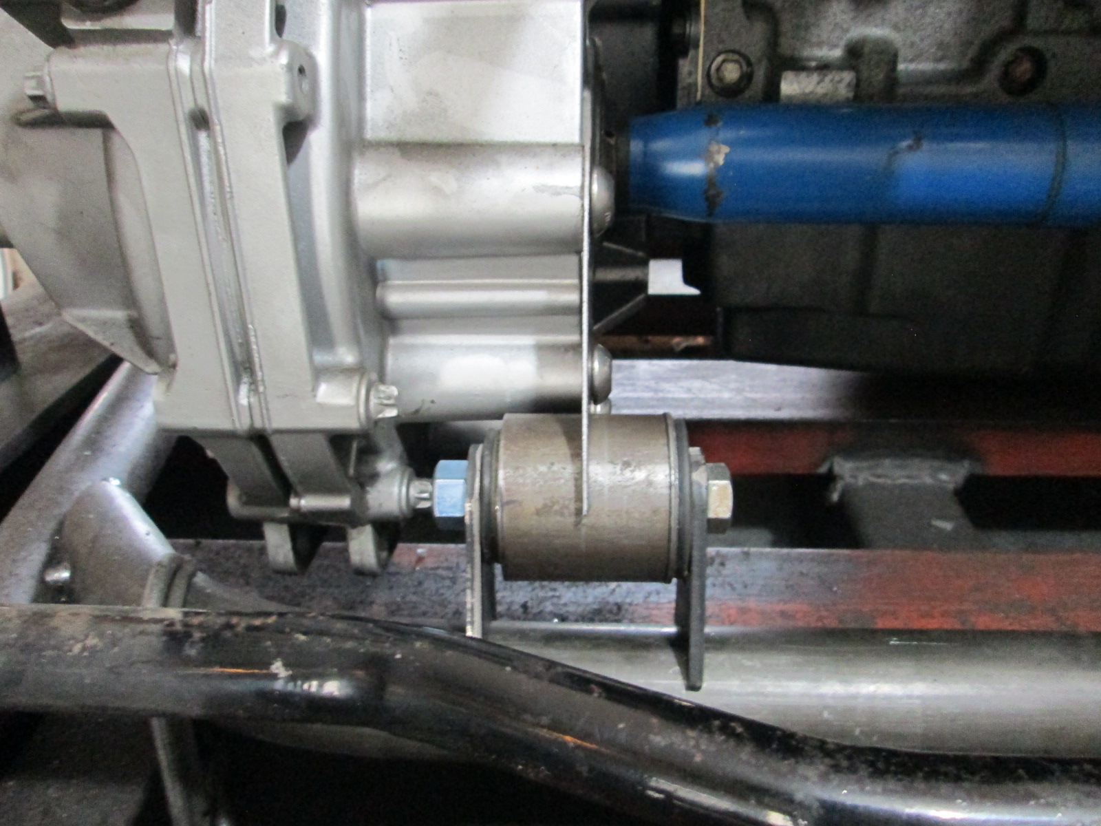
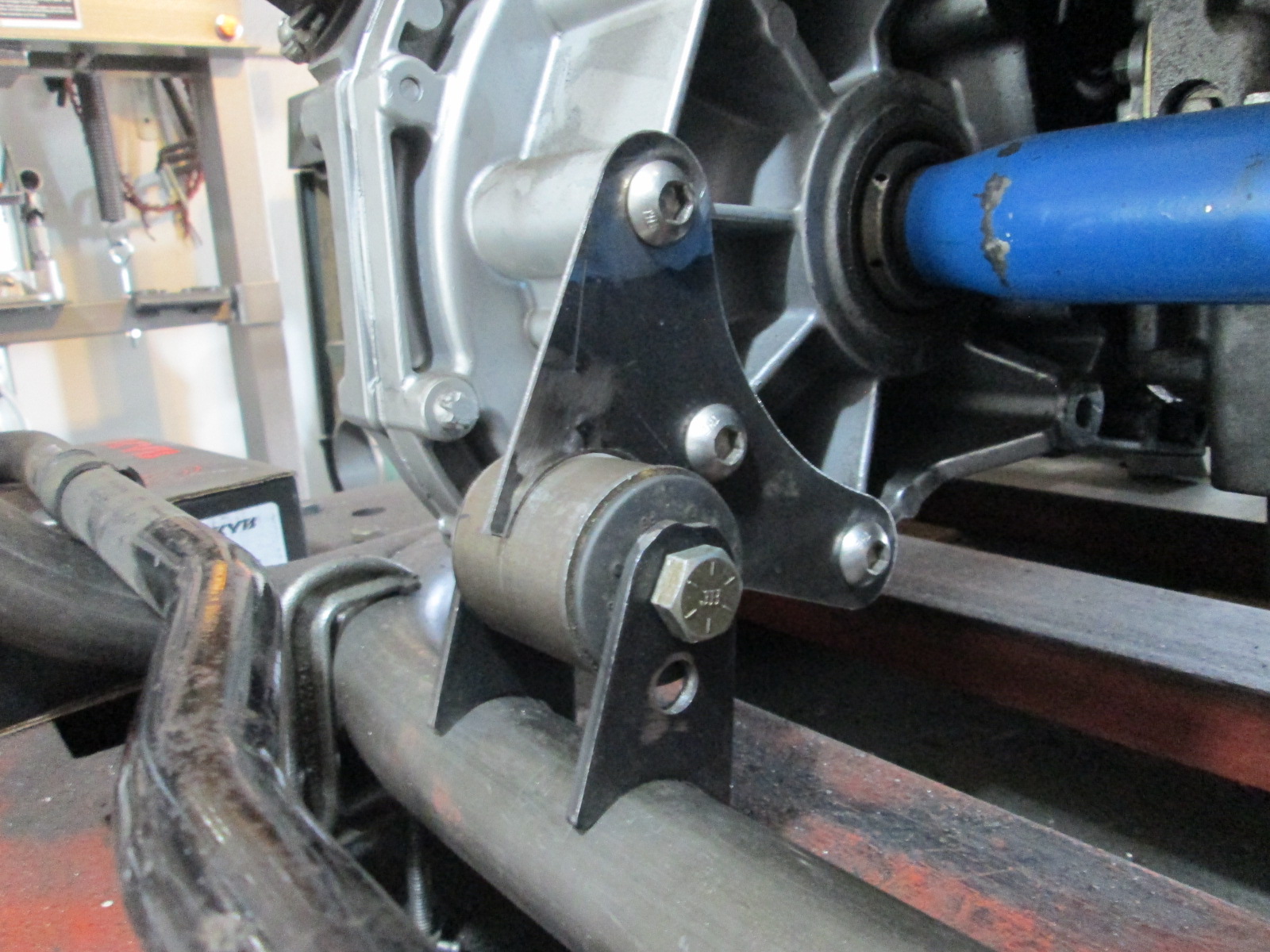
Rear Engine:
Front crossmember tube was bent, fitted and tacked into place.
Then I started moving up the engine/transmission mounts. I started with 16ga steel as it is quick to drill, shear, and shape. after all the mounts are mocked up, I will use the 16ga templates to make the final mounts out of 1/8" steel.
Front Transmission:
Front Engine:
Rear Transmission:
Rear Engine: