
88 Fiero Formula LS4/F40 6 speed swap
 09-13-2020, 06:49 PM
#361


All the mounts are now complete.
The other good news is that the new mounts are 9 lbs 0.7 oz lighter than the original ones.
Front Side:
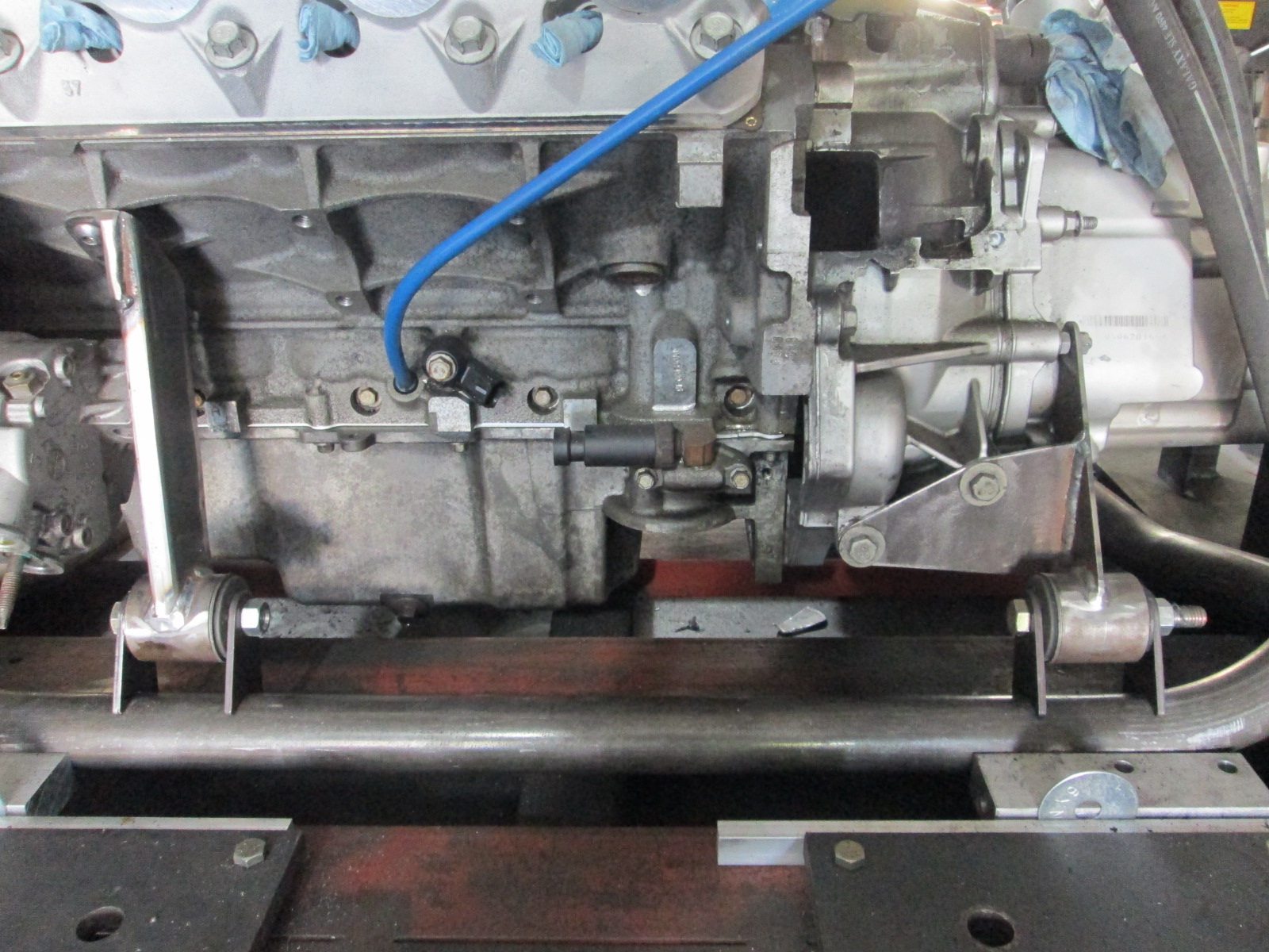
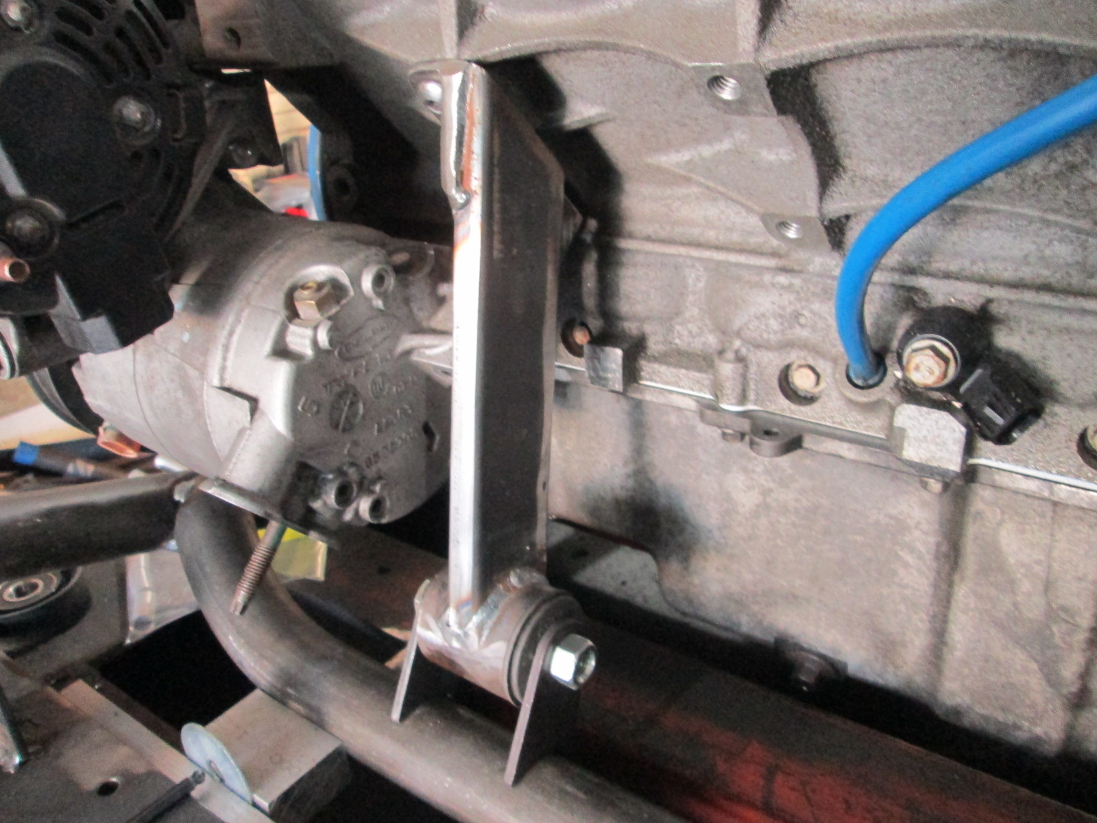
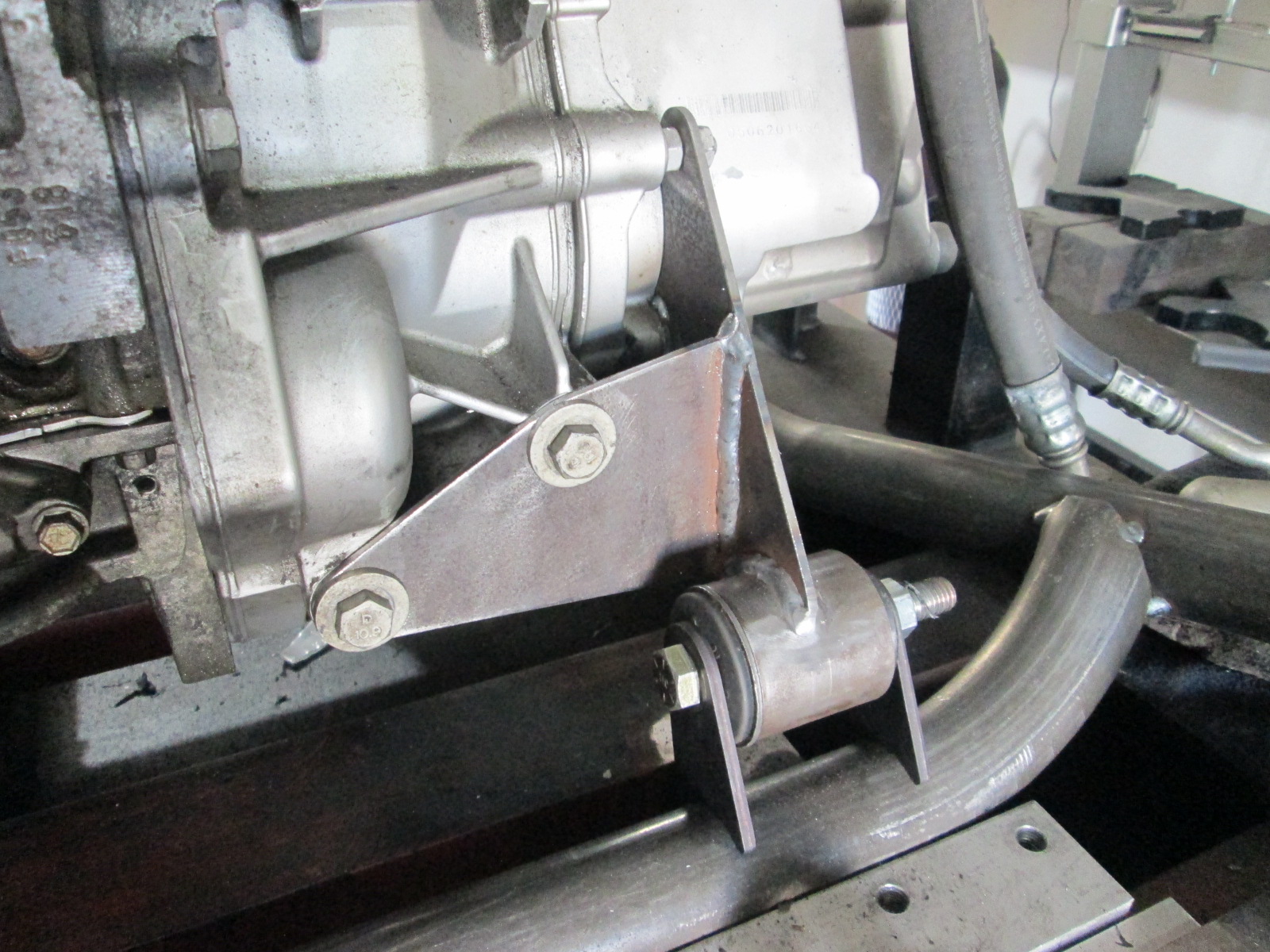
Rear Side:
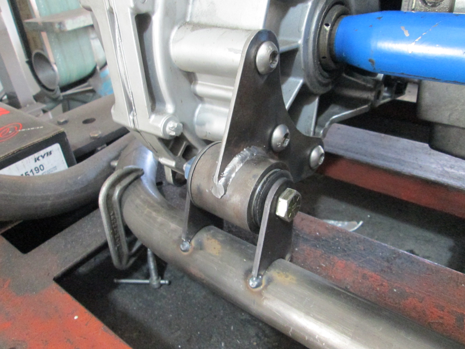
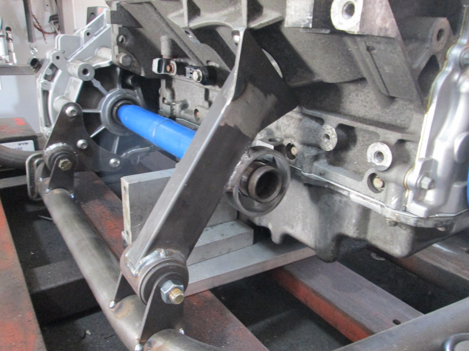
The next step is to finish tacking the bushing tabs to the front crossmember, then do another test fit so I can locate the 3" muffler to ensure it clears the trunk.
The other good news is that the new mounts are 9 lbs 0.7 oz lighter than the original ones.
Front Side:
Rear Side:
The next step is to finish tacking the bushing tabs to the front crossmember, then do another test fit so I can locate the 3" muffler to ensure it clears the trunk.

The following 6 users liked this post by fieroguru:
87mcss (09-15-2020), AAIIIC (09-14-2020), Capt Fiero (09-13-2020), JayinMI (09-16-2020), JoshHefnerX (09-13-2020), and 1 others liked this post.
09-19-2020, 05:35 PM
#363
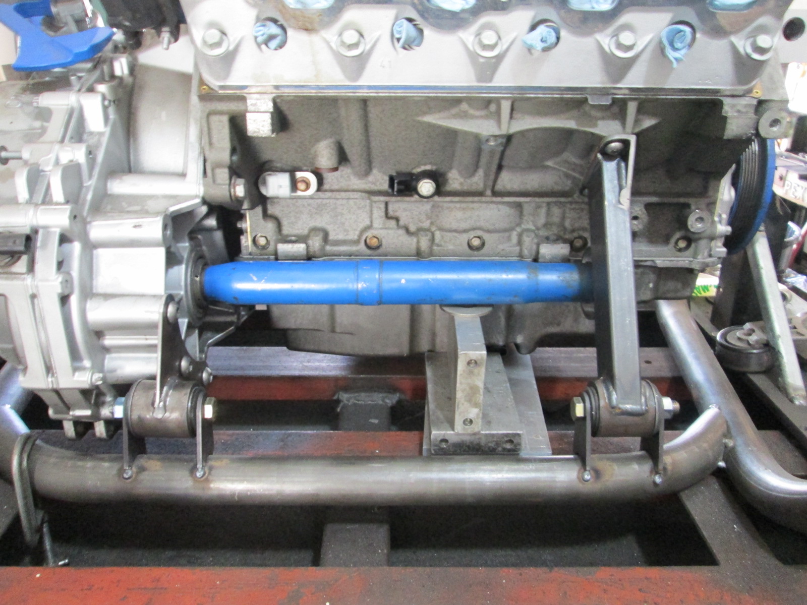
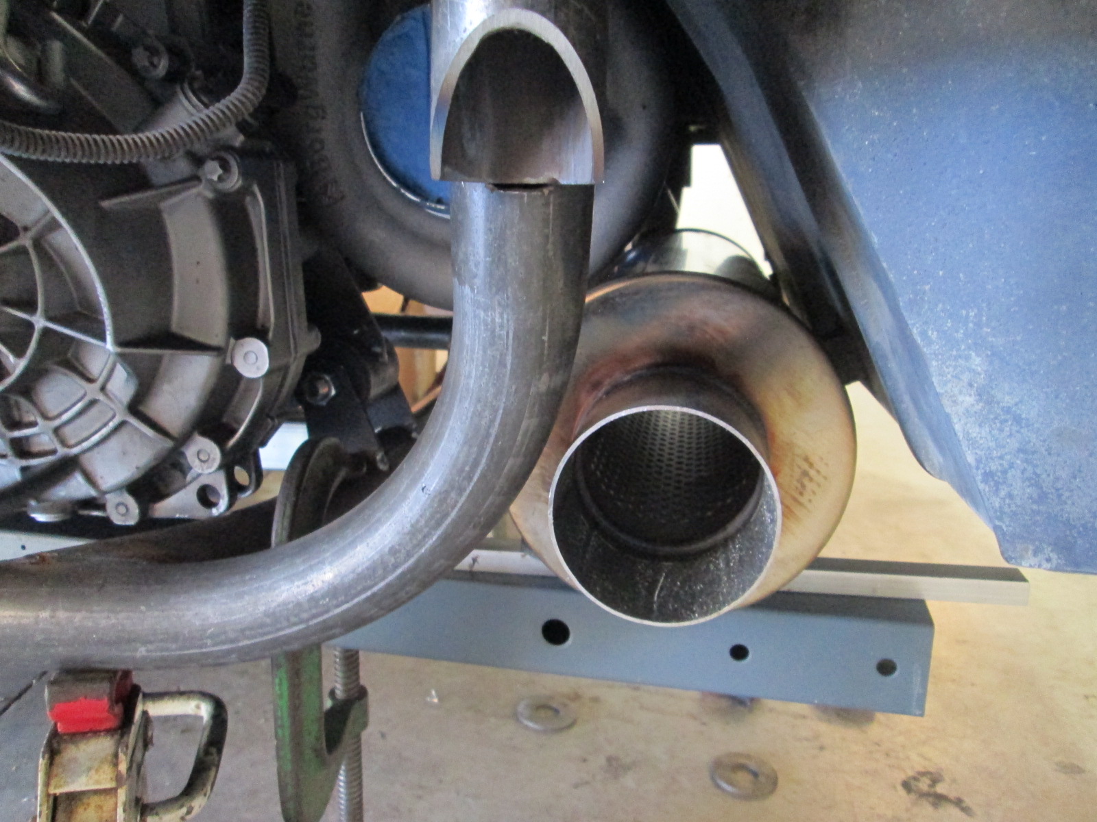
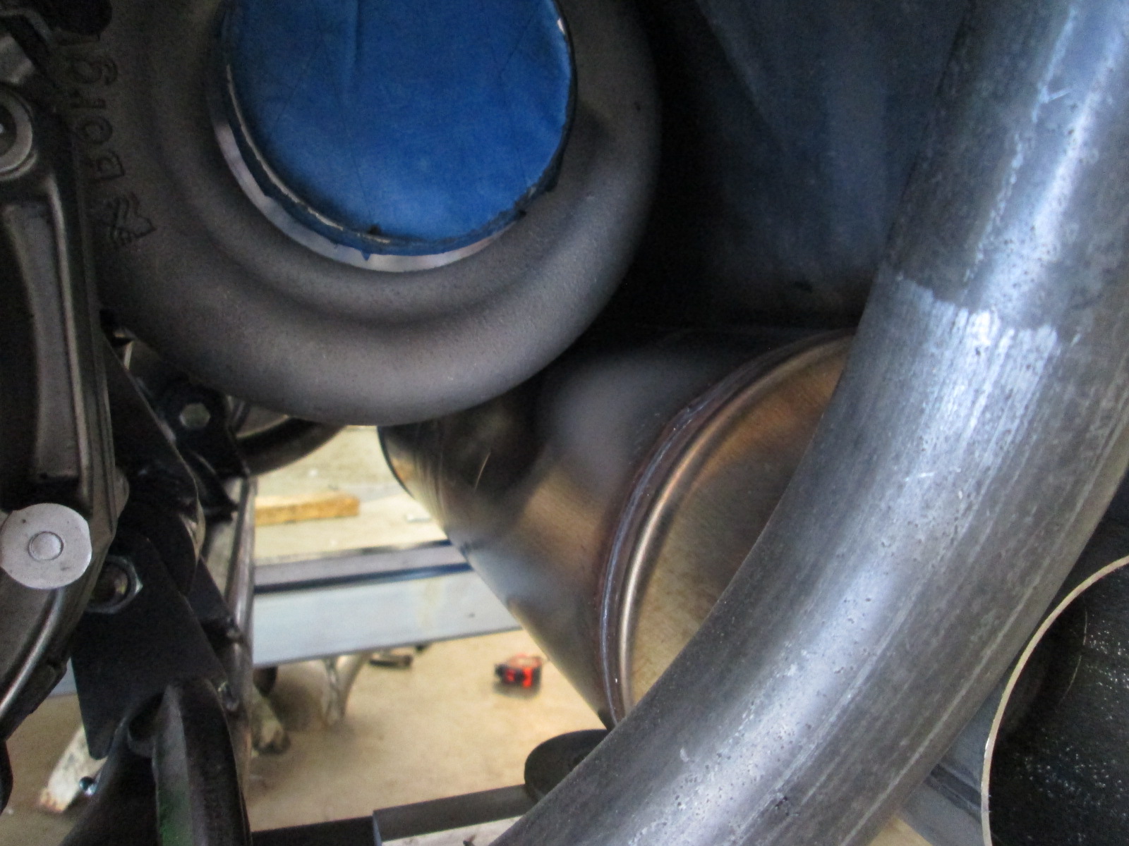
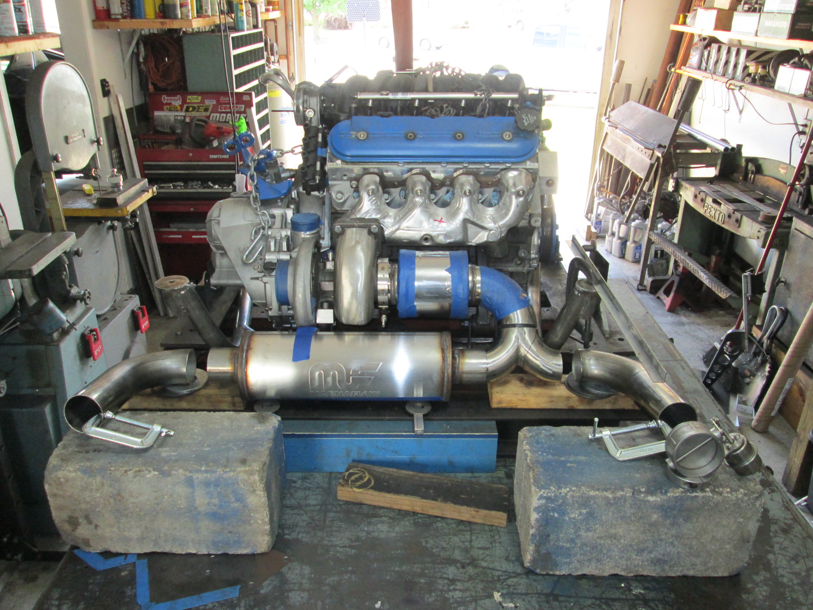
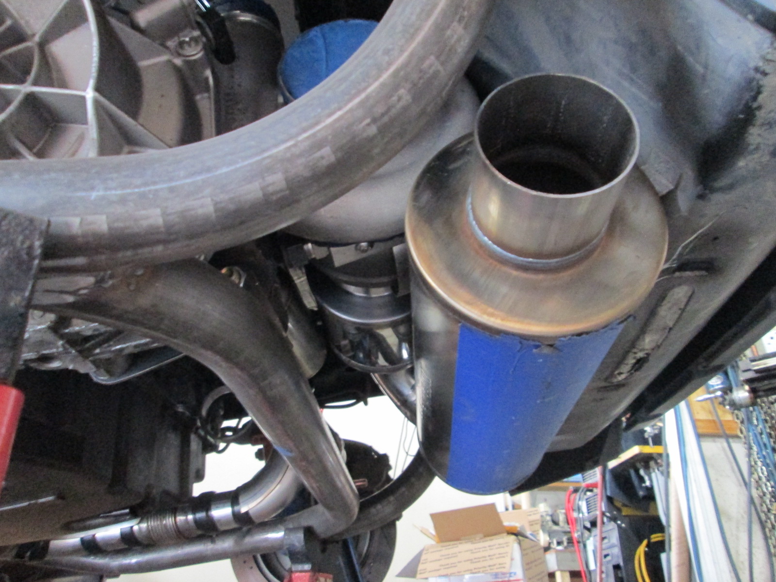
With the mounts done, I needed to test fit the engine in the chassis so I could locate the 3" muffler location. In this picture, the tubes supporting the muffler are clamped to the bottom of the cradle and the muffler is sitting on 1/2" spacers, so it is 1/2" above the bottom of the cradle. At this elevation, there is just enough room to clear the compressor housing with a stainless heat shield on the muffler and the trunk with an aluminum heat shield on it. Overall, I am pretty happy with the clearance.
The cradle still needs several items added to it, so the weight will continue to go up, but it currently is 30.4 lbs.
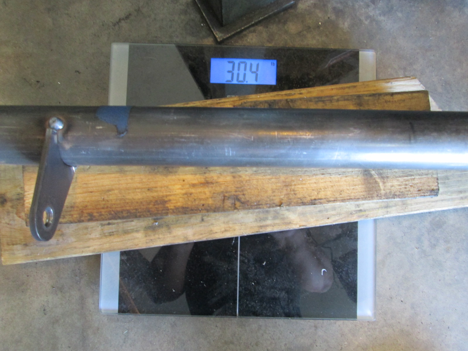
The bare cradle used in my original swap weighs 51.8 lbs.
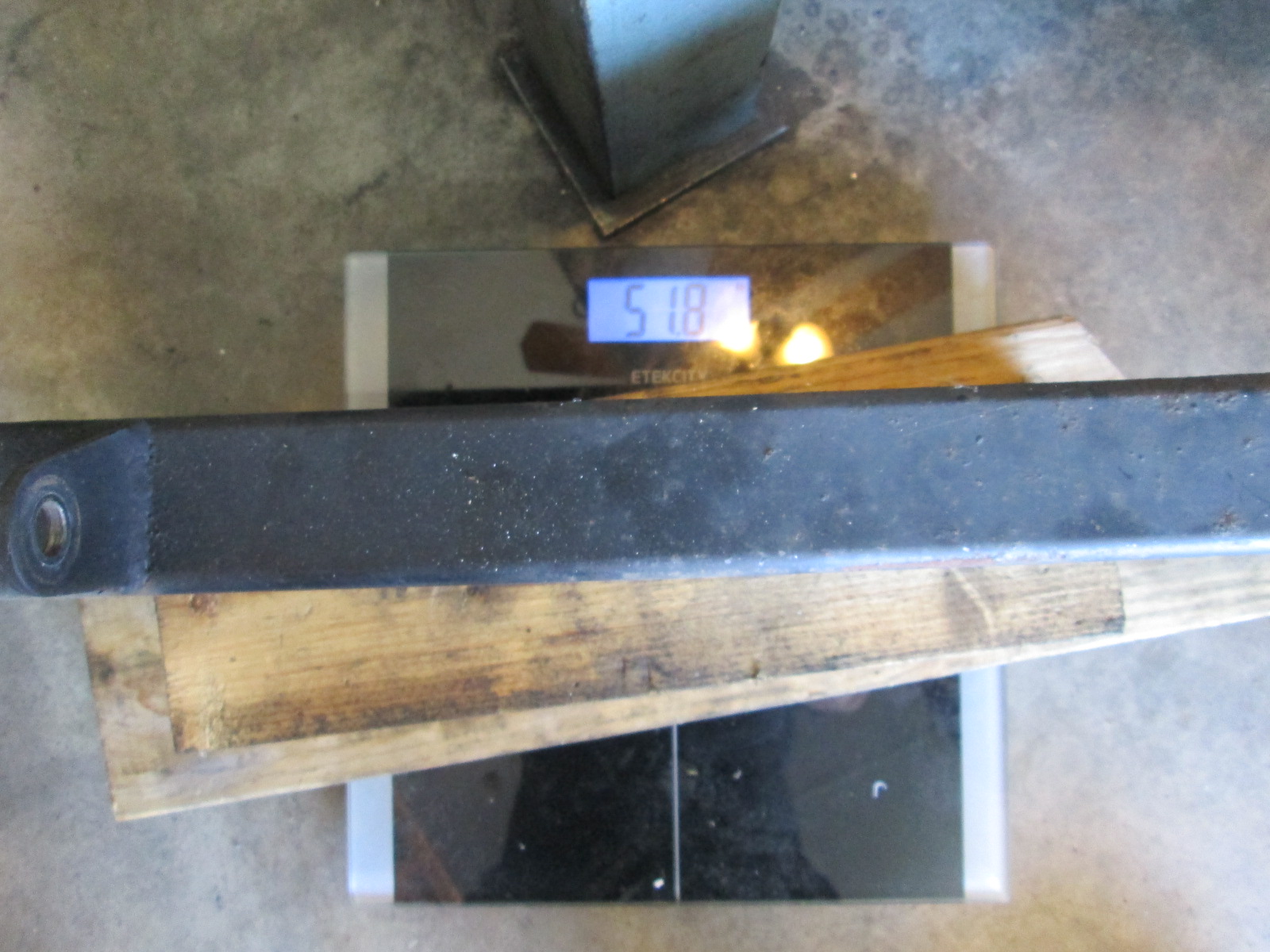
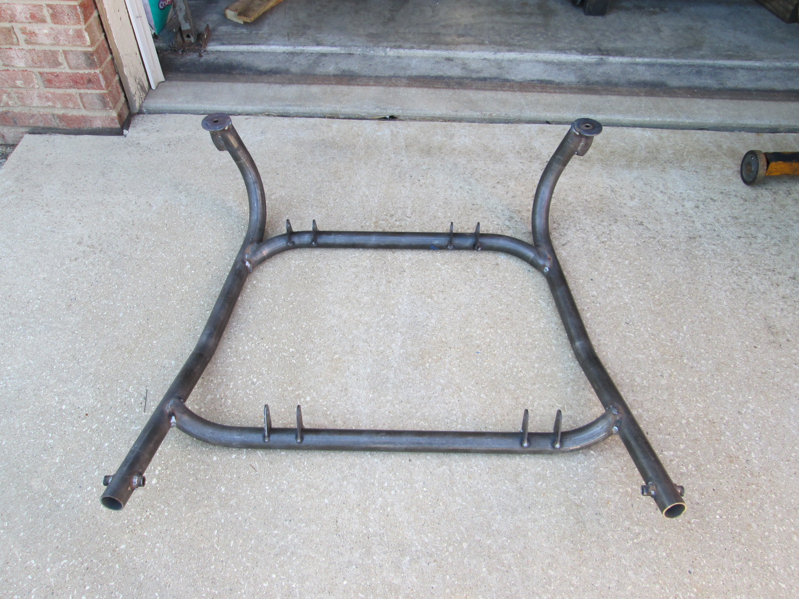
So right now it is 21.8 lbs lighter, but will continue to get heavier. If I can end up with the cradle 15 lbs lighter, that would be awesome! Here is the tubular cradle in its current state. I still need to weld the mount tabs, add the lateral and trailing link suspension tabs, and add a few gusset tubes.
Now that I know where the muffler fits, I can do more exhaust work from the turbo to the 3" muffler.
The cradle still needs several items added to it, so the weight will continue to go up, but it currently is 30.4 lbs.
The bare cradle used in my original swap weighs 51.8 lbs.
So right now it is 21.8 lbs lighter, but will continue to get heavier. If I can end up with the cradle 15 lbs lighter, that would be awesome! Here is the tubular cradle in its current state. I still need to weld the mount tabs, add the lateral and trailing link suspension tabs, and add a few gusset tubes.
Now that I know where the muffler fits, I can do more exhaust work from the turbo to the 3" muffler.
The following 3 users liked this post by fieroguru:
09-20-2020, 03:33 PM
#364
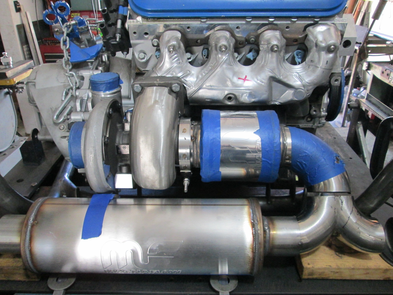
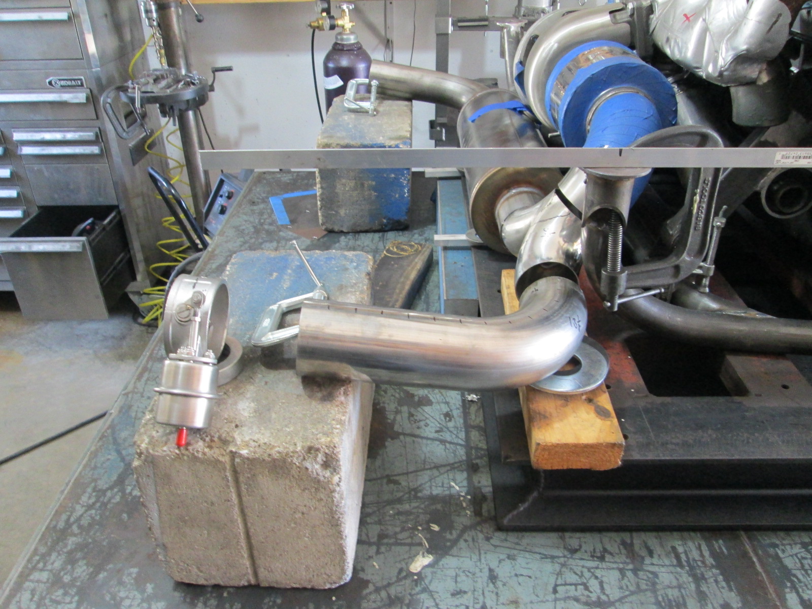
Drivetrain and cradle are back on the table with some rough mockup of the exhaust. The cradle is sitting on the fixture, the muffler is raised 1/2" with the aluminum bars, there is a spacer taped to the muffler to keep it the proper distance from the compressor housing as well as the trunk wall.
Here I added the tailpipes to the setup just to start checking lengths. For reference, the openings in the fascia have a 43" center and the end of the bumper is 20" past the rear cradle mount bolt.
The aluminum angle off the top bolt location of the cradle is 16" (20 would be end of bumper)
I want this swap to be drone free while cruising from 65 to 85 mph in 6th gear, but have zero idea if it will drone or not with the turbo and dual muffler setup. So as I lock down the exhaust setup, I want to leave room to add the proper length helmholtz tube if needed. 65 to 85 is 1700 to 2200 rpm which is 113Hz to 146Hz, which will have the tube length anywhere from 25 3/4" (200 degree exhaust) to 42" (600 degree exhaust). FOr cruise 200 degrees is probably more realistic, that would reduce the length needed to 33.3".
I have two general spots where I could fit a helmholtz resonator.
Preferred option - make cutout tube work as helmholtz when closed. In the picture above, the cutout location at 16" from the cradle bolt (4" from edge of bumper) only gives me about 21". I need to explore options to loop the pipe in the wheel well to add length. The cutout needs to be hidden for stealth purposes.
The other option is to trim down the right flange on the 3" muffler so I can move the muffler more to the center and create room at the exit of the muffler for a 3" 90. Then I can run the dedicated helmholtz tube in the space in front of the muffler (and below the sway bar). This location would allow 30+ inches w/o any additional loops. I think I will go ahead and move the muffler so I can pick from either option at a later date.
The following users liked this post:
Project GatTagO (09-20-2020)
09-20-2020, 04:56 PM
#365
Launching!

It's good to see you dropping that many pounds off the cradle. I wonder if a mid/rear engine car has much of a problem w/ drone to begin with. The pipes are so much shorter and dont run under the passenger compartment. Hopefully you wont have to mess with it.
09-26-2020, 06:30 PM
#367
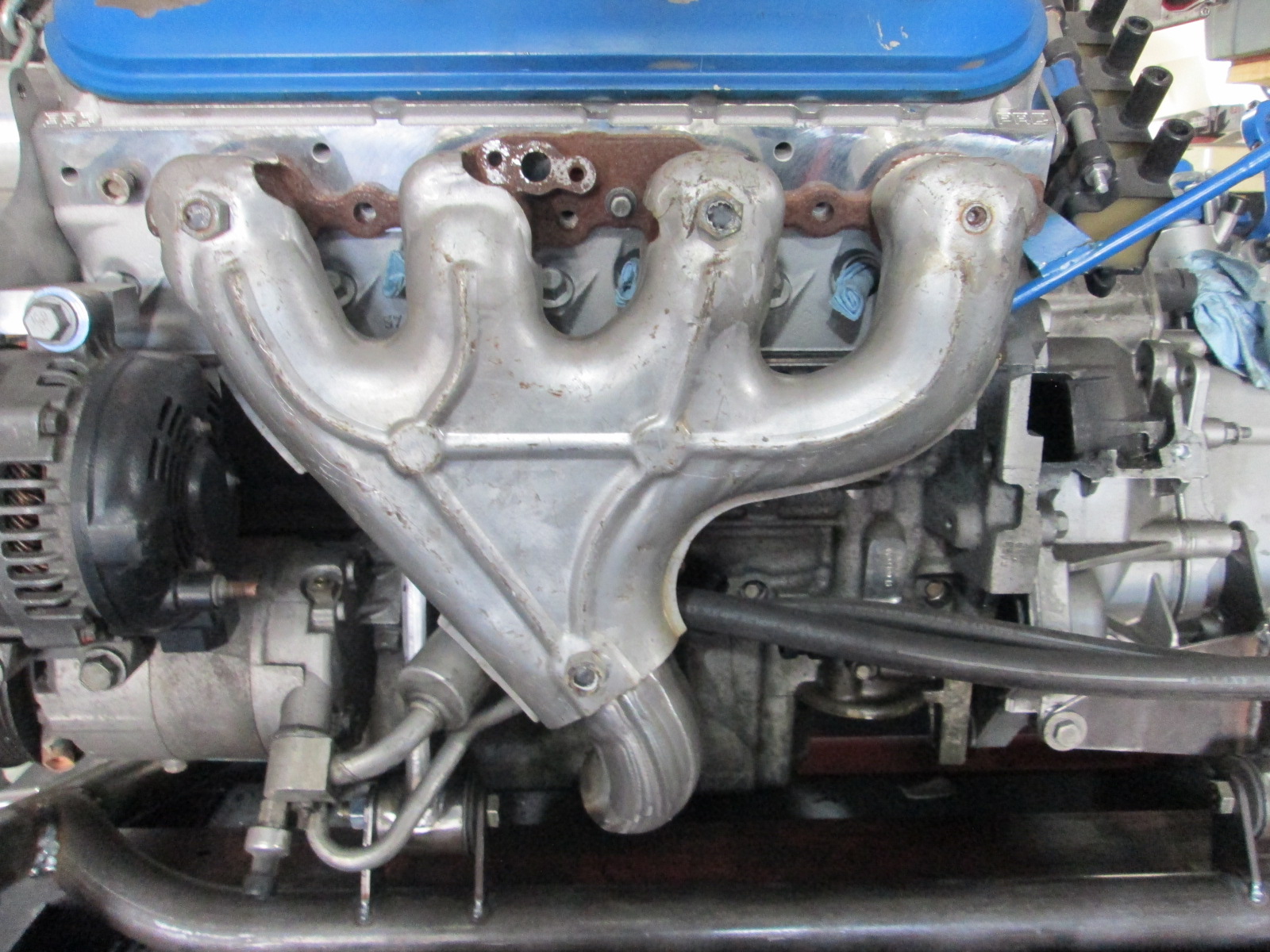
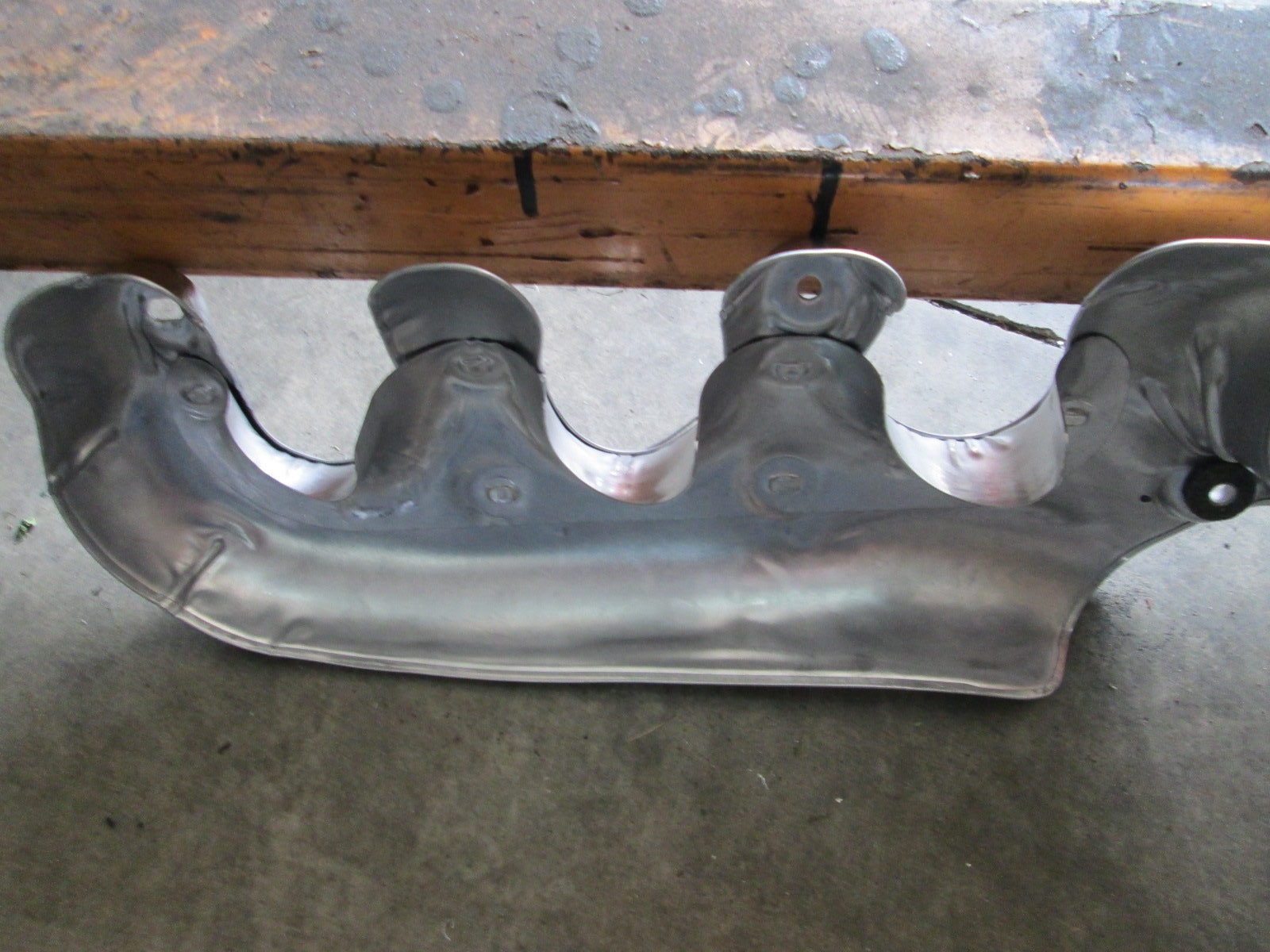
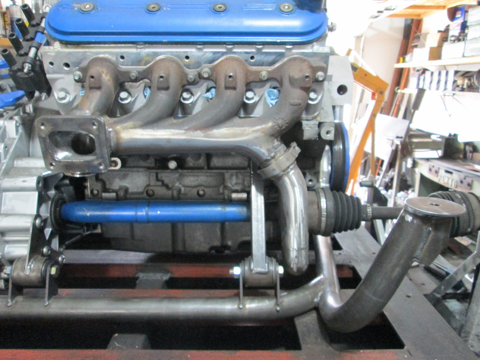
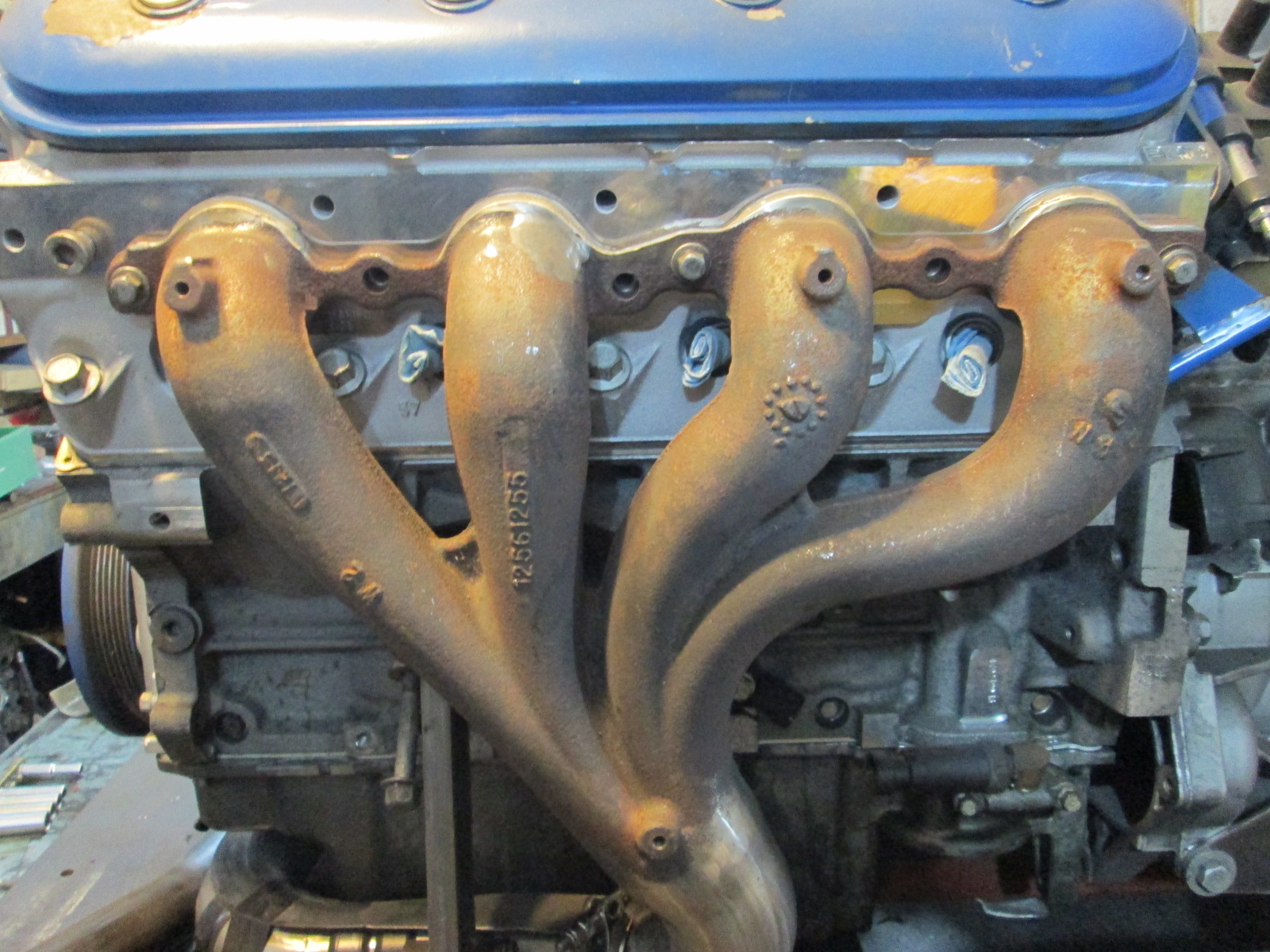
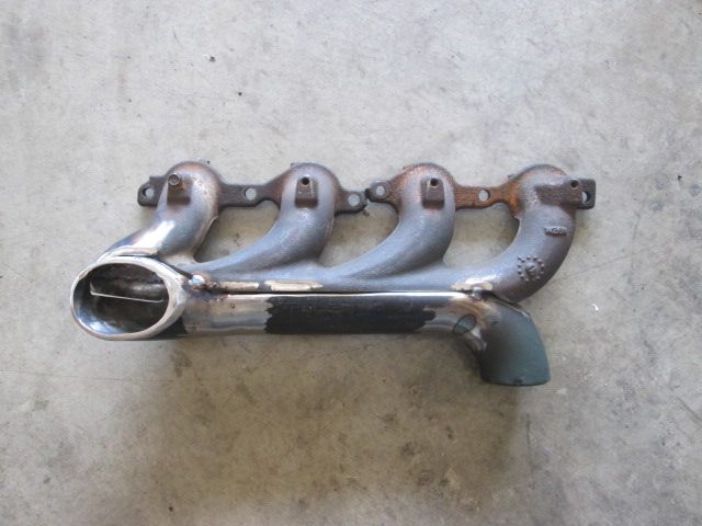
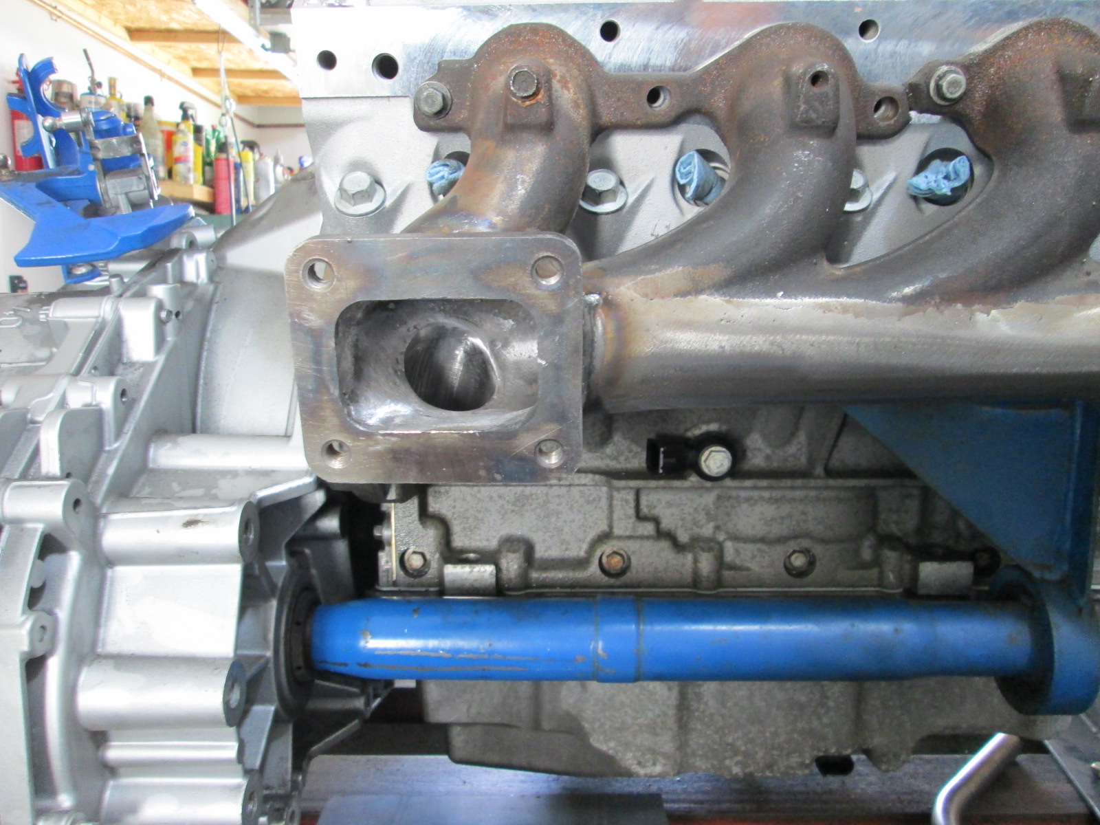
Started more work on the exhaust. I had been planning to use the LS7 manifold for the front bank like my old swap did, but I didn't really like idea of the necking the large oval collector down to a 2" tube to crossover to the rear bank. After looking at options, I decided to use one of my LS6 cast manifolds. They flow good, are cast steel to help retain heat, have factory heat shields, and the collector is 2.5".
When I was determining the alternator location, I test fit every stock manifold I had, so they all would fit. This would be the easy solution:
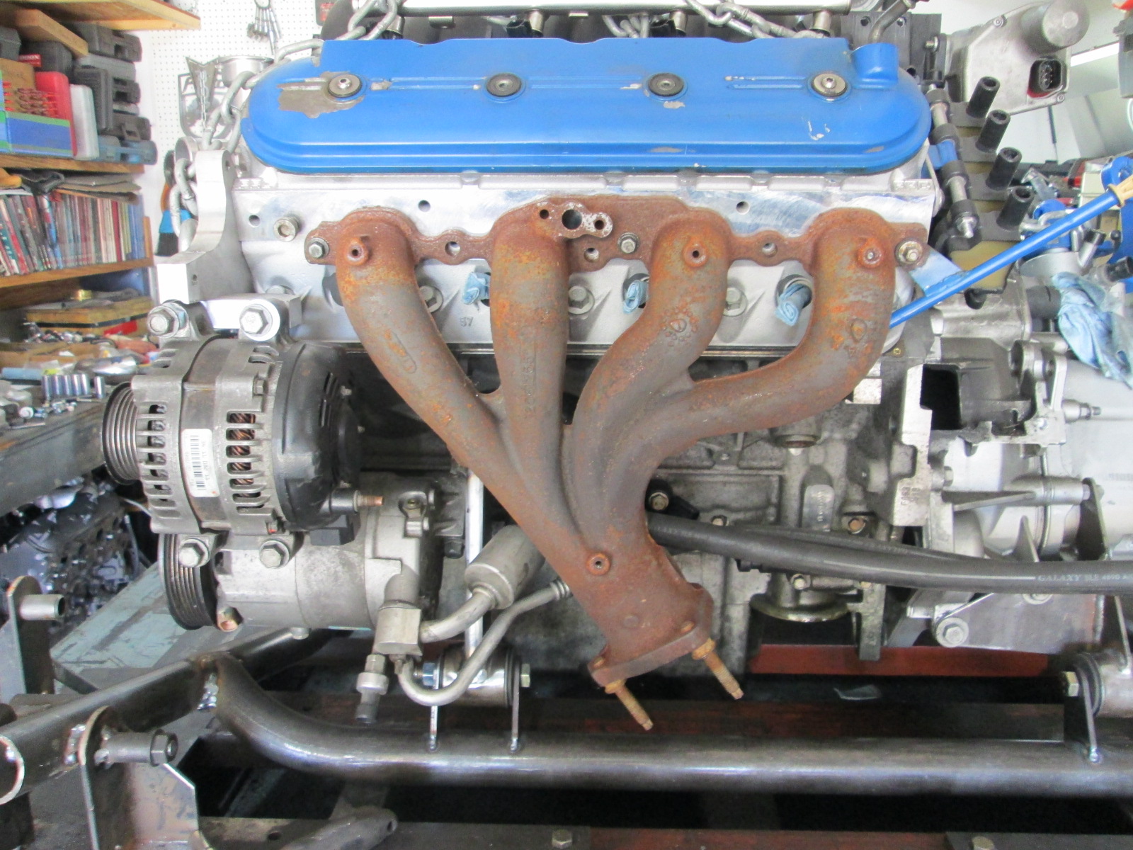
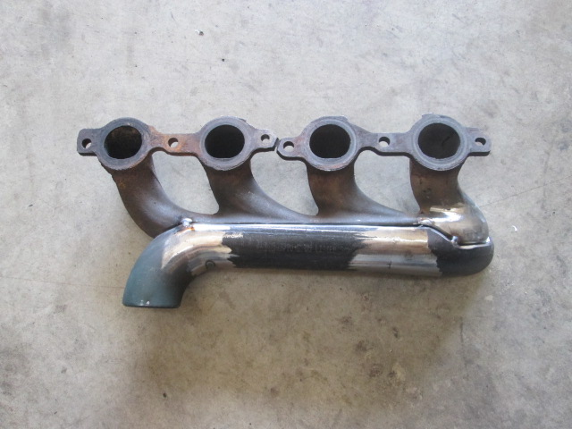
The manifold was a little long and I don't like factory collector connections, plus I wanted the outlet to point to the rear of the front crossmember, and I wanted the outlet closer to 2" ID. So I took the hard way...
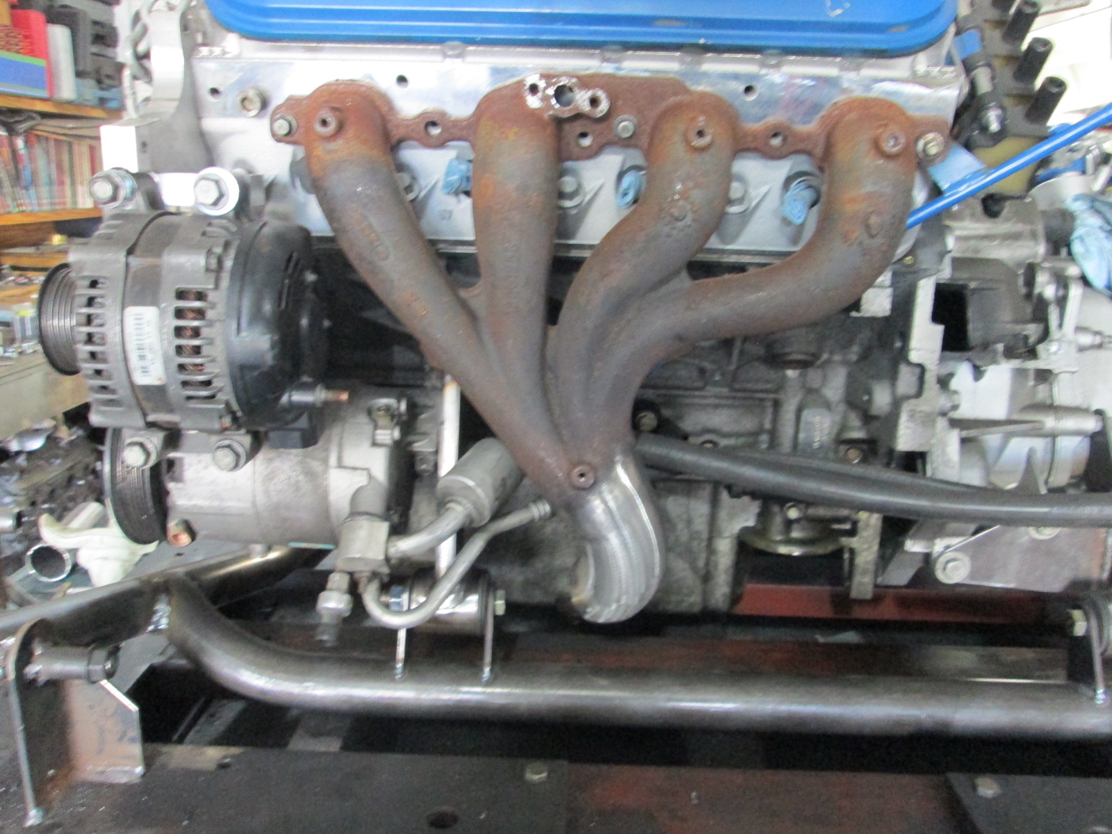
The 90 started out as a 2" Schedule 10 stainless 90. The ID is about 2.15", so I enlarged the inlet side to 2 1/2" ID and reduced the outlet end to just under 2". Lots of cutting, welding, grinding and smoothing... but I think the end result was worth it.
I will likely buy a new (or nicer) factory heat shield. I will also tack a 16ga stainless heat shield on the backside to help keep the AC lines and wiring away from excessive temps. I also have to weld shut the egr passage.
When I was determining the alternator location, I test fit every stock manifold I had, so they all would fit. This would be the easy solution:
The manifold was a little long and I don't like factory collector connections, plus I wanted the outlet to point to the rear of the front crossmember, and I wanted the outlet closer to 2" ID. So I took the hard way...
The 90 started out as a 2" Schedule 10 stainless 90. The ID is about 2.15", so I enlarged the inlet side to 2 1/2" ID and reduced the outlet end to just under 2". Lots of cutting, welding, grinding and smoothing... but I think the end result was worth it.
I will likely buy a new (or nicer) factory heat shield. I will also tack a 16ga stainless heat shield on the backside to help keep the AC lines and wiring away from excessive temps. I also have to weld shut the egr passage.
09-27-2020, 03:45 PM
#368
The new rear heat shield showed up today. It is actually from the 2015+ LT series truck engines, but it should be able to be made to work. I like the smoother look as well as the heat shield extends deeper into the plug openings.
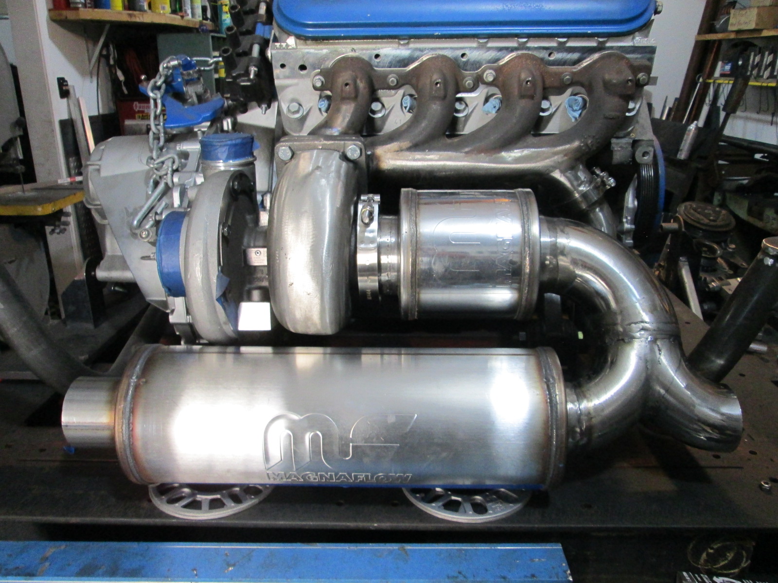
Also started routing the 2" exhaust from the front manifold. Got the V-band, the first bend and a section of tube to the location of the 2nd bend roughed in.
Also started welding the mufflers to the elbows. Notice I did cut back the flange for the 3" muffler as discussed.
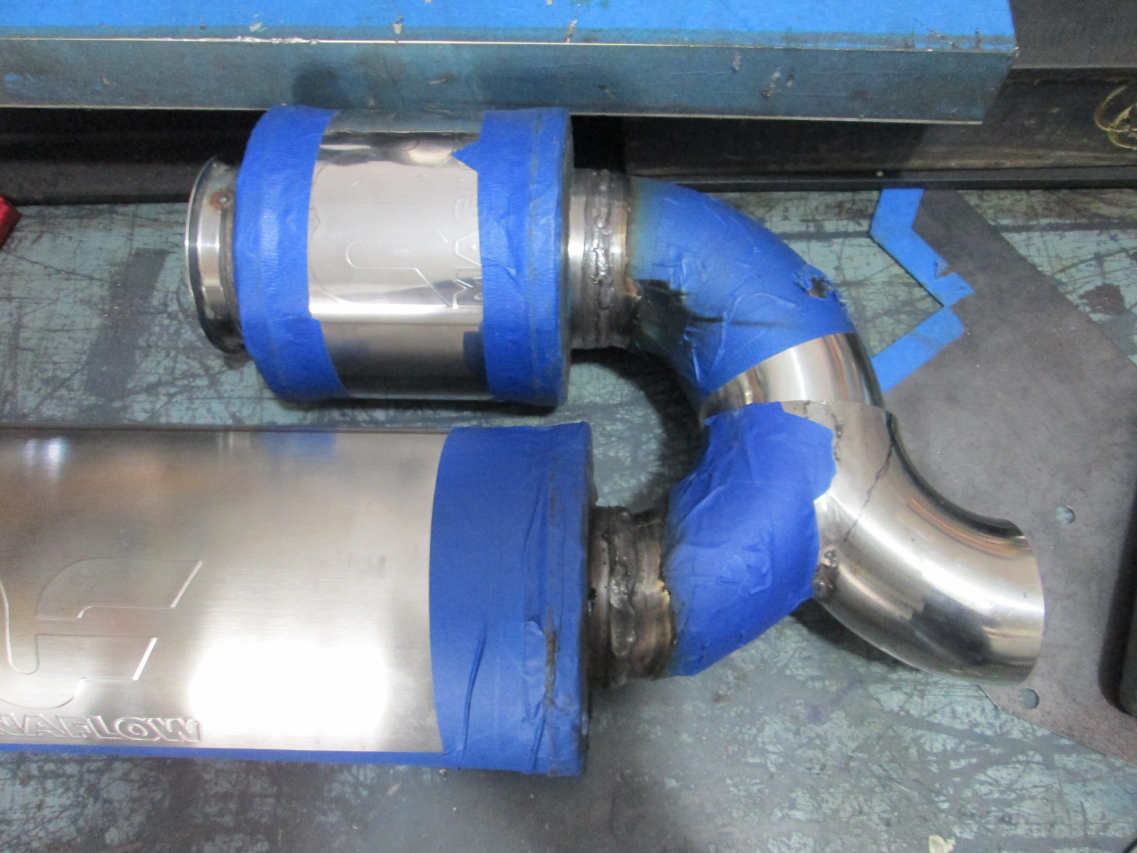
Also started routing the 2" exhaust from the front manifold. Got the V-band, the first bend and a section of tube to the location of the 2nd bend roughed in.
Also started welding the mufflers to the elbows. Notice I did cut back the flange for the 3" muffler as discussed.
10-03-2020, 03:38 PM
#369
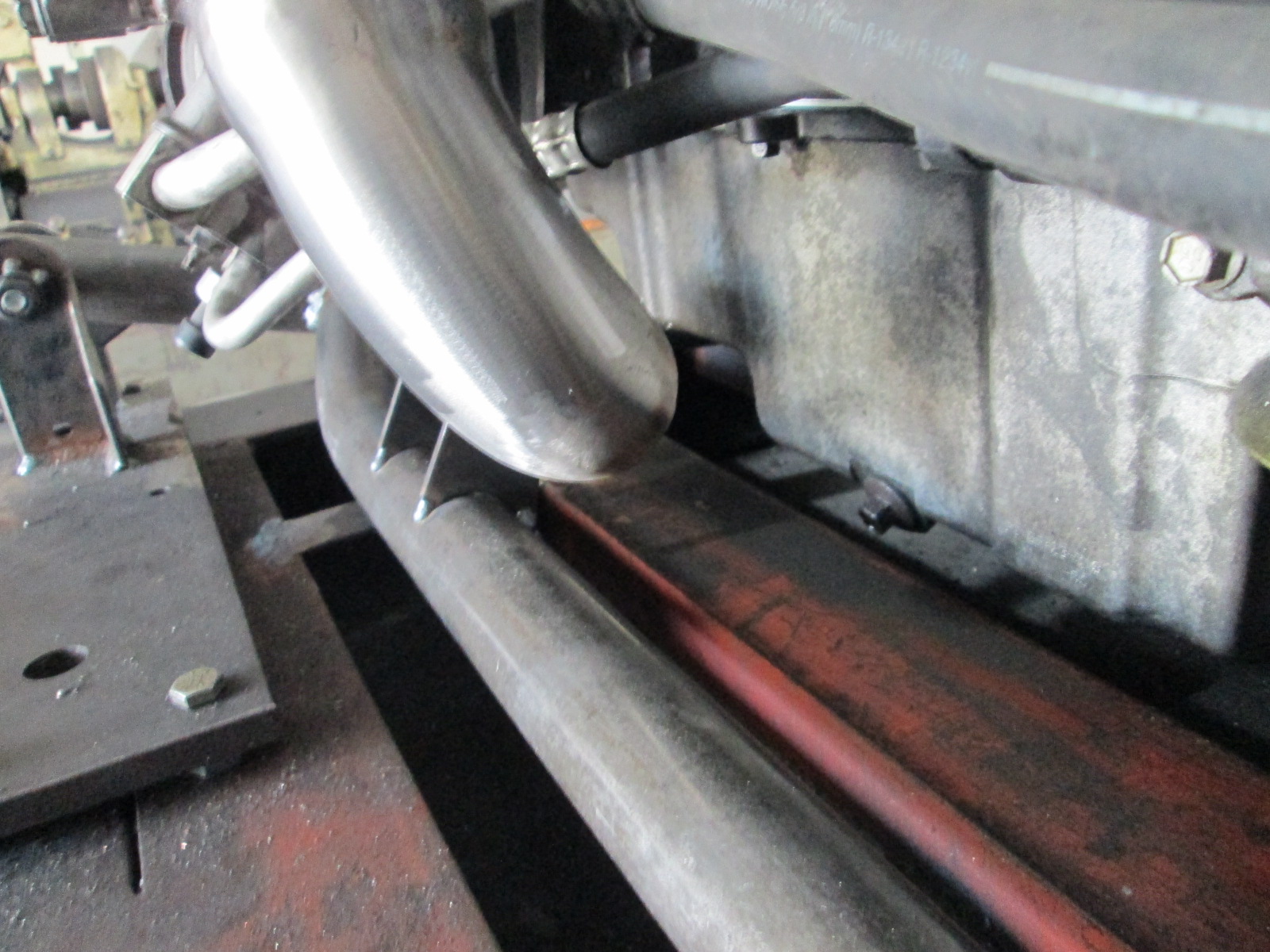
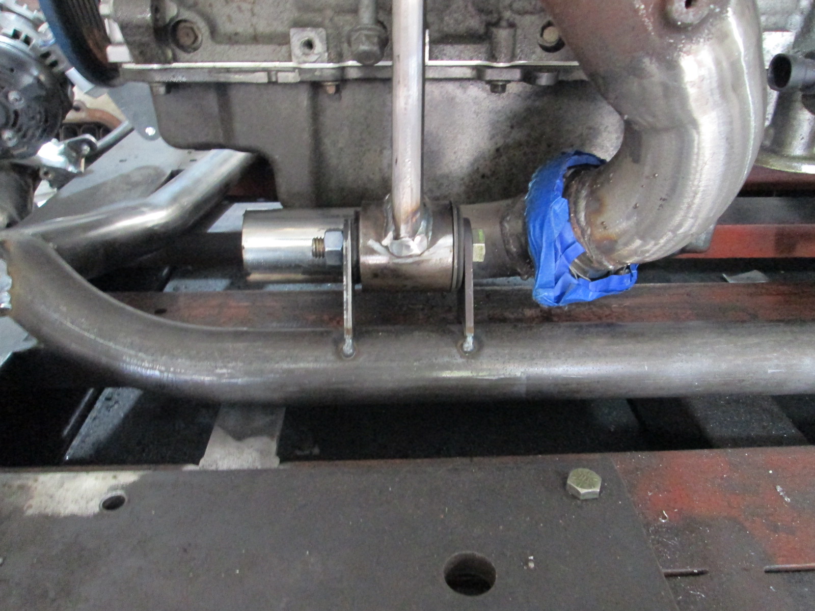
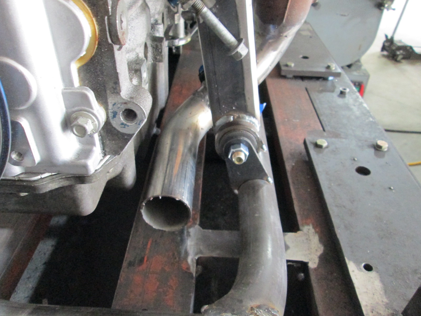
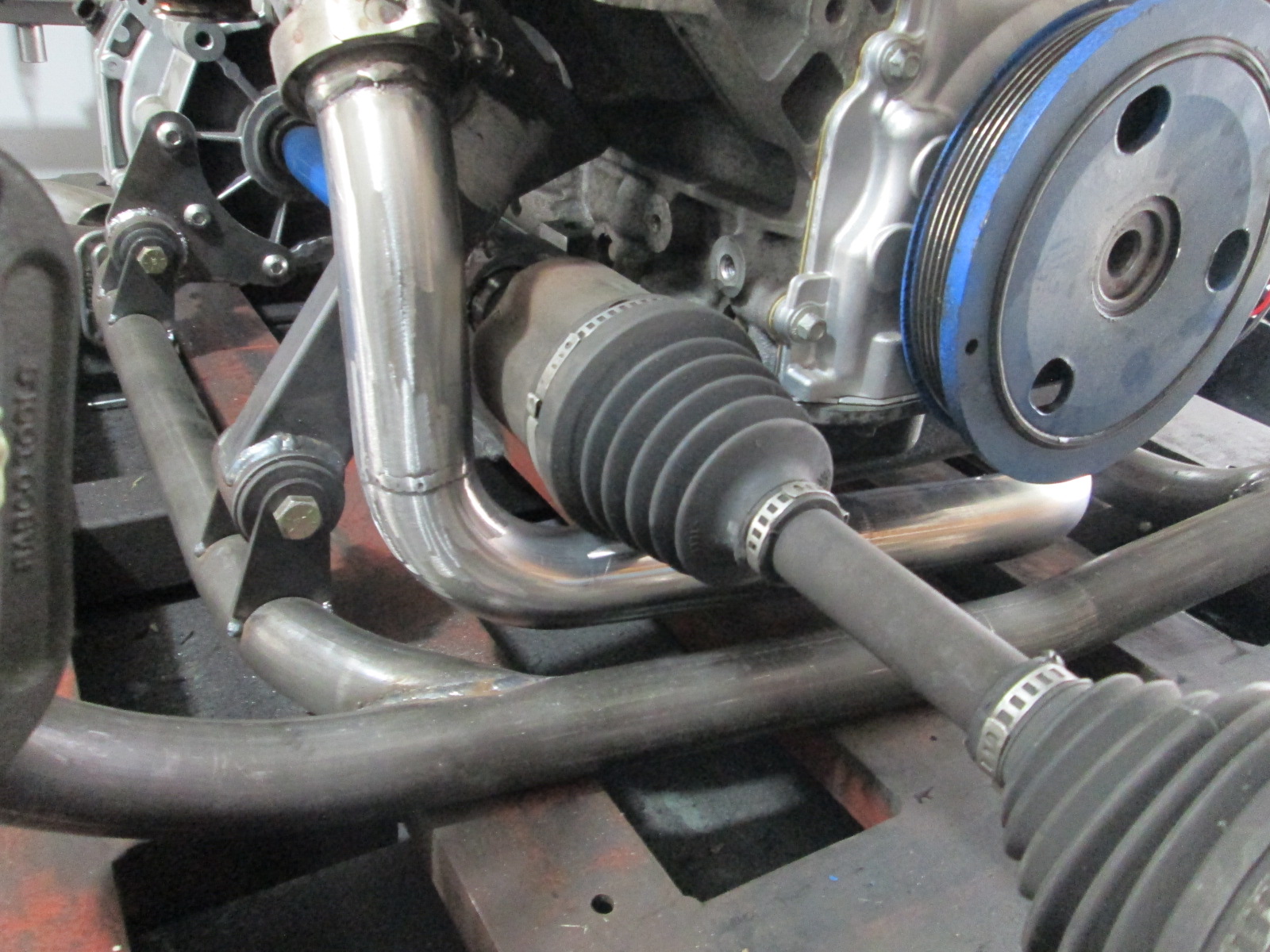
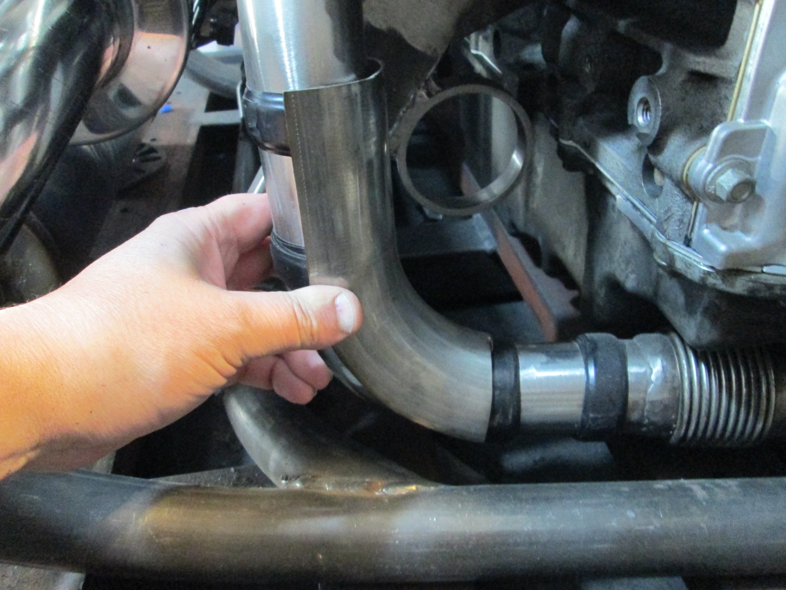
Crossover exhaust pipe is done, except for the heat shields around the oil pan and the tripot housing. It is 1" above the bottom of the cradle.
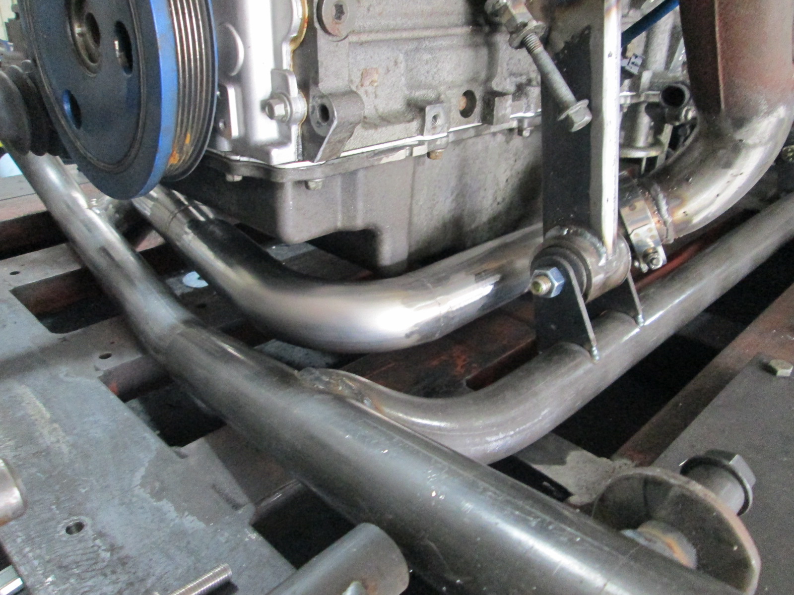
I also started to remove the egr pocket. I welded the ports closed on the two center runners and have started to trim away the excess material. Still a little fine tuning to this area is needed.
I also started to remove the egr pocket. I welded the ports closed on the two center runners and have started to trim away the excess material. Still a little fine tuning to this area is needed.
10-04-2020, 06:06 AM
#370
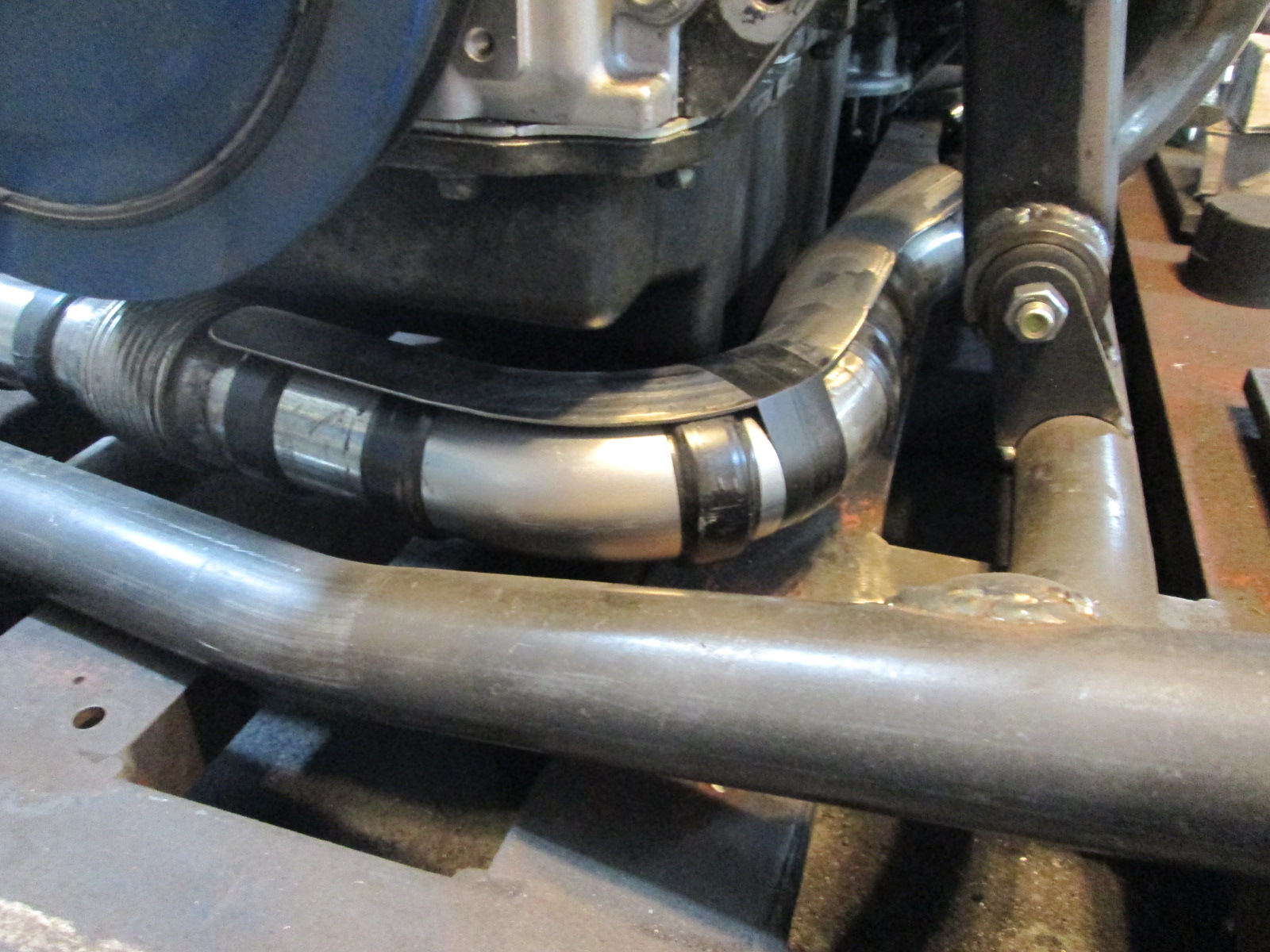
Did you give any thought to a flex connector in that crossover leg? I suspect thermal expansion is going to put some part of that between a rock and hard place which will likely result in something cracking. Acquaintance of mine pic below. Note the flex joint in the crossover from the passenger side to the driver's side/turbo mount. Repeated cracking issues until he added it. Just a thought.
Last edited by Michael Yount; 10-04-2020 at 06:37 AM.
10-04-2020, 06:58 AM
#371

So right now it is 21.8 lbs lighter, but will continue to get heavier. If I can end up with the cradle 15 lbs lighter, that would be awesome! Here is the tubular cradle in its current state. I still need to weld the mount tabs, add the lateral and trailing link suspension tabs, and add a few gusset tubes.
12-20-2020, 02:23 PM
#372
Haven't had much time to work on the car, but slowly making progress.
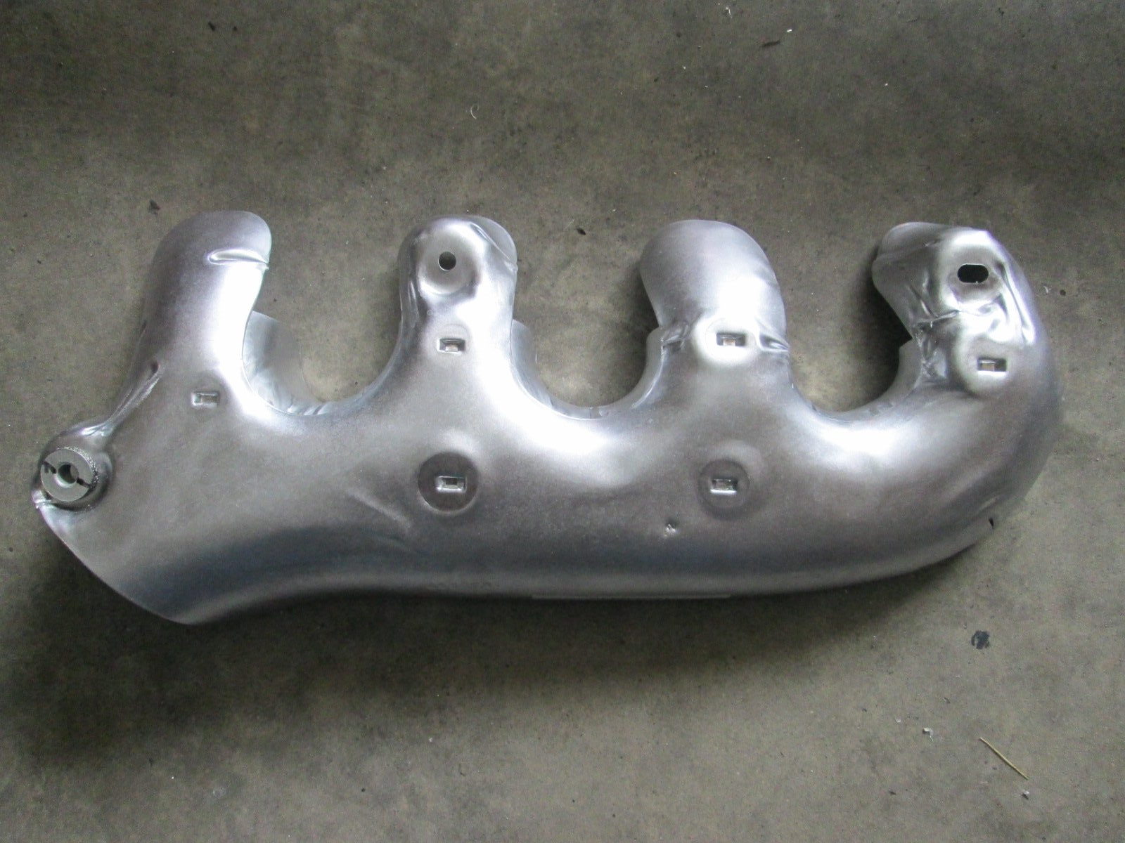
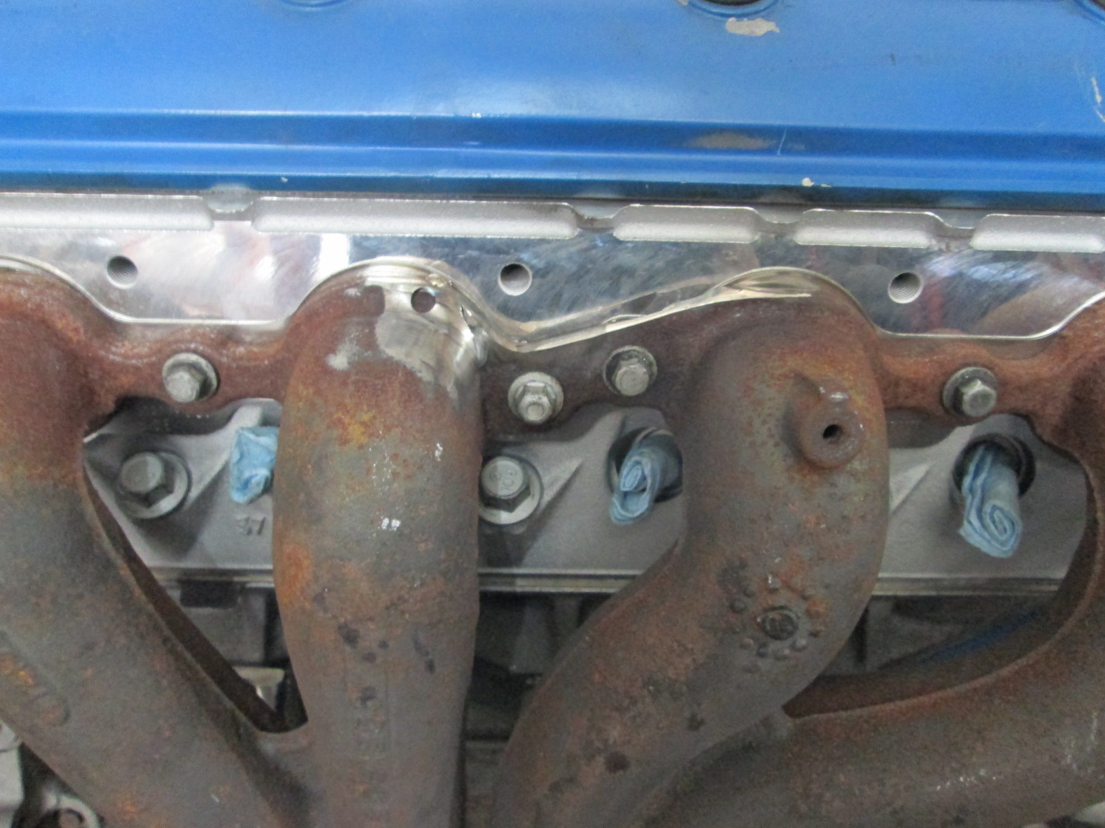
One of the projects that took far longer than needed (and wasn't really needed) was cleaning up the front manifold. The stock LS6 front manifold had an EGR connection and passage on the backside. The tops of the primary flange at the ports was more oval than round and let the top of the gasket stick out about 1/8". Even though this manifold will be up front and not visible, I took the time to make it look nicer (and gasket match them to the LS7 MLS exhaust gaskets).
Before:
After:
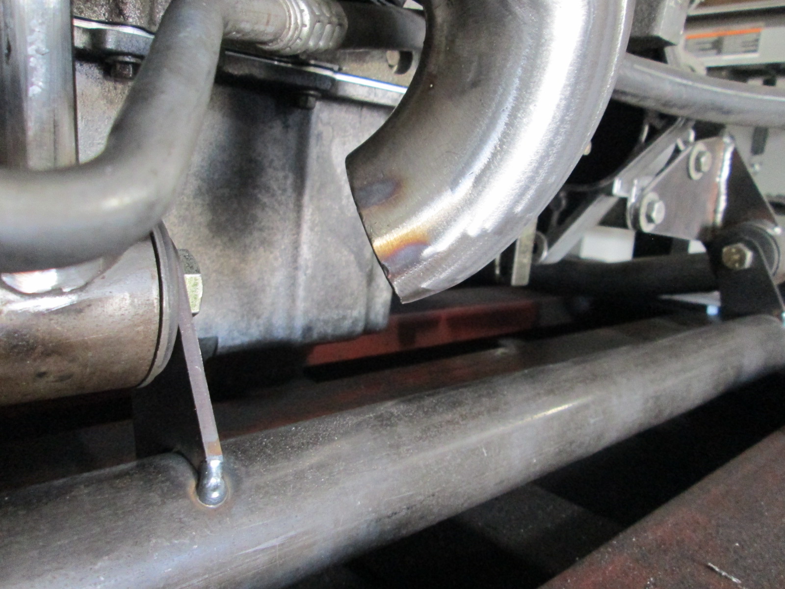
The rear exhaust is starting to get welded up.
The heat shields between the exhaust and the oil pan and tripot joint are coming along, but still need more work. I did add a bellows to the crossover pipe.
One of the projects that took far longer than needed (and wasn't really needed) was cleaning up the front manifold. The stock LS6 front manifold had an EGR connection and passage on the backside. The tops of the primary flange at the ports was more oval than round and let the top of the gasket stick out about 1/8". Even though this manifold will be up front and not visible, I took the time to make it look nicer (and gasket match them to the LS7 MLS exhaust gaskets).
Before:
After:
The rear exhaust is starting to get welded up.
The heat shields between the exhaust and the oil pan and tripot joint are coming along, but still need more work. I did add a bellows to the crossover pipe.
Last edited by fieroguru; 12-20-2020 at 03:15 PM.
12-20-2020, 02:54 PM
#373
TECH Senior Member

Nice job on the manifold, which, by the way, is one of the smoothest designs I've seen in a while! What was the OEM app for those? You likely have it listed somewhere but I have no idea how far back to look.
 12-20-2020, 03:45 PM
#374
Thanks!
The front manifold is from the driver side of the LS6 Vette.
The rear turbo manifold started life as a passenger side truck manifold.
It was a lot of work, but worth it as this highly modified truck manifold allows me to fit the turbo in a largely hidden location and keep my stock truck.
I cut the the entire bottom section of the manifold off (as well as a portion of the #8), took a 2 1/2" section of schedule 40 pipe, cut it in half as well and tapered it to down to merge with a 2" schedule 40 bend on one end. Lots of trimming around the last port and shaping the transition into the T4 flange.
The following users liked this post:
Project GatTagO (12-21-2020)
The following users liked this post:
Project GatTagO (12-21-2020)
12-21-2020, 12:02 PM
#376
TECH Fanatic
iTrader: (27)

I love seeing the updates for this project! Nicely done on the clean up of the manifolds. You can barely tell anything was even there. If you hadn't mentioned it, I wouldn't have picked up on it.
The following users liked this post:
Project GatTagO (12-21-2020)
04-25-2021, 07:06 PM
#377
Been 5 months since the last update... not as much progress as I would have liked.
The cradle is ready for another test fit to finalize the exhaust tip placement, but before doing that I went down a rabbit hole with the rear suspension.
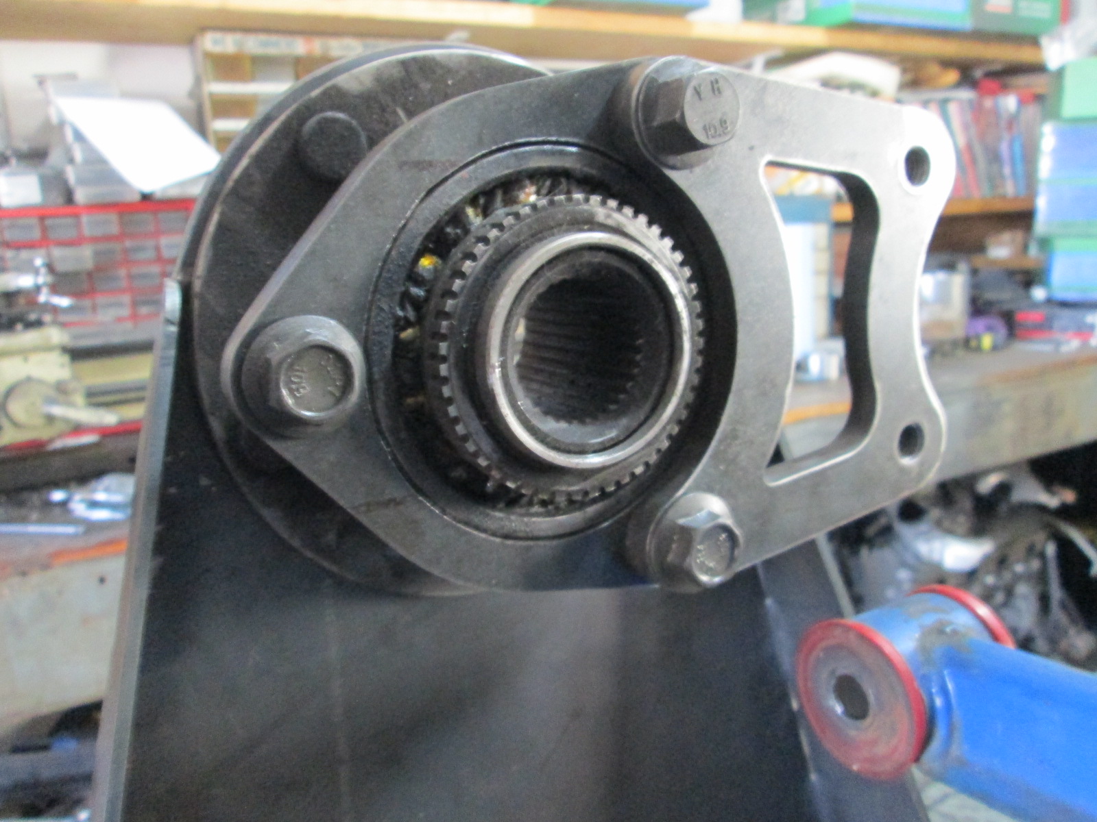
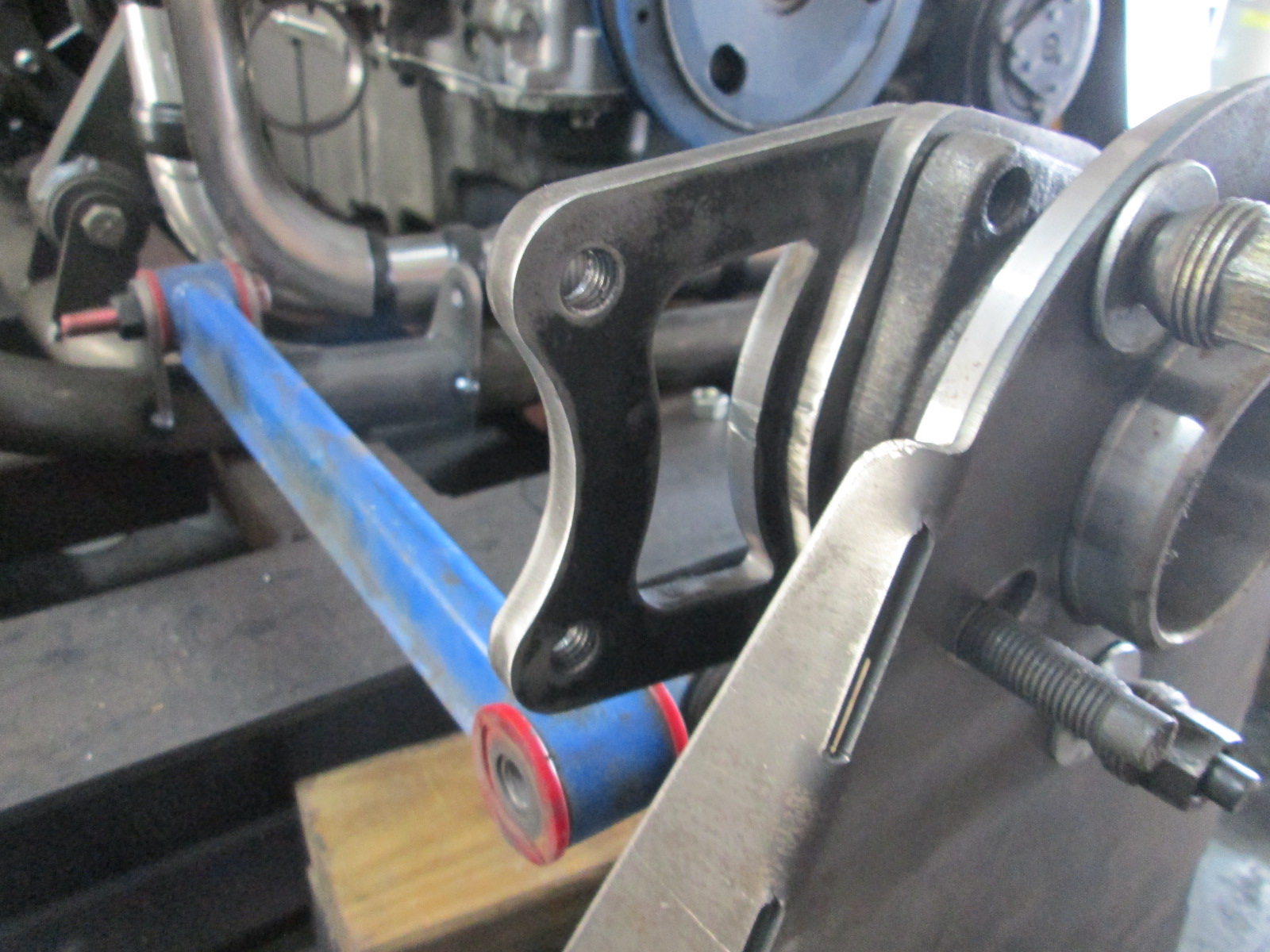
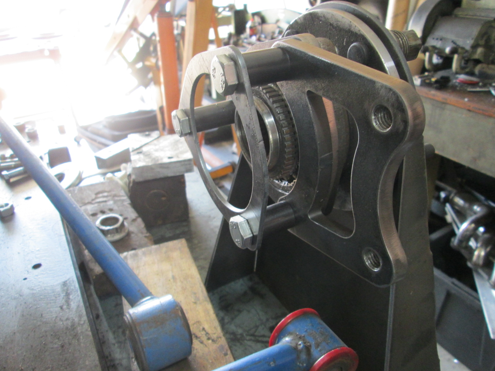
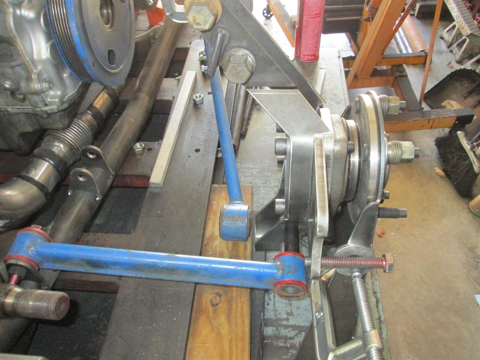
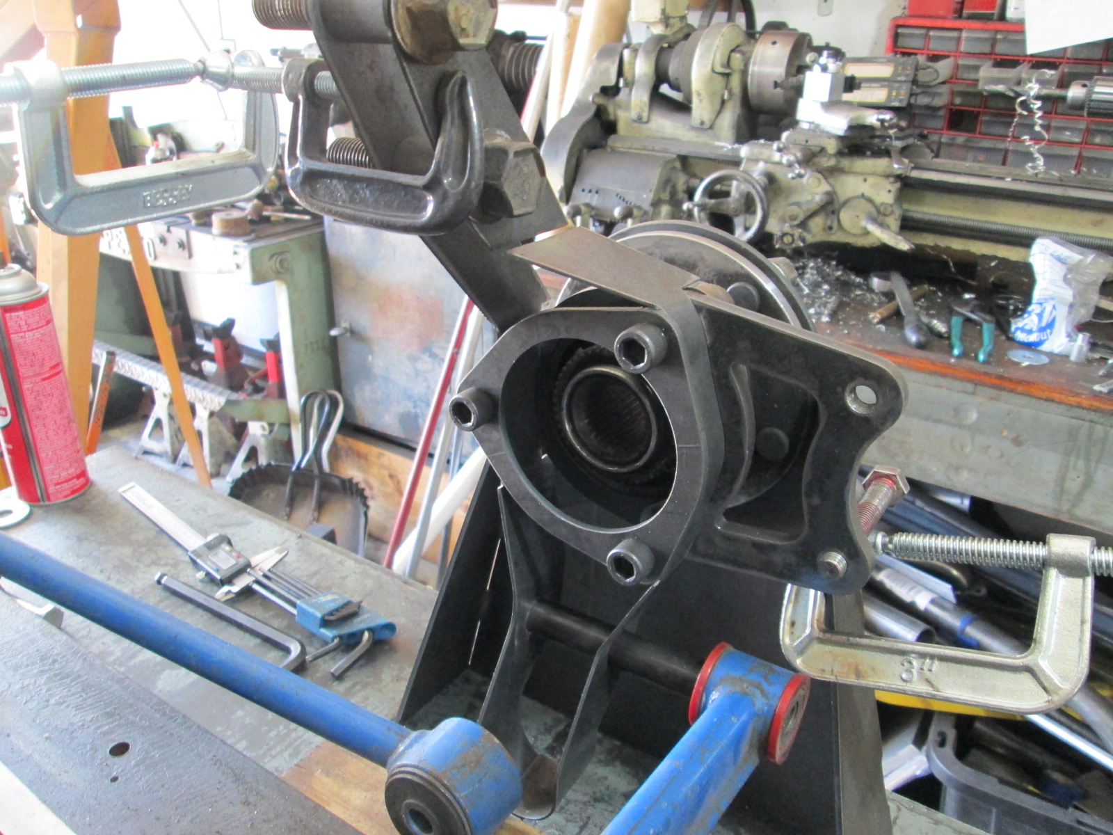
I want stronger wheel bearings, stronger CV housings, ABS sensors (for RaceTCS traction control) and none of that will fit the stock knuckles front/rear. C5 wheel bearings on all 4 corners is where I am heading.
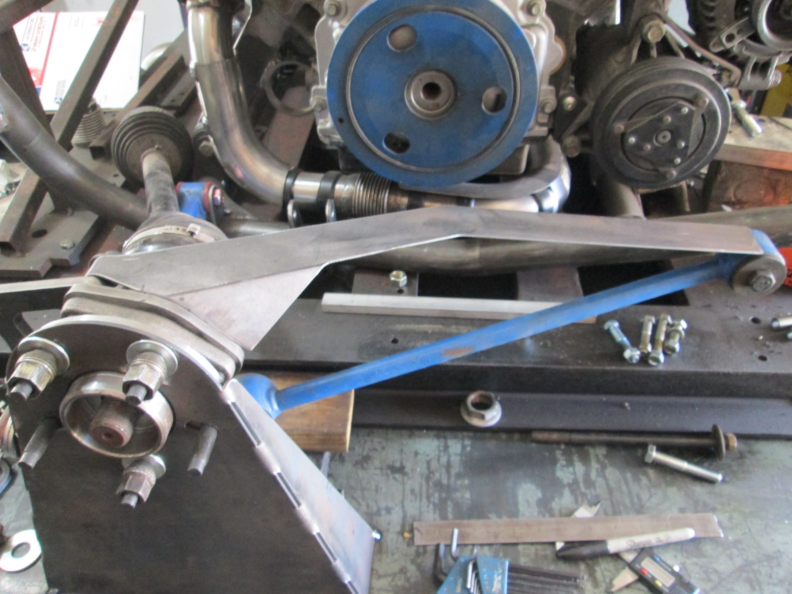
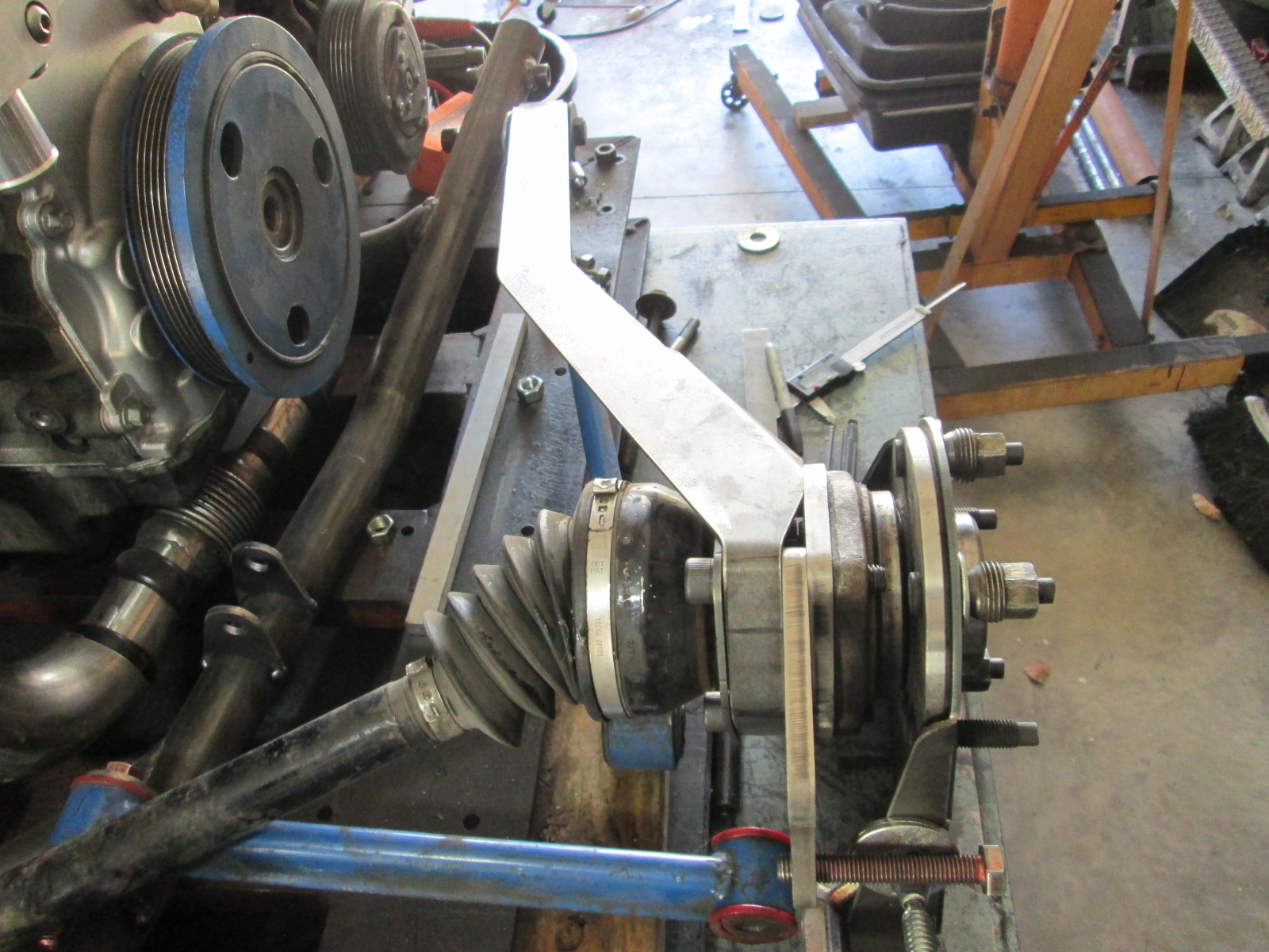
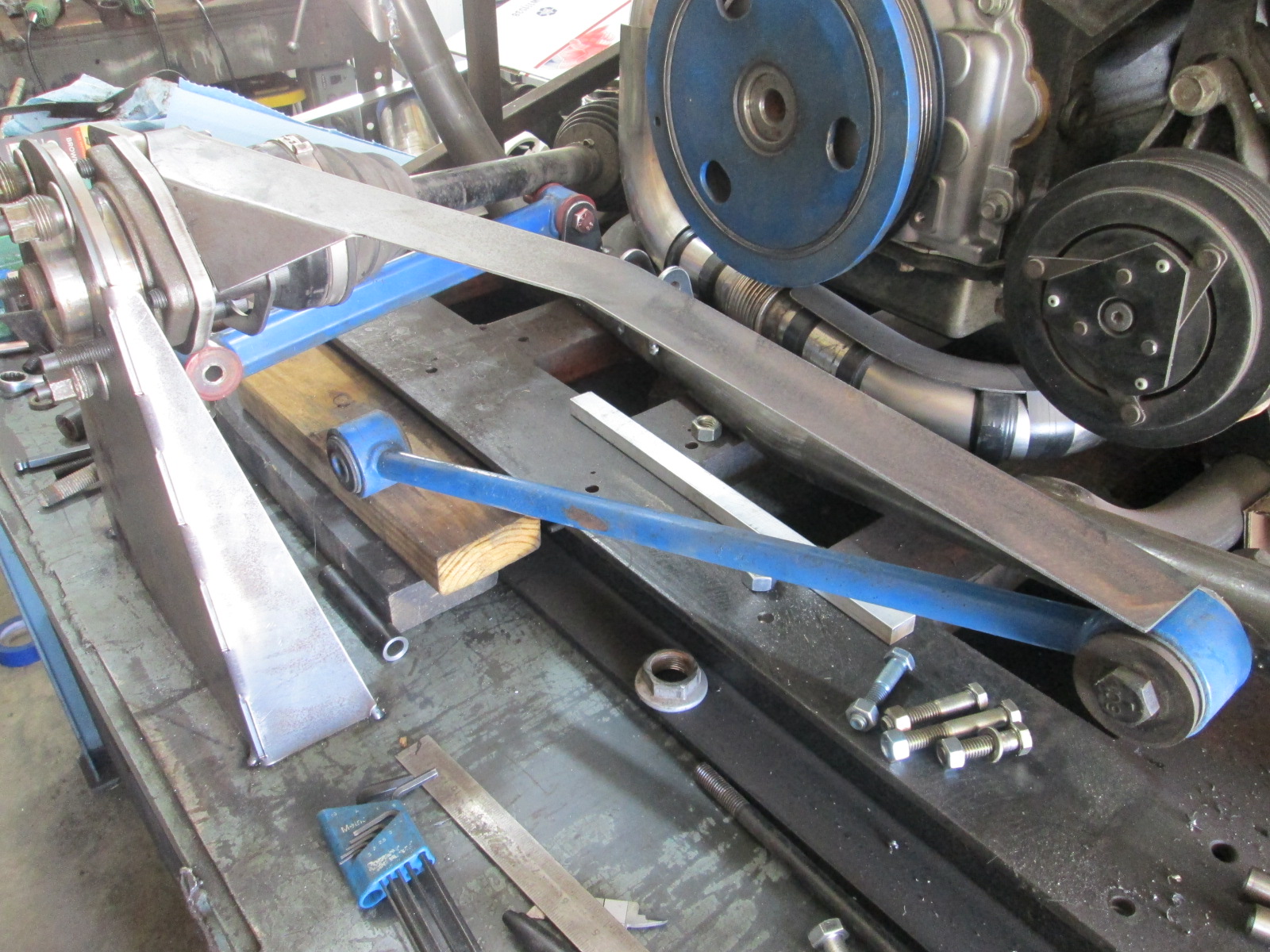
First step was to locate the stock rear suspension (made this stand on my CNC plasma!):
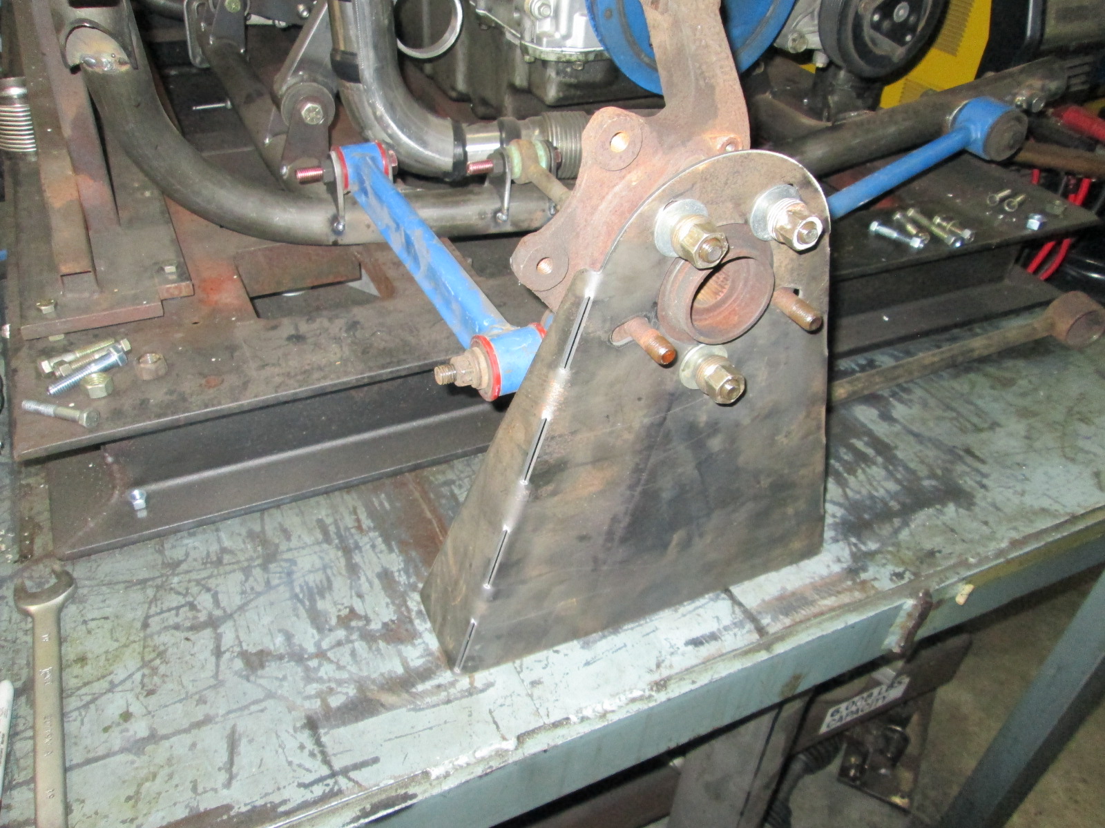
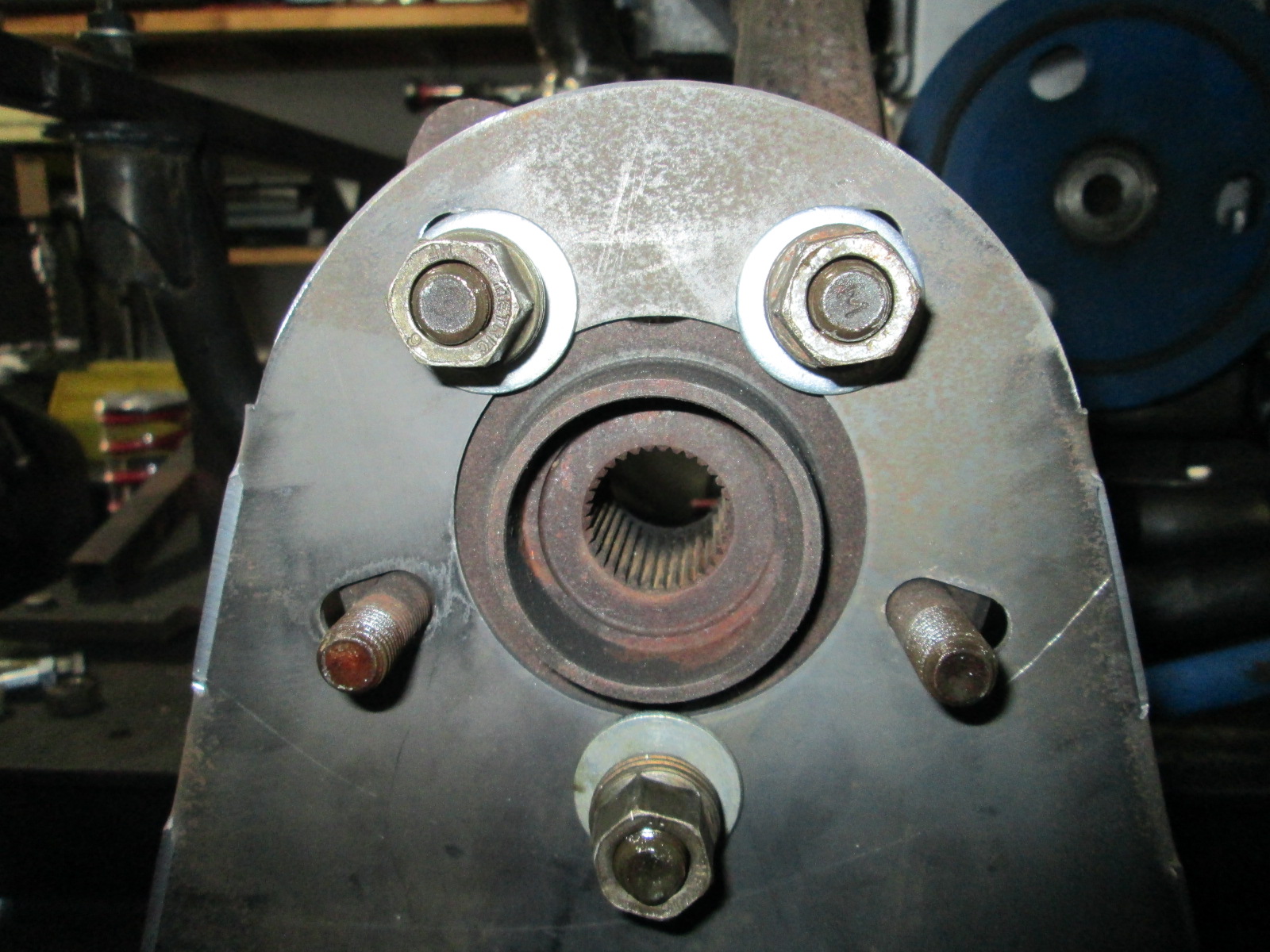
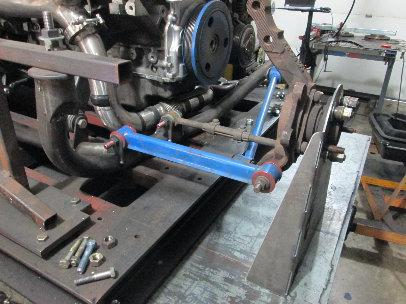
Then I started mocking up an old C5 wheel bearing that I removed the ABS sensor from a while back:
Been playing around with a couple of options on the rear suspension.
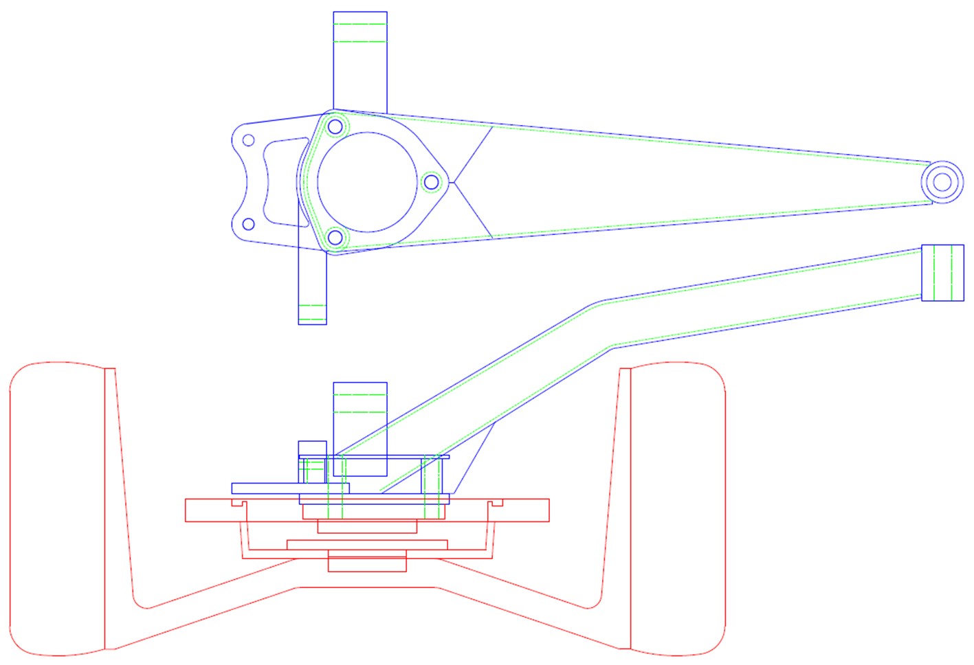
Option 1: Strut based knuckle that incorporates a 1 1/2" drop, caliper position for 13" rotors and is based on the using the C5 wheel bearings:
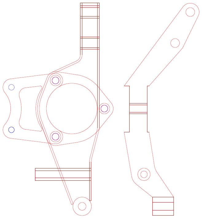
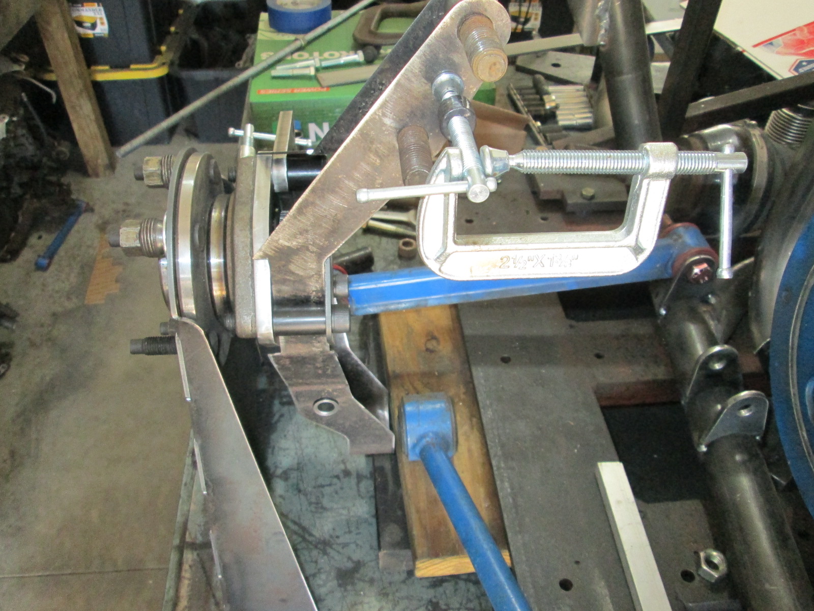
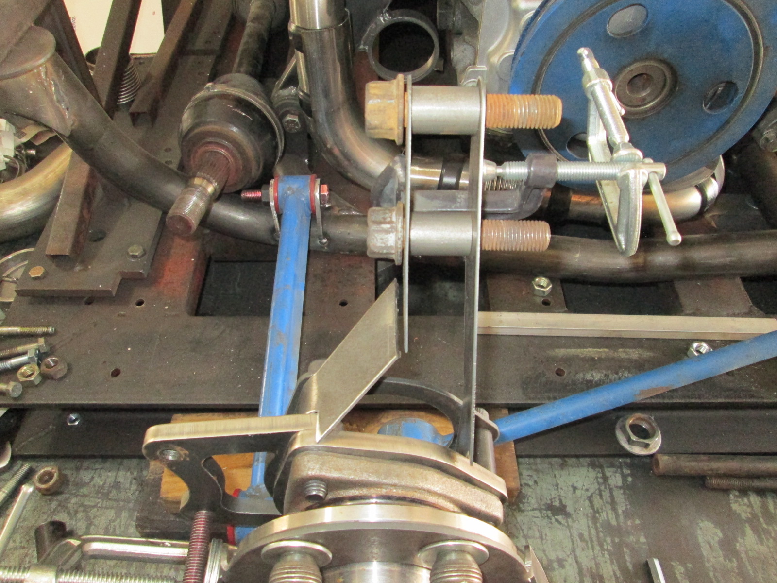
Option 2: A 3 link setup similar to the C3 rear, but without using the axles as a suspension link. :
The cradle is ready for another test fit to finalize the exhaust tip placement, but before doing that I went down a rabbit hole with the rear suspension.
I want stronger wheel bearings, stronger CV housings, ABS sensors (for RaceTCS traction control) and none of that will fit the stock knuckles front/rear. C5 wheel bearings on all 4 corners is where I am heading.
First step was to locate the stock rear suspension (made this stand on my CNC plasma!):
Then I started mocking up an old C5 wheel bearing that I removed the ABS sensor from a while back:
Been playing around with a couple of options on the rear suspension.
Option 1: Strut based knuckle that incorporates a 1 1/2" drop, caliper position for 13" rotors and is based on the using the C5 wheel bearings:
Option 2: A 3 link setup similar to the C3 rear, but without using the axles as a suspension link. :
04-25-2021, 08:07 PM
#378
TECH Senior Member
Planning a little intensive auto-X work? They won't know what hit them....
The following users liked this post:
JoshHefnerX (04-25-2021)
05-02-2021, 07:23 PM
#379

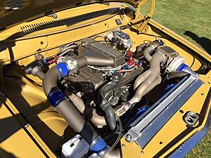
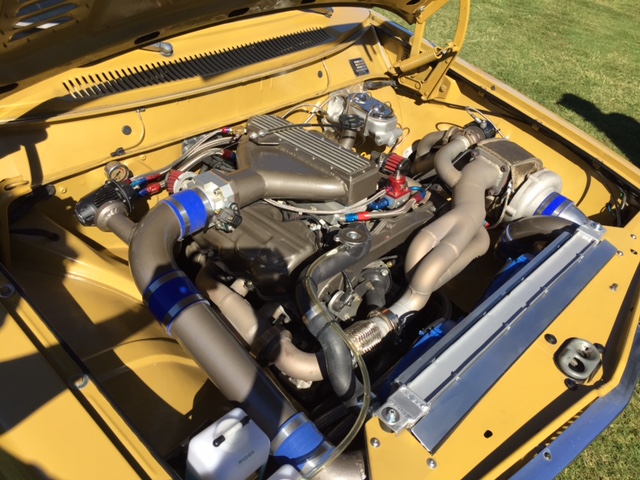
Nothing to see here... just a puny 5.3 with some factory cast iron manifolds killing any power potential... that is what I want everyone to think with my stealth turbo install!
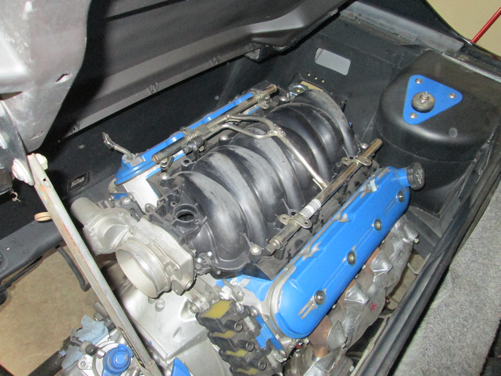
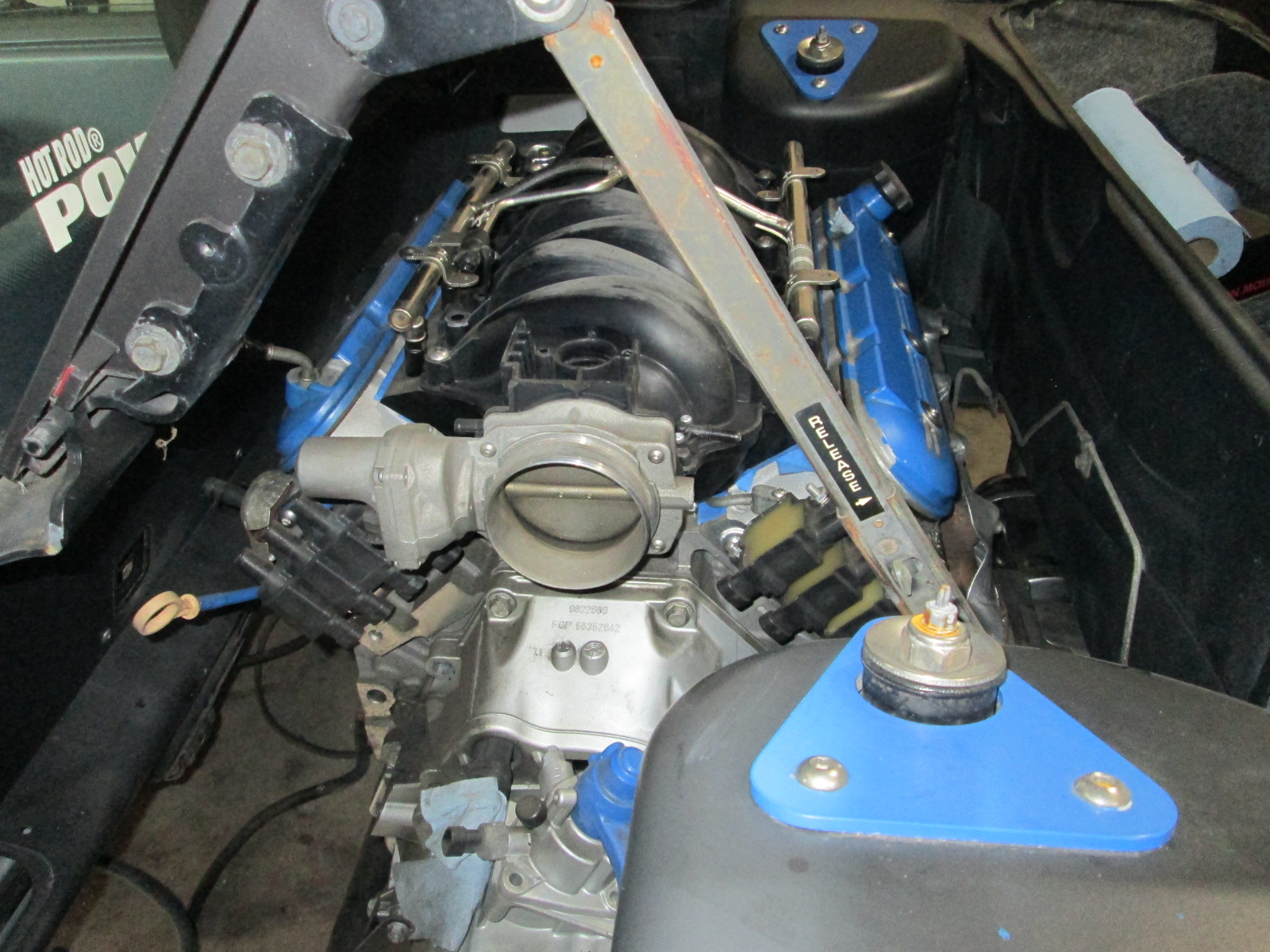
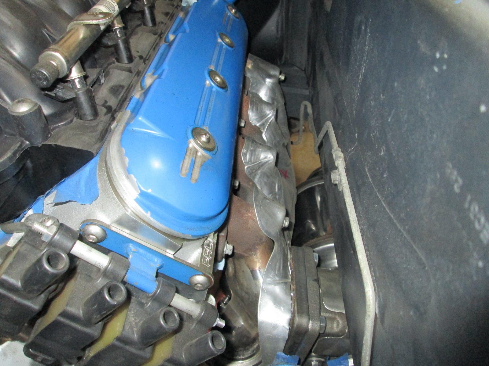
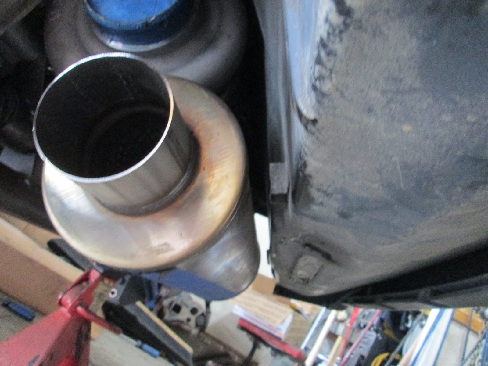
With the engine/cradle back in the Fiero, I can finish up the exhaust to the tips, see if I can use my cutout at the end of a Helmholtz tube, work on the cold side as well as play some more with the rear suspension/knuckles.
Seeing the engine back in the engine bay always helps keep me motivated!
The following 8 users liked this post by fieroguru:
bobcratch (05-03-2021), G Atsma (05-02-2021), jmd (05-03-2021), JoshHefnerX (05-04-2021), Michael Yount (05-02-2021), and 3 others liked this post.
