

88 Fiero Formula LS4/F40 6 speed swap
 12-26-2021 | 01:13 PM
#422

Teching In
Joined: Dec 2021
Posts: 8
Likes: 1
Thanks, Micheal. I'm just trying to solve problems ahead of time. The routing of the exhaust and including the converter around the subframe and the ls4 oil pan with the starter. Also whether or not to have the starter on the oil pan or on the bellhousing is also a thought here. I'm thinking on of holley's performance manifolds 2.56" might work on one side, and an ls7 manifold on the other side going into a y pipe into a 3" pipe might be the way to go here. 3" pipe generally can handle 300 hp, although cam and intake upgrades would make it even more difficult.
Last edited by AspenW41; 12-26-2021 at 01:19 PM.
12-26-2021 | 04:30 PM
#423

Thread Starter

Joined: Feb 2010
Posts: 835
Likes: 221
From: Champaign, IL
Sir,
I am thinking about doing the same thing to a 88 formula. My main question is Were you able to install a cataylic converter on your exhaust setup? I live in Maryland, which is a grandson of California's emmision program. So I am trying to keep any possibly of emmission failure when getting the car tested. As a former emission inspector, I am sure the car's new emmission standard would be the donor car, say a 05 Pontiac GXP.
I am thinking about doing the same thing to a 88 formula. My main question is Were you able to install a cataylic converter on your exhaust setup? I live in Maryland, which is a grandson of California's emmision program. So I am trying to keep any possibly of emmission failure when getting the car tested. As a former emission inspector, I am sure the car's new emmission standard would be the donor car, say a 05 Pontiac GXP.
When the car was Naturally Aspirated, I didn't run any cats, but I have used the same exhaust layout (center dump headers) with cats on a SBC in a Fiero swap.
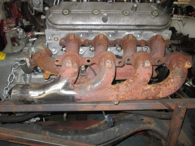
Another option for Naturally Aspirated is to run the exhaust path just like the 2.8 V6 in a Fiero. Use the front LS4 manifold in the front as it already exits pointing at the transmission (similar to stock Fiero). Then modify a truck manifold to do the same on the rear. Use a Y pipe to connect them (like the Fiero 2.8). From there the exhaust is just like Fiero with a cat in front of the engine and muffler in the stock rear location. Here is the stock LS4 front manifold. The one on the bottom had the flange ground down to make it smooth for a V-band.
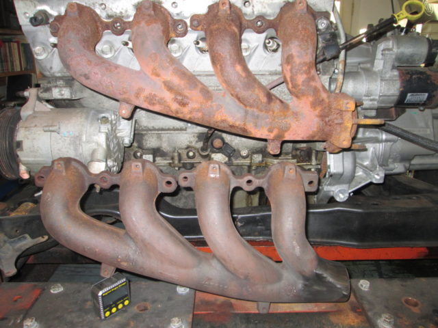
Here is the rear modified truck manifold. The modification was to make it exit horizontal vs at a 45 degree down. The manifold on the engine is the stock LS4 rear manifold.
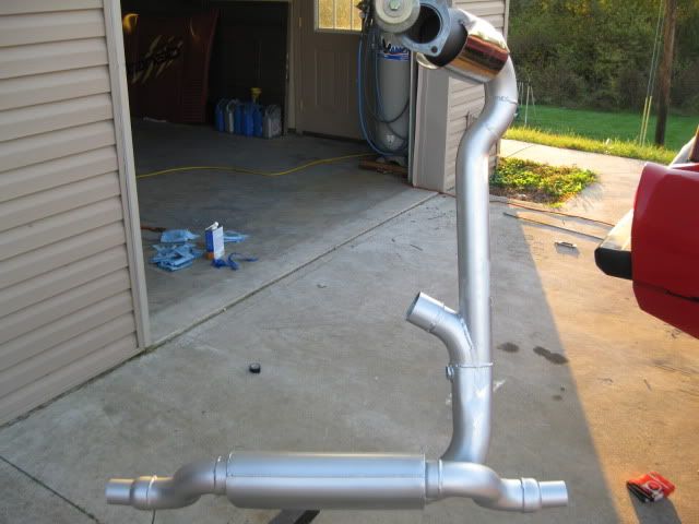
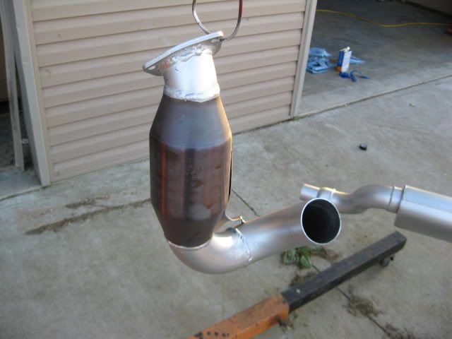
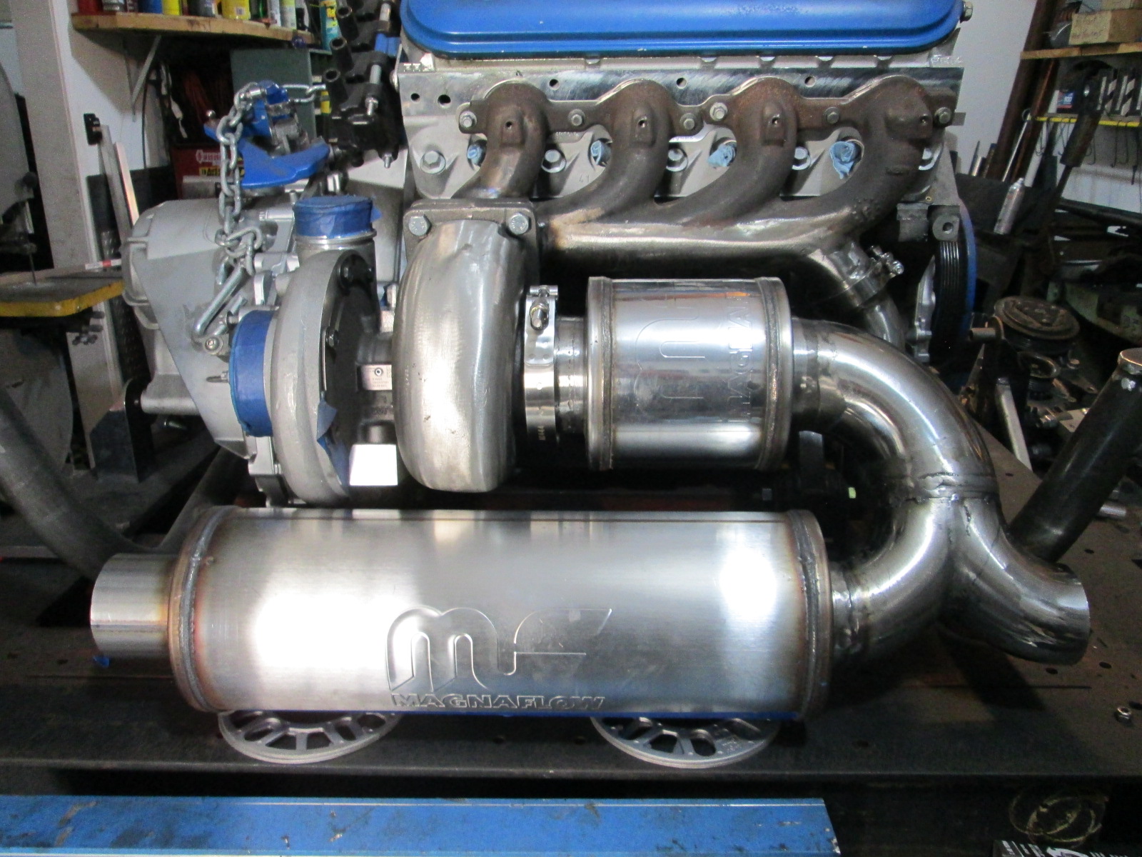
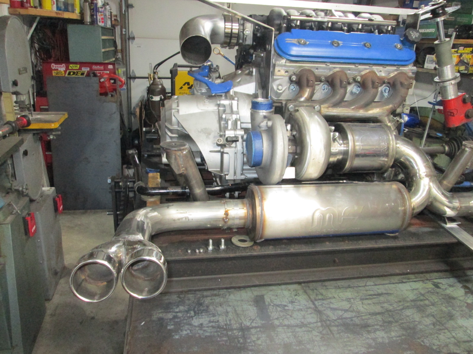
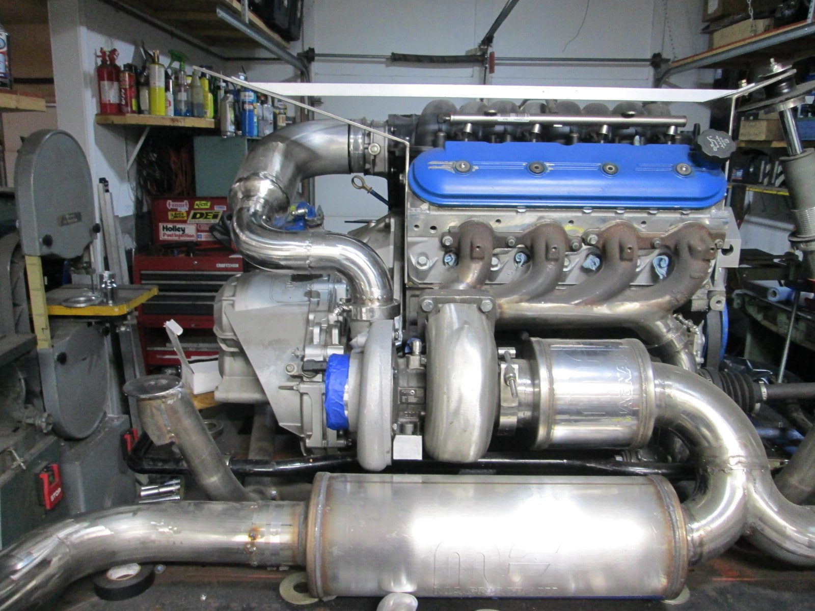
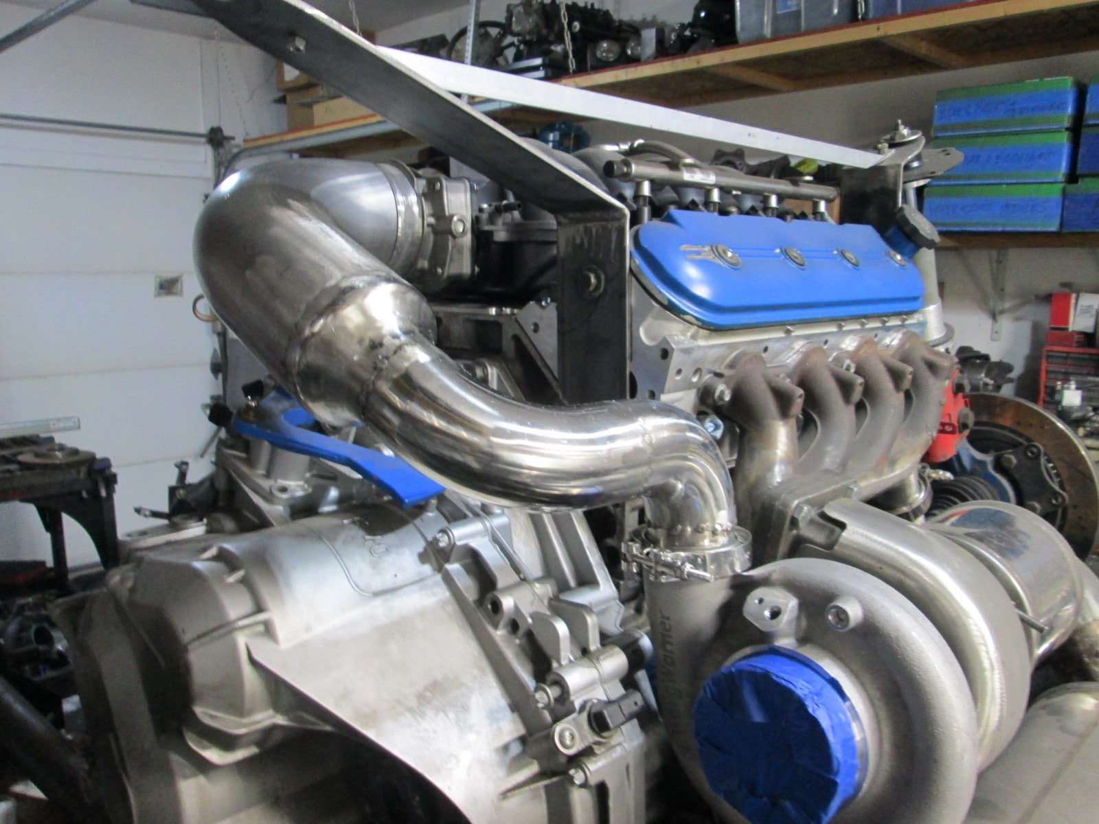
The current turbo exhaust setup (using a custom fabbed rear manifold) has dual inline mufflers. The top 3.5" one could easily be a catalytic converter, if you want it to be.
The following users liked this post:
G Atsma (12-27-2021)
12-29-2021 | 12:12 PM
#425

Joined: Aug 2007
Posts: 2,409
Likes: 107
From: Where the Navy tells me to go
12-29-2021 | 12:19 PM
#426
Teching In
Joined: Dec 2021
Posts: 8
Likes: 1
Thanks for that, AAIIC. I didn't know they had exempted anything before 95". I just ASSumed they were just like Colorado's program where the emmission standard of what the drivetrain came with, is what the car had to have. Then again, we are taking a mid 2000s drivetrain and putting it in a fiero, SO the ls4 emission standard may take precidence here. So just to be safe and responsible, I will have to go with the drivetrains emmission standards.
12-29-2021 | 12:58 PM
#427
Teching In
Joined: Dec 2021
Posts: 8
Likes: 1
just spoke with an emission referee in Mayland. They said because it was an 88 fiero, they would even test it. WOW, AAIIIC. You WERE correct. I had just figured the California's the grandfather of Colorado and Maryland emission program, it would be the same standard.
01-03-2022 | 04:59 PM
#428
Thread Starter
Joined: Feb 2010
Posts: 835
Likes: 221
From: Champaign, IL
I have been slacking on updates...
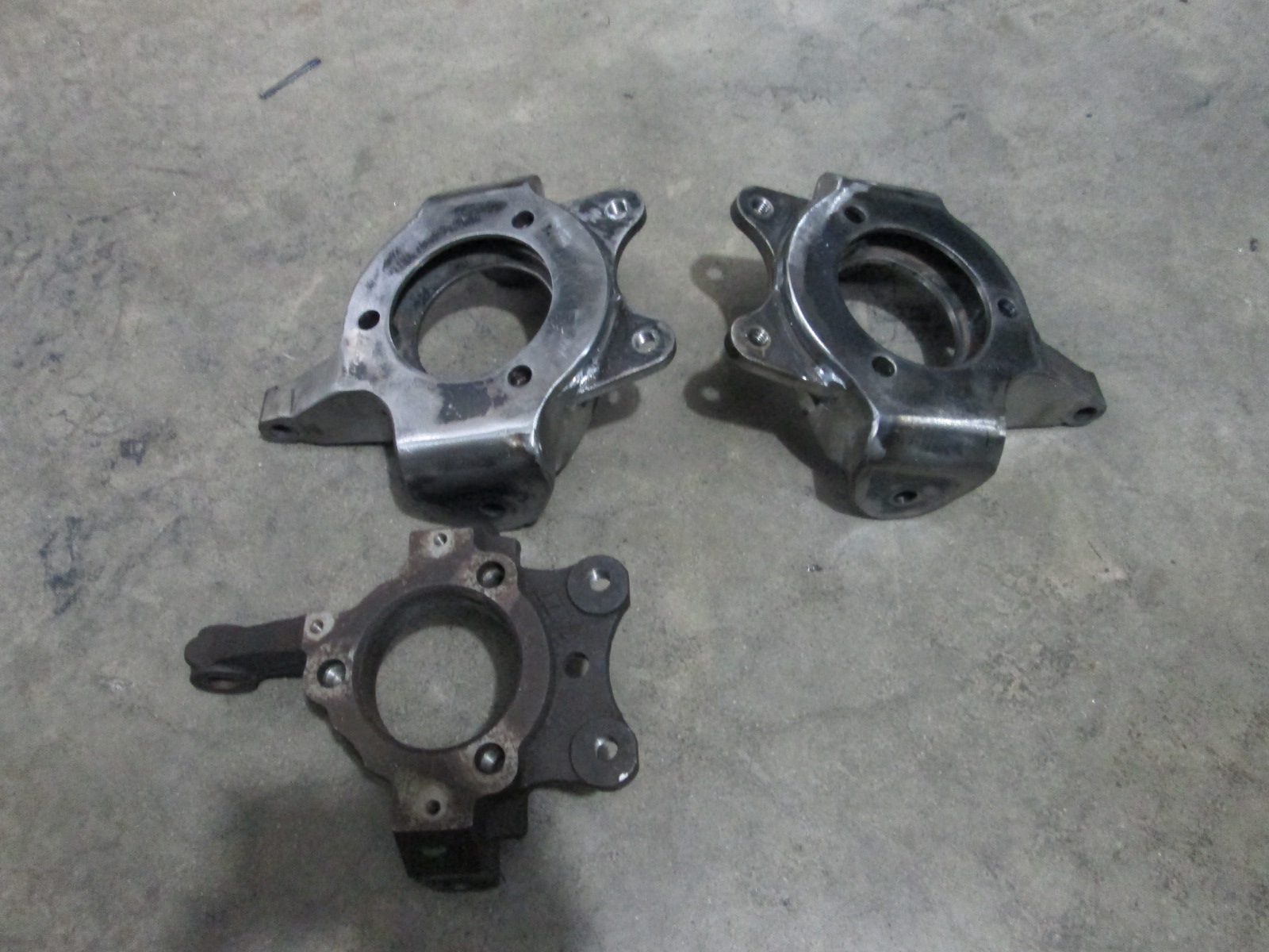
Finished welding up both knuckles:
Finished making the rack spacers. Since the rack had female threads, I found some tie rods with the same female thread pitch, and some 10.8 all thread, then all that was left was machining some hollow alumunum sleeves to dial in 5" of rack movement from lock to lock to match the Fiero rack.
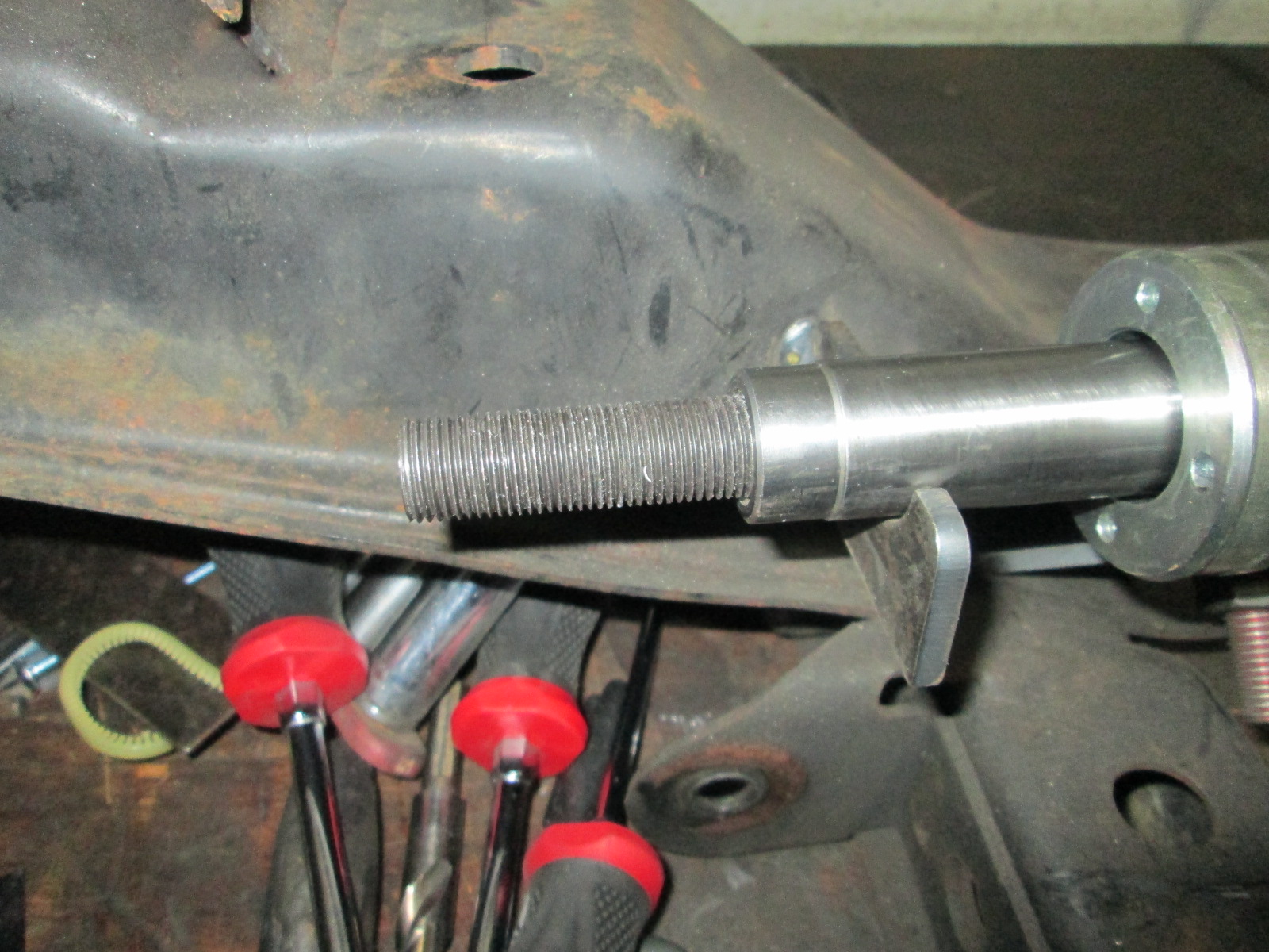
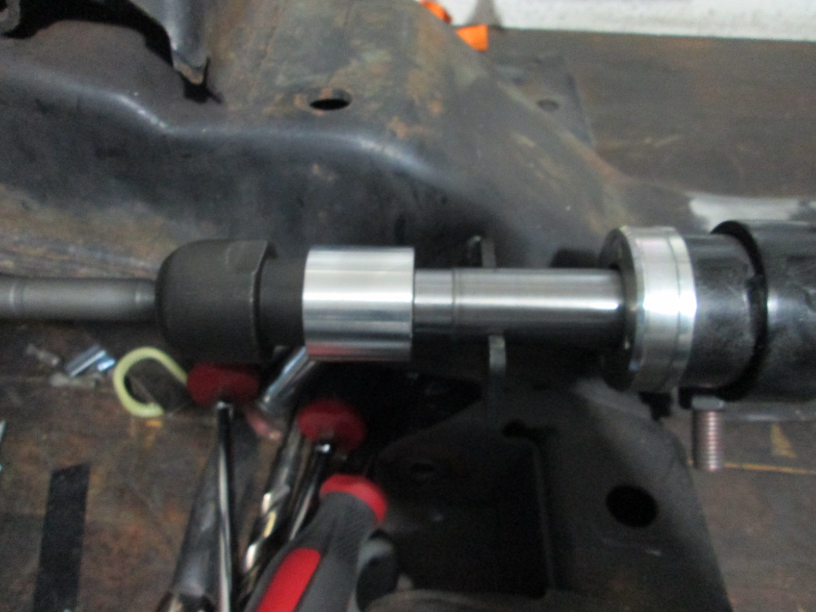
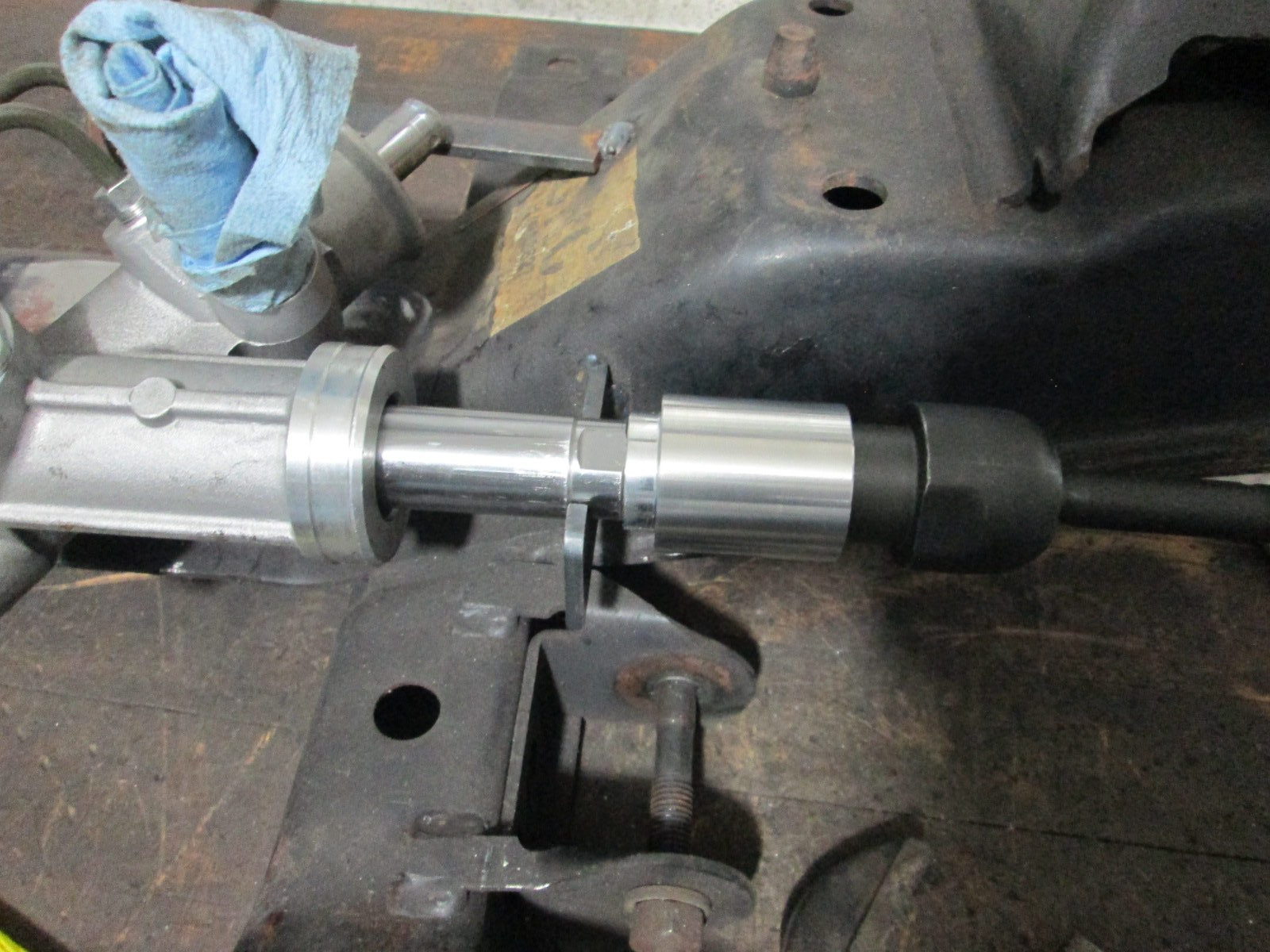
Then reworked the rack brackets out of 1/8" to shed some weight from the earlier 3/16" ones.
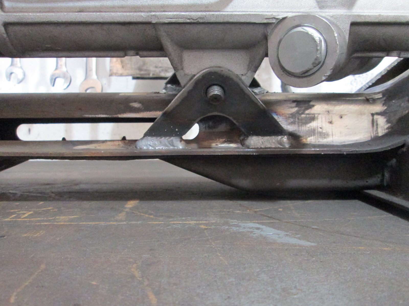
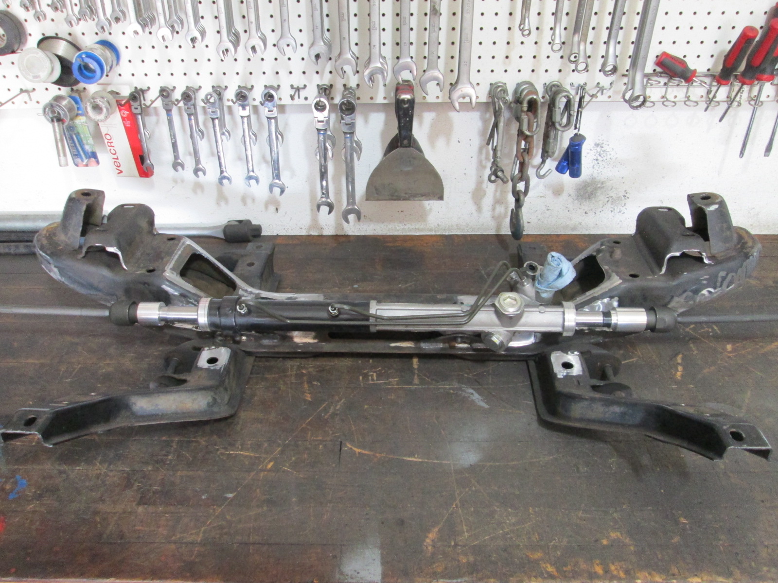
At this time, I tried to buy the Brembo caliper for the other side so I could really finish up the front suspension and ran into supply chain issues. While these are from a car currently in production, there appears to be a shortage of them in stock at the moment.
At this point, I came to my senses and decided to get refocused on getting the car running. The car has a fully functioning front suspension, I doesn't need anything at the moment to work, and I can always swap the front suspension at a later date once the car is running.
Since the drivetrain was in the chasssis, it was a good time to figure out the cold side plumbing. Crude paint rendering:
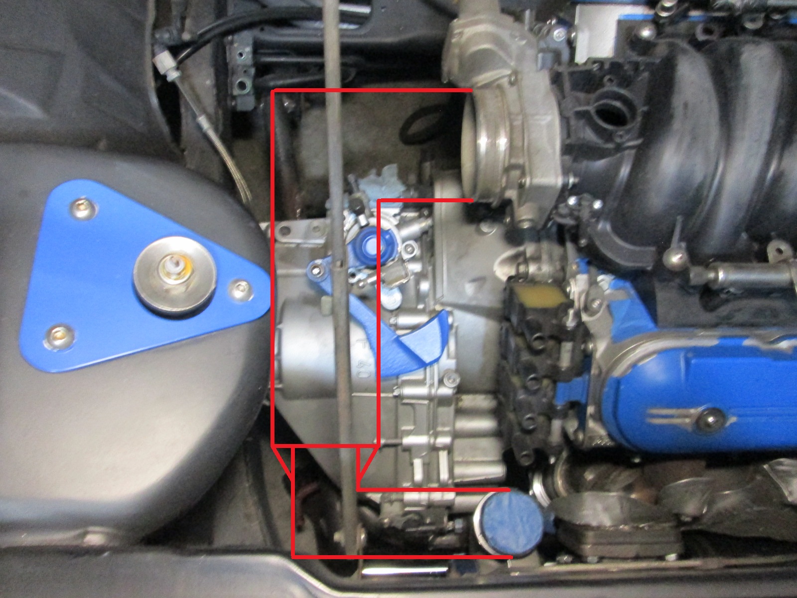
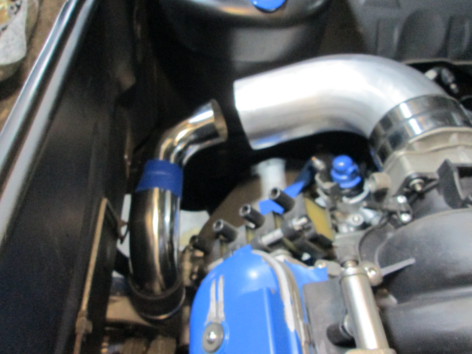
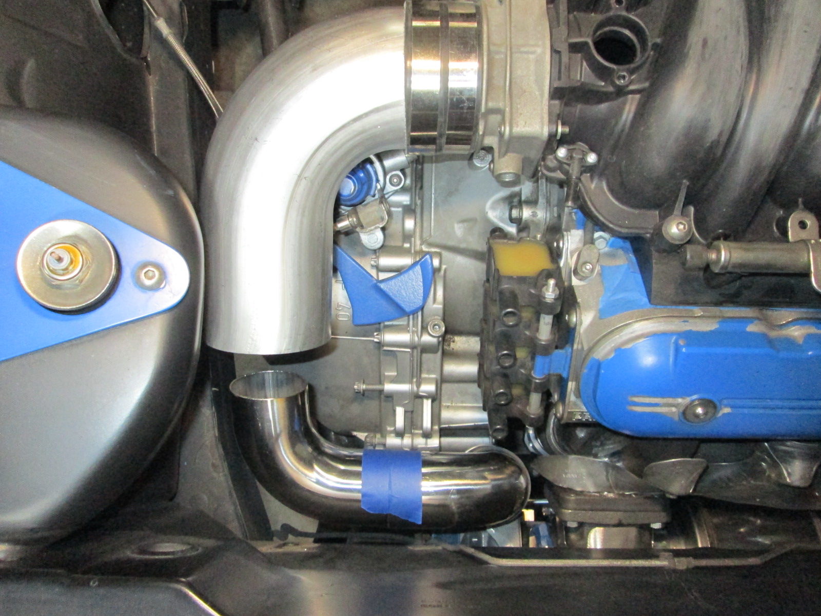
Mocking up the tubing. With the 4" tube now clamped in place and clearing the strut tower, the rest can be fabbed up on the bench:
Also worked some more on the exhaust... When the car had the 3.55 final drive, it didn't have any noticeable resonance when cruising in 6th at 70 mph. When I swapped to the 3.091 final drive, the car was noticeably louder at 70 mph due to resonance and it dropped off as the car got to 80 mph. Since i am going with 3" exhaust, resonance will be worse, so I want to use a helmholtz 1/4 wavelength resonator and have used my prior observations of resonance rpm to help narrow down the expected length needed.
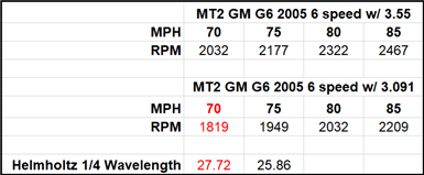
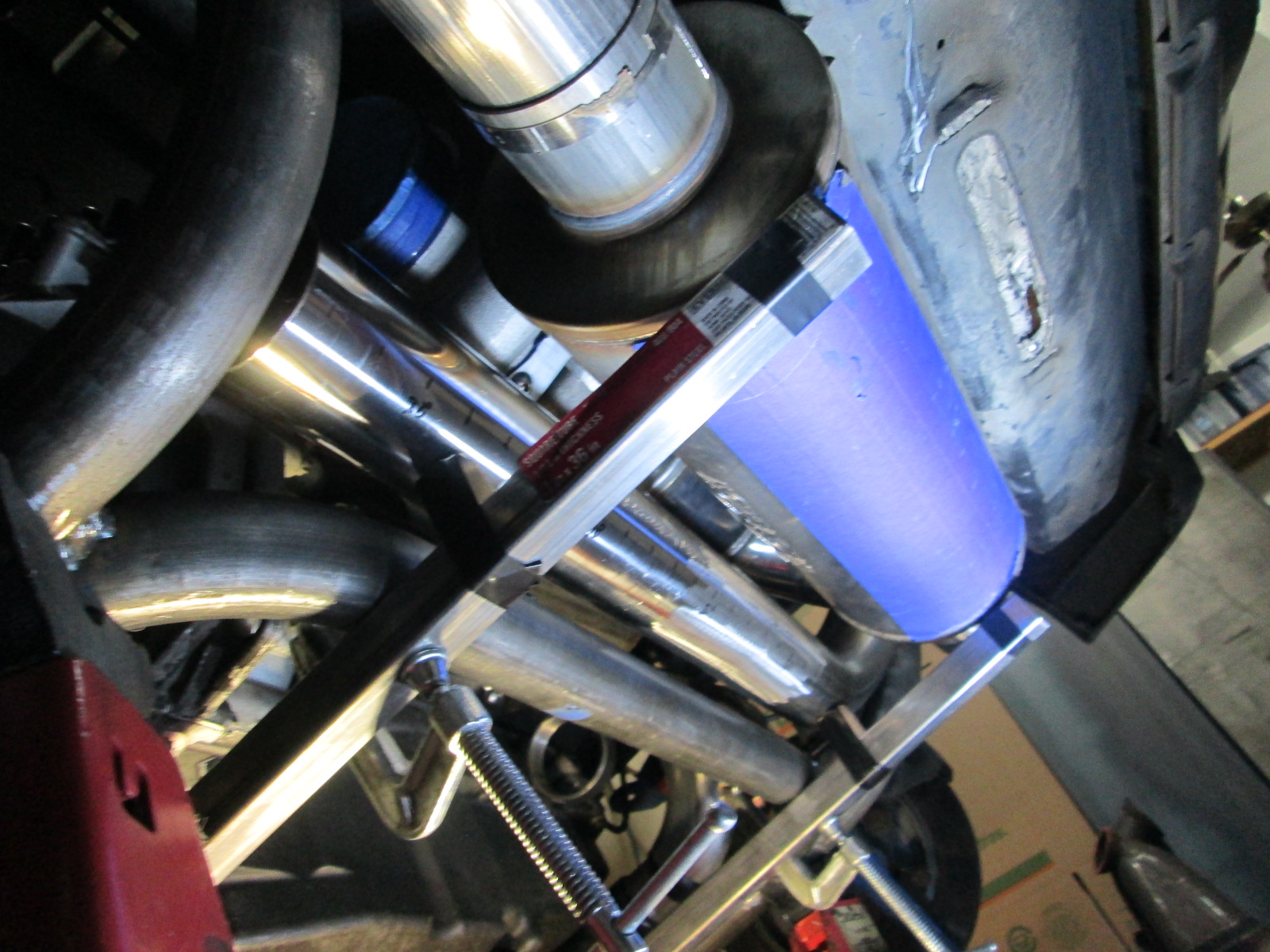
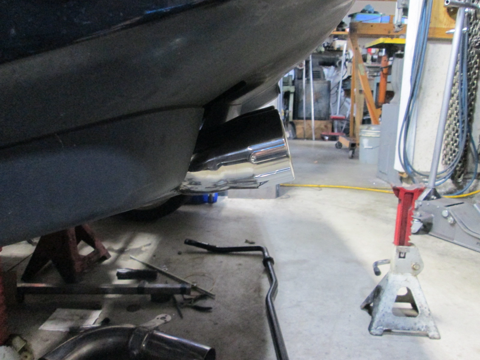
I had talked about using the cutout on the passenger exhaust tube to act as a resonator, but there is just too much pipe to fit in that area. Instead, I will route it parallel to the muffler between the muffler and cradle rail. Here it is setting in place. It is about 27 3/8" in length, which should work. It will come off the exhaust at the Y section where the 3.5" splits to dual 3" exhaust tubes.
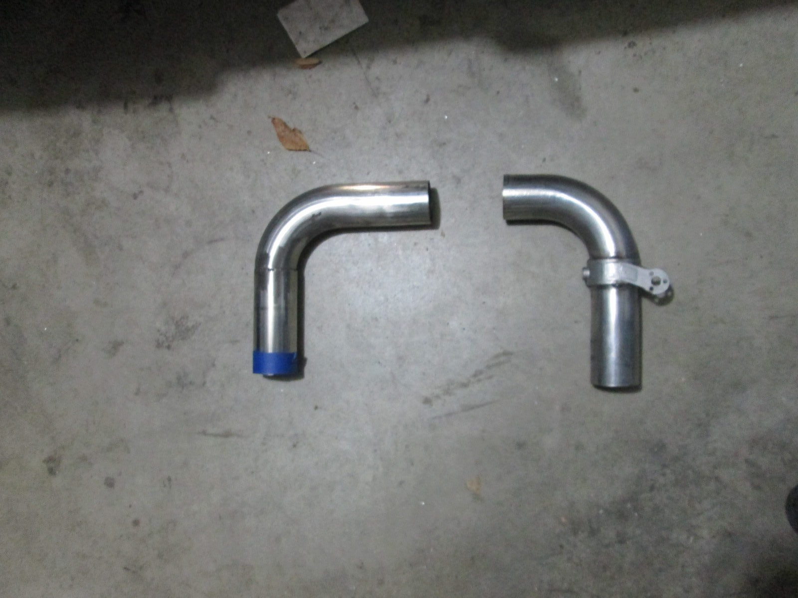
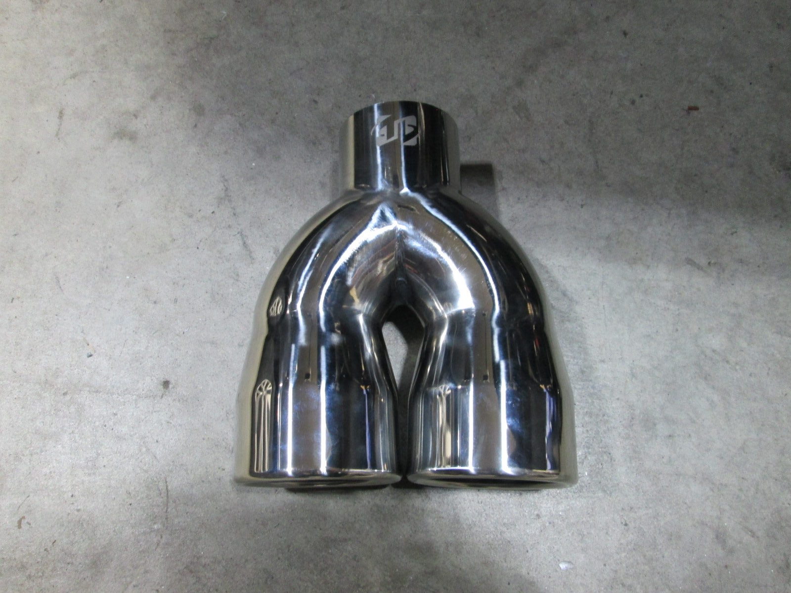
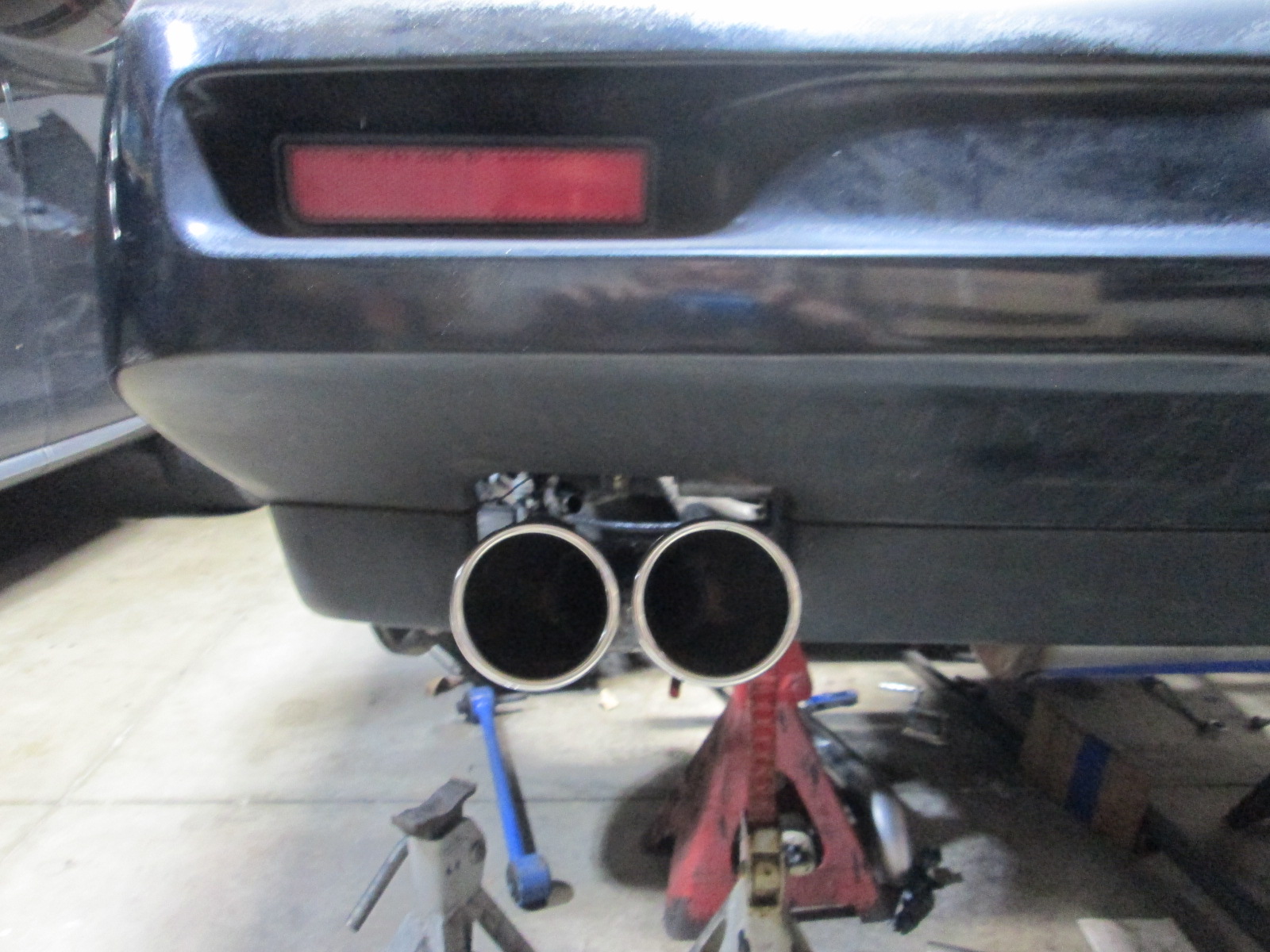
Then moved on to fabbing up the exhaust tips:
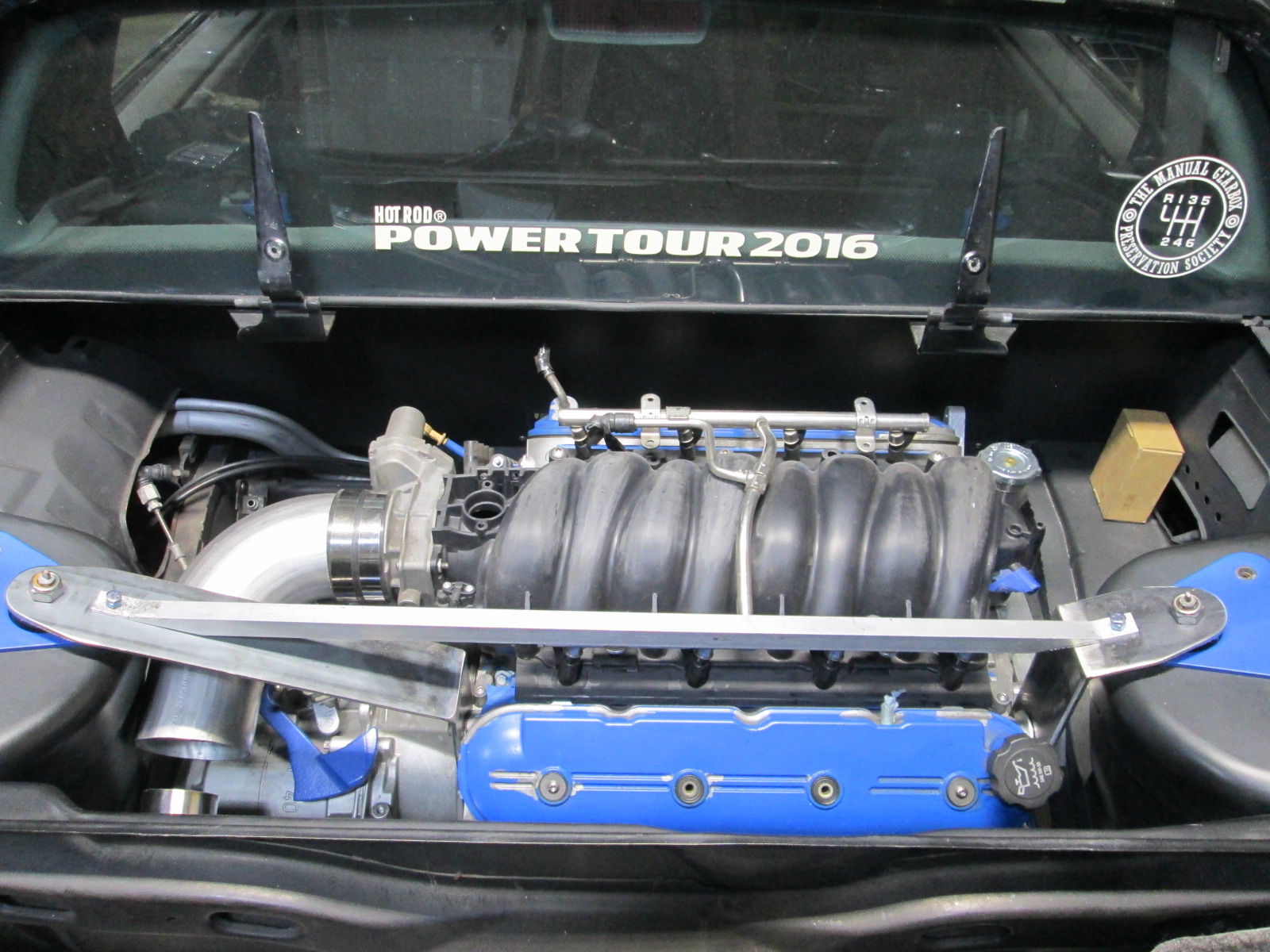
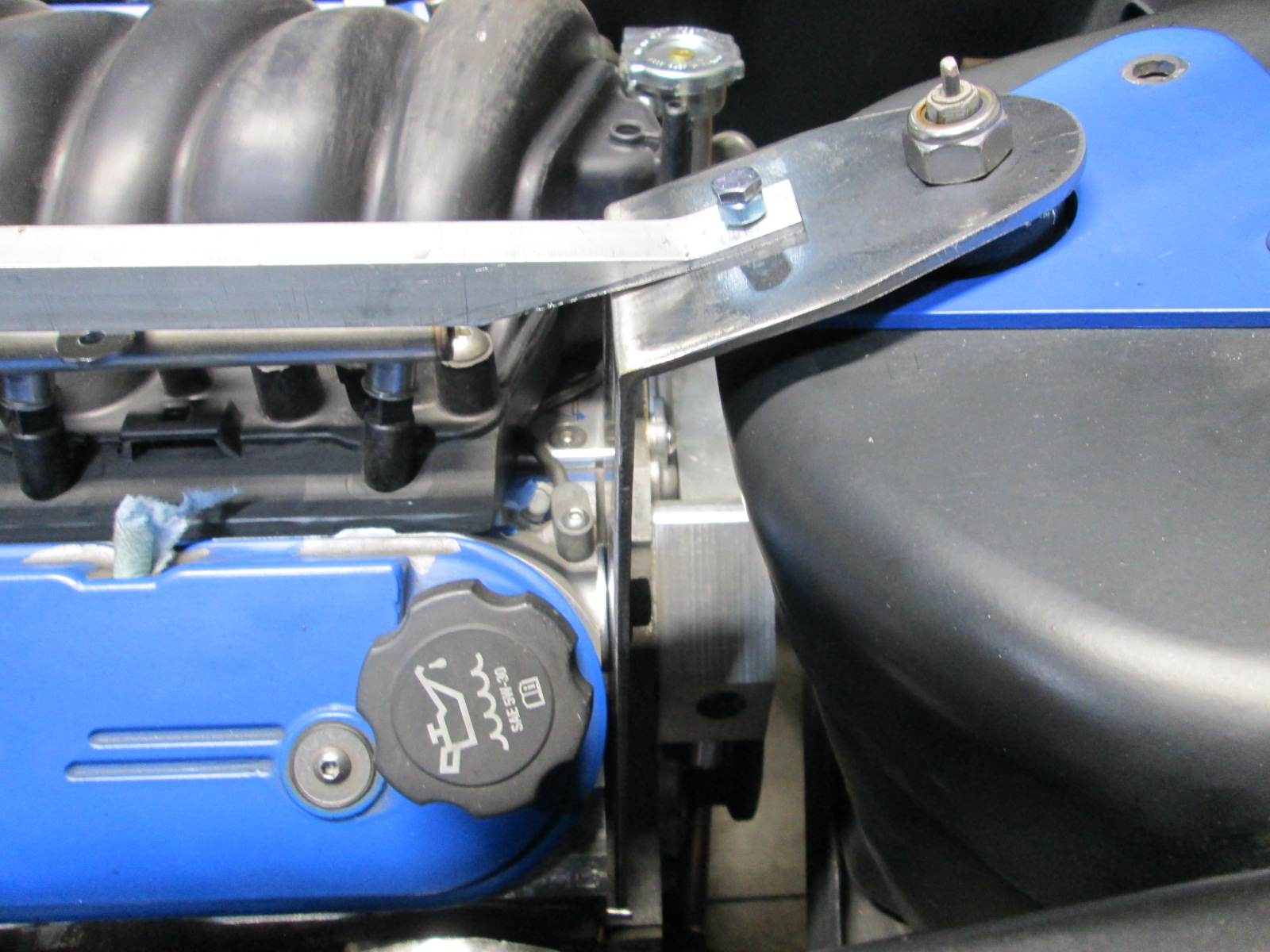
One last thing before pulling the drivetrain for more bench work, was to locate the top of the struts so I could find a good home for the sway bar.
Then everything went back to the bench.
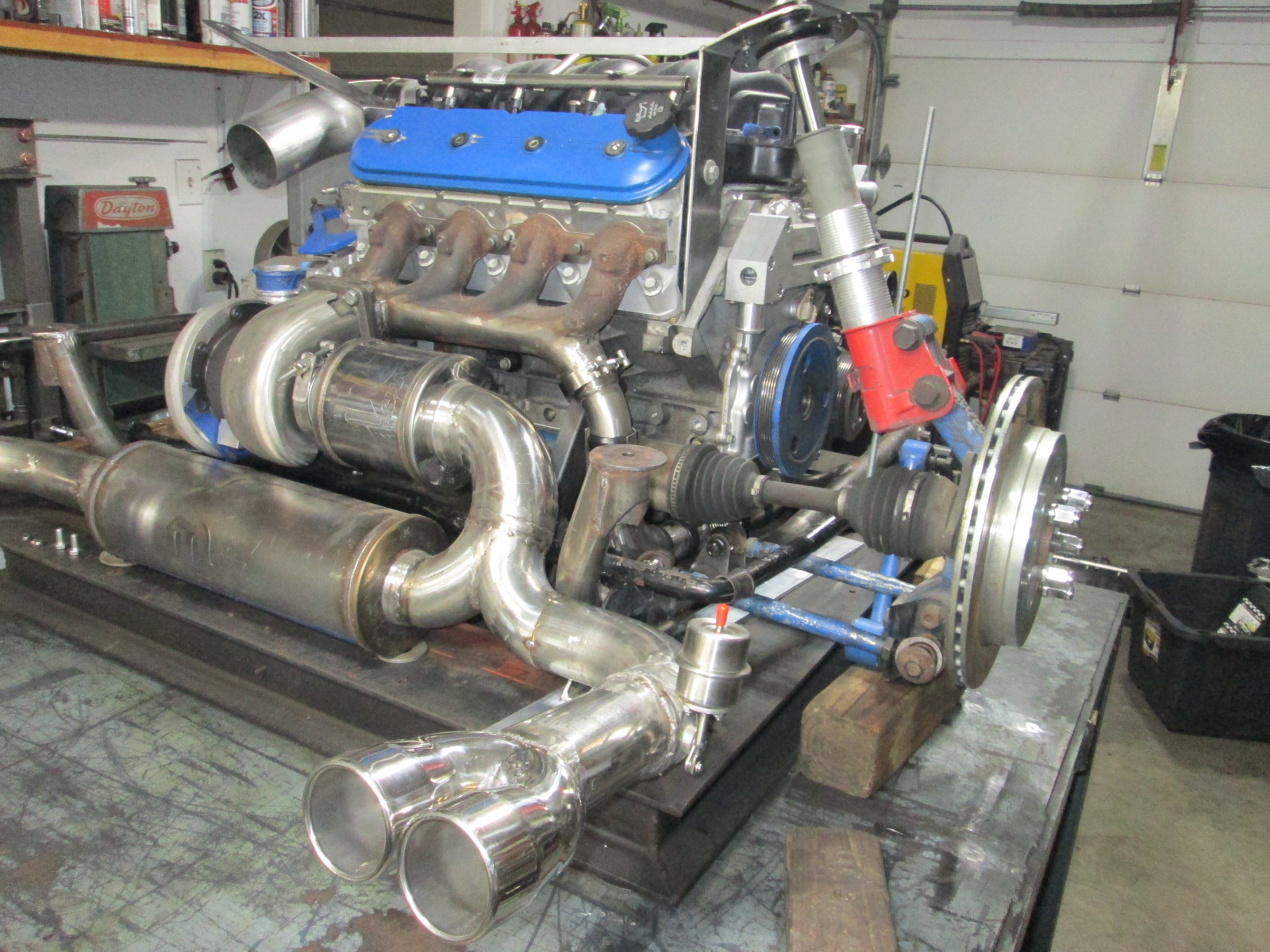
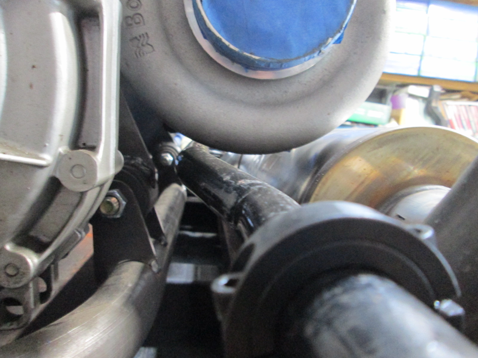
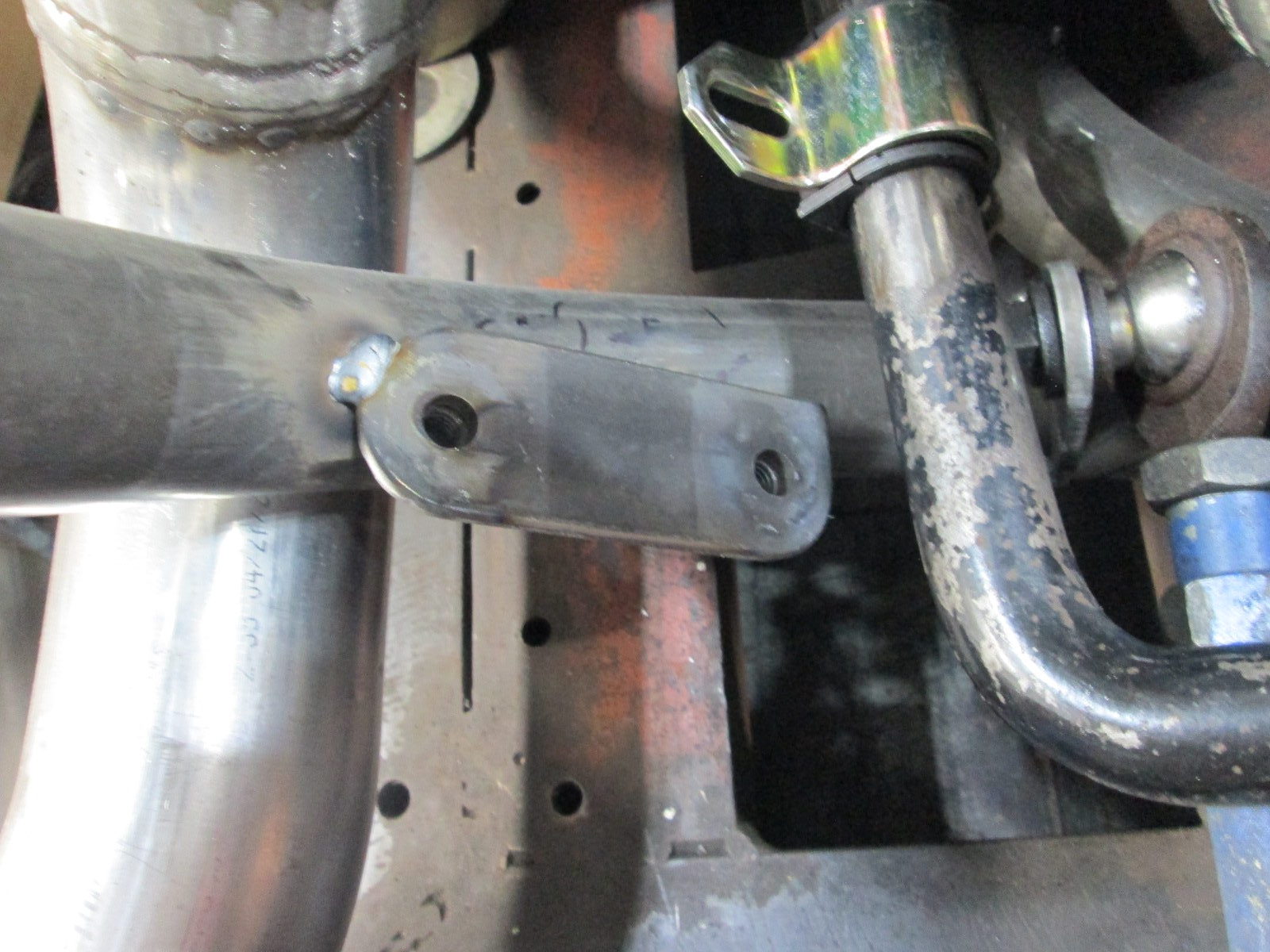
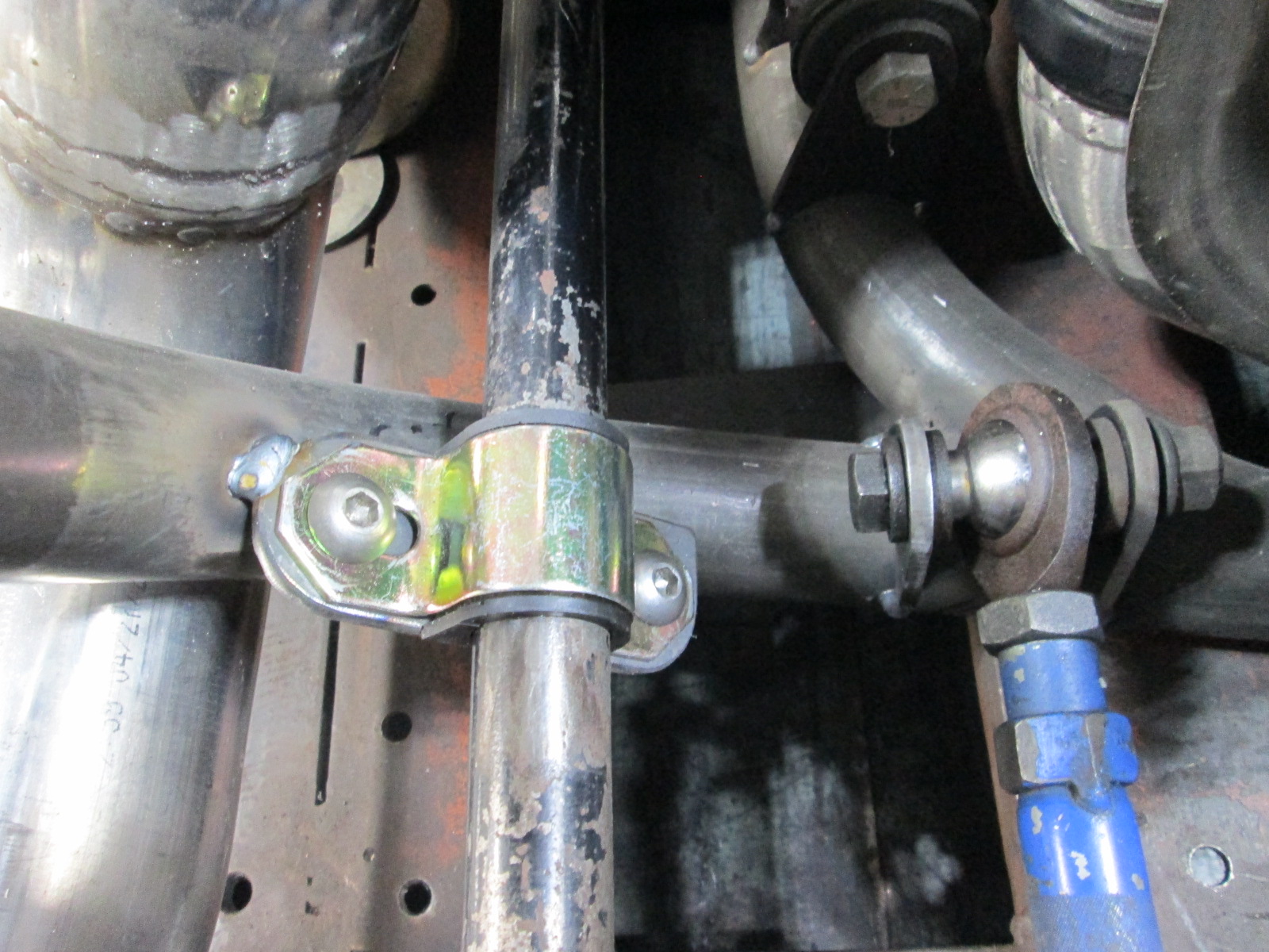
Then the sway bar mock up. The turbo forces the sway bar to be several inches lower than stock, which means it can't go over the axle any more. I ended up having to flip it over and run it below the axle and above the lateral links. Here is a stand to help dial in the location and will eventually hold the bar in place while I fabricate the sway bar brackets to the tubular cradle.
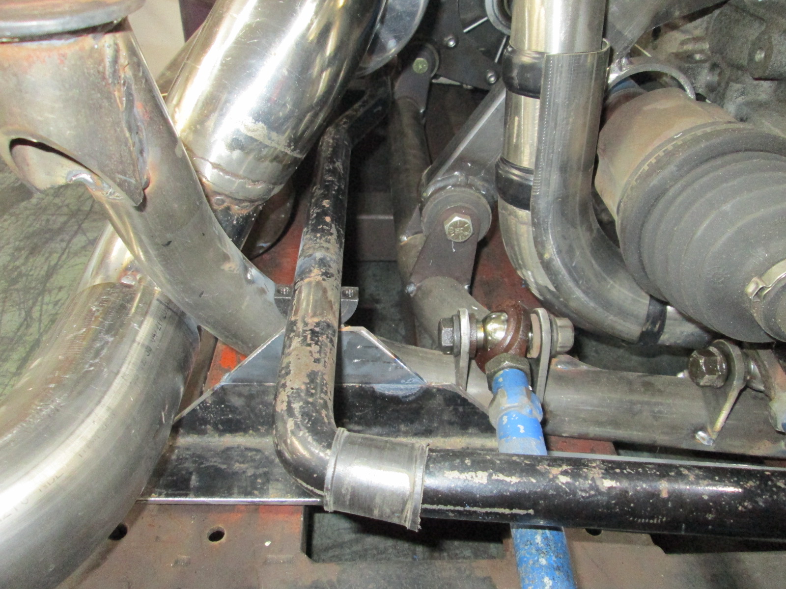
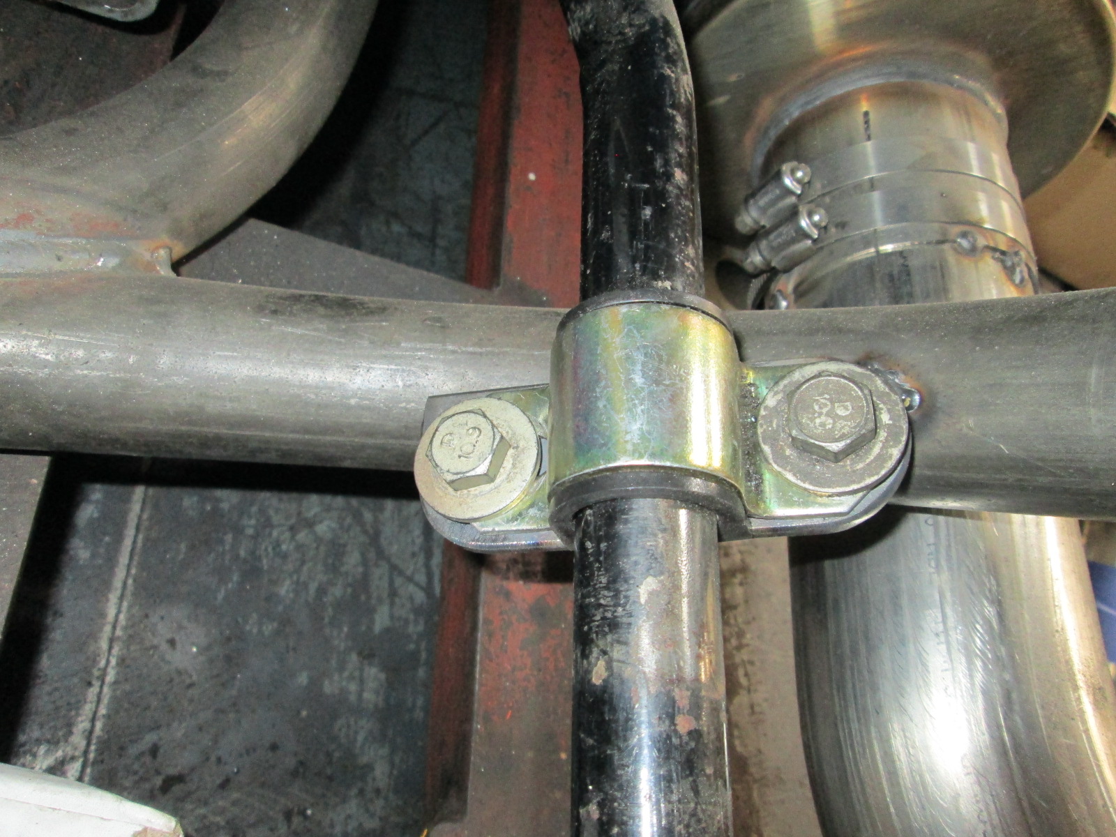
Full compression (also clears at full droop).
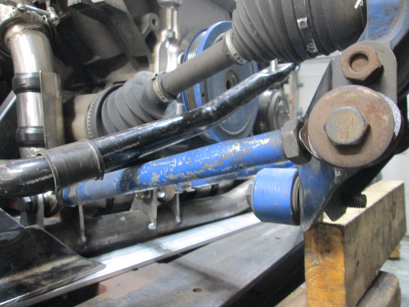
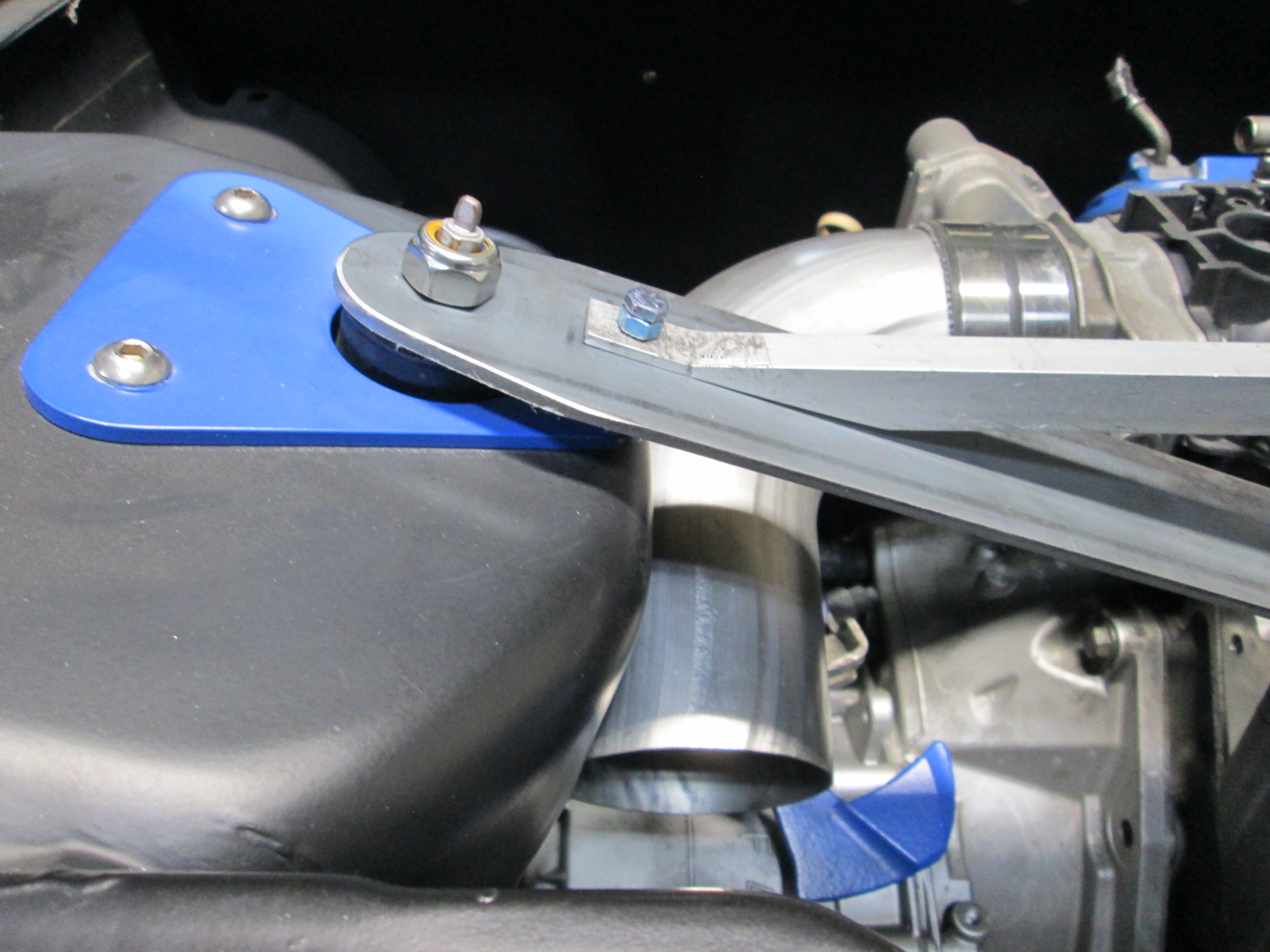
Clearance of the sway bar to the compressor housing:
Finished welding up both knuckles:
Finished making the rack spacers. Since the rack had female threads, I found some tie rods with the same female thread pitch, and some 10.8 all thread, then all that was left was machining some hollow alumunum sleeves to dial in 5" of rack movement from lock to lock to match the Fiero rack.
Then reworked the rack brackets out of 1/8" to shed some weight from the earlier 3/16" ones.
At this time, I tried to buy the Brembo caliper for the other side so I could really finish up the front suspension and ran into supply chain issues. While these are from a car currently in production, there appears to be a shortage of them in stock at the moment.
At this point, I came to my senses and decided to get refocused on getting the car running. The car has a fully functioning front suspension, I doesn't need anything at the moment to work, and I can always swap the front suspension at a later date once the car is running.
Since the drivetrain was in the chasssis, it was a good time to figure out the cold side plumbing. Crude paint rendering:
Mocking up the tubing. With the 4" tube now clamped in place and clearing the strut tower, the rest can be fabbed up on the bench:
Also worked some more on the exhaust... When the car had the 3.55 final drive, it didn't have any noticeable resonance when cruising in 6th at 70 mph. When I swapped to the 3.091 final drive, the car was noticeably louder at 70 mph due to resonance and it dropped off as the car got to 80 mph. Since i am going with 3" exhaust, resonance will be worse, so I want to use a helmholtz 1/4 wavelength resonator and have used my prior observations of resonance rpm to help narrow down the expected length needed.
I had talked about using the cutout on the passenger exhaust tube to act as a resonator, but there is just too much pipe to fit in that area. Instead, I will route it parallel to the muffler between the muffler and cradle rail. Here it is setting in place. It is about 27 3/8" in length, which should work. It will come off the exhaust at the Y section where the 3.5" splits to dual 3" exhaust tubes.
Then moved on to fabbing up the exhaust tips:
One last thing before pulling the drivetrain for more bench work, was to locate the top of the struts so I could find a good home for the sway bar.
Then everything went back to the bench.
Then the sway bar mock up. The turbo forces the sway bar to be several inches lower than stock, which means it can't go over the axle any more. I ended up having to flip it over and run it below the axle and above the lateral links. Here is a stand to help dial in the location and will eventually hold the bar in place while I fabricate the sway bar brackets to the tubular cradle.
Full compression (also clears at full droop).
Clearance of the sway bar to the compressor housing:
01-03-2022 | 05:10 PM
#430
Teching In
Joined: Dec 2021
Posts: 8
Likes: 1
I'm curious what power steering rack you went with on this build. I do remember a build on Fiero.nl using a Corvette Remanufactured ZR1 steering rack being also dead on, that only needed some fabbed up brackets on one side of the rack, because it was pretty much a dead on swap. There was a a build that did use a Camaro/Firebird steering rack as well, that needed a litte more fabing help to work. I'm sure your arms will thank you when your go to parallel park.
01-03-2022 | 06:32 PM
#431
Thread Starter
Joined: Feb 2010
Posts: 835
Likes: 221
From: Champaign, IL
I'm curious what power steering rack you went with on this build. I do remember a build on Fiero.nl using a Corvette Remanufactured ZR1 steering rack being also dead on, that only needed some fabbed up brackets on one side of the rack, because it was pretty much a dead on swap. There was a a build that did use a Camaro/Firebird steering rack as well, that needed a litte more fabing help to work. I'm sure your arms will thank you when your go to parallel park.
The following users liked this post:
G Atsma (01-03-2022)

The following 2 users liked this post by ryeguy2006a:
AspenW41 (01-04-2022), Ls7colorado (04-18-2022)
01-04-2022 | 07:22 PM
#434
Thread Starter
Joined: Feb 2010
Posts: 835
Likes: 221
From: Champaign, IL
4th gen.
The following users liked this post:
AspenW41 (01-04-2022)
04-17-2022 | 05:28 PM
#435
Thread Starter
Joined: Feb 2010
Posts: 835
Likes: 221
From: Champaign, IL
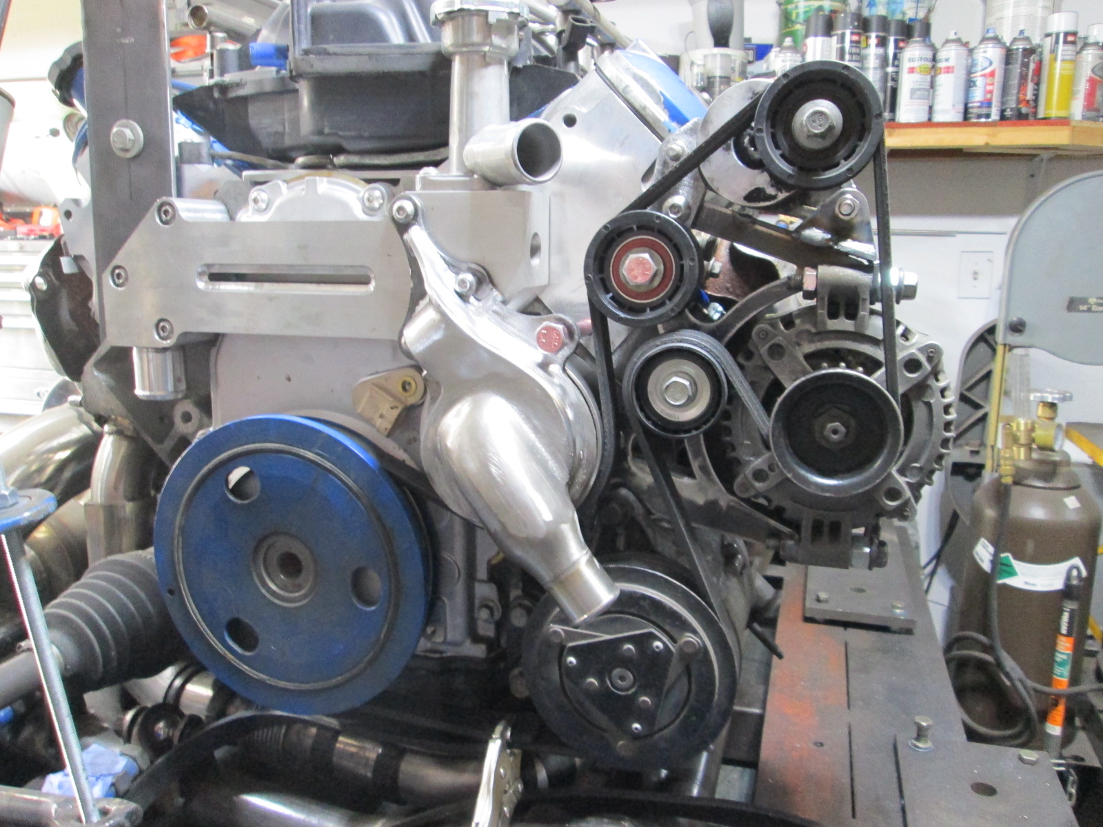
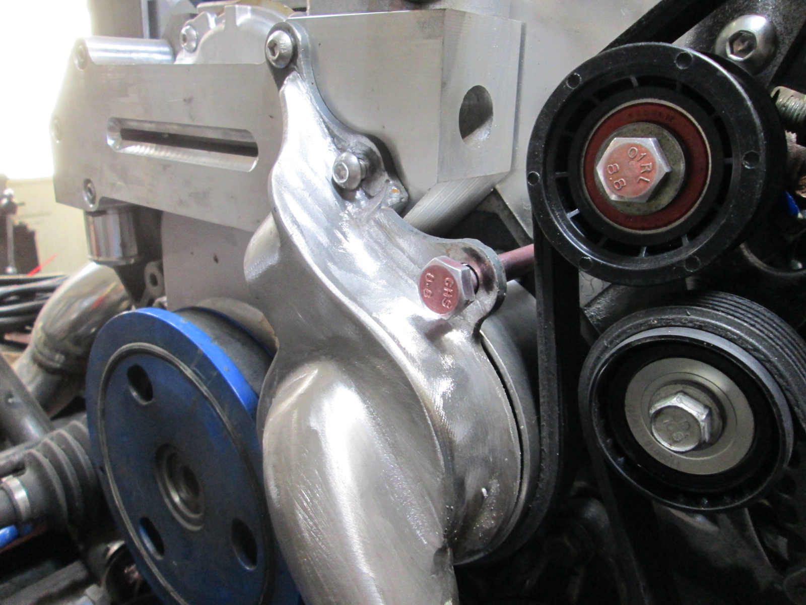
I finally figured it out and fabricated a workable mechanical water pump solution! It uses a $50 water pump insert (pulley flange, shaft, seals, bearings, and impeller), I just had to make the housing for it, and rework all the alternator, AC, and tensioner brackets.
The following 2 users liked this post by fieroguru:
Ls7colorado (04-18-2022), NSFW (04-17-2022)

The following users liked this post:
G Atsma (04-17-2022)


The following 2 users liked this post by G Atsma:
Jimbo1367 (04-26-2022), Ls7colorado (04-18-2022)
05-01-2022 | 03:52 PM
#440
Thread Starter
Joined: Feb 2010
Posts: 835
Likes: 221
From: Champaign, IL
Thanks guys!
Fabbed up the sway bar mounts:
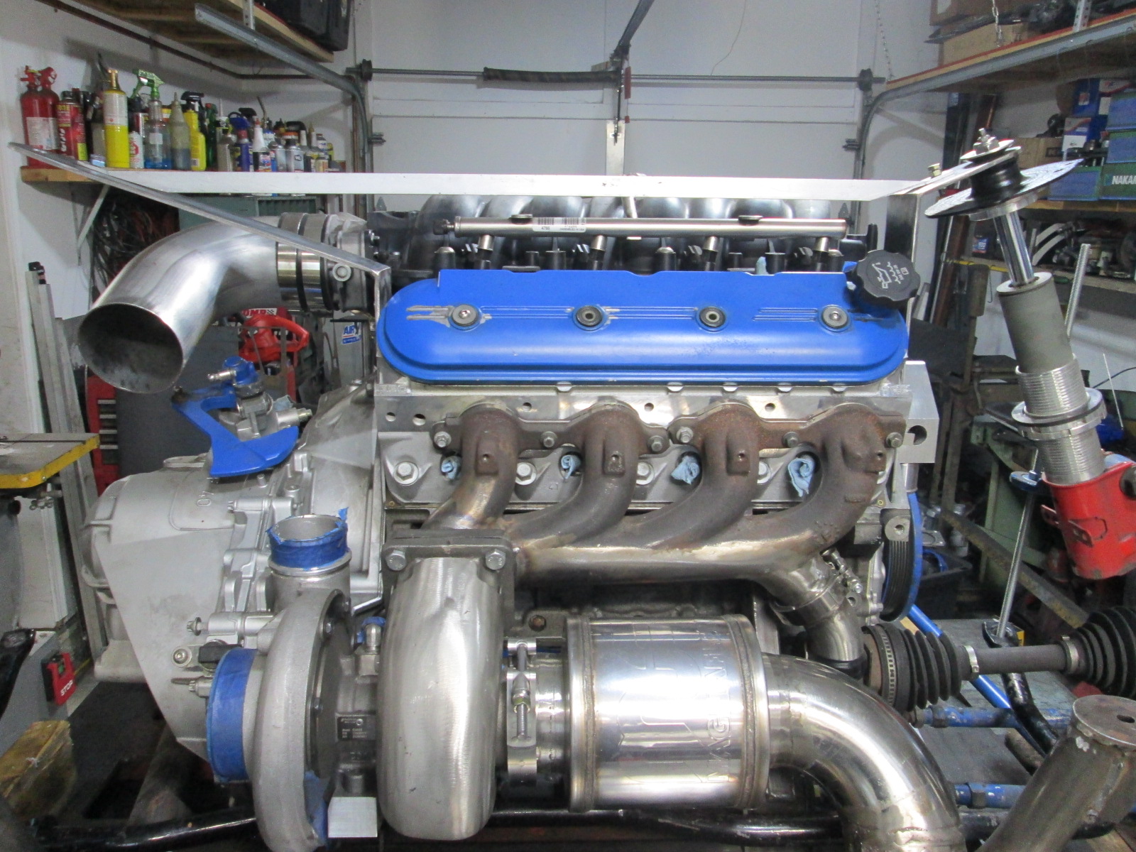
The 369SXE is said to be better suited for small cube, high boost applications. General internet theory is that it is due to the much smaller gap in the housing for the air off the wheel to exit.
The gap is quite small being 0.225 to 0.25" and the older versions were about twice as large from other pictures.
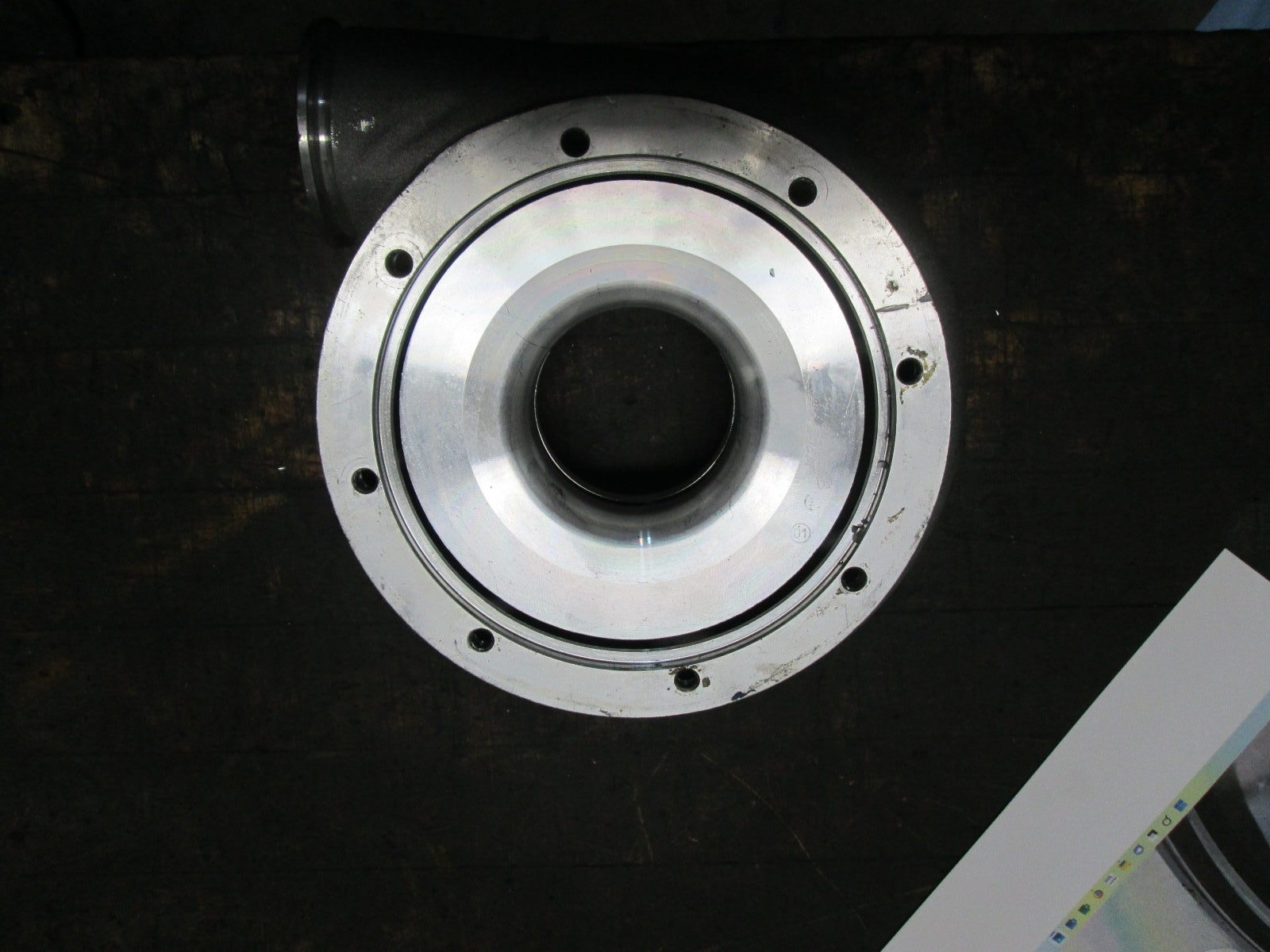
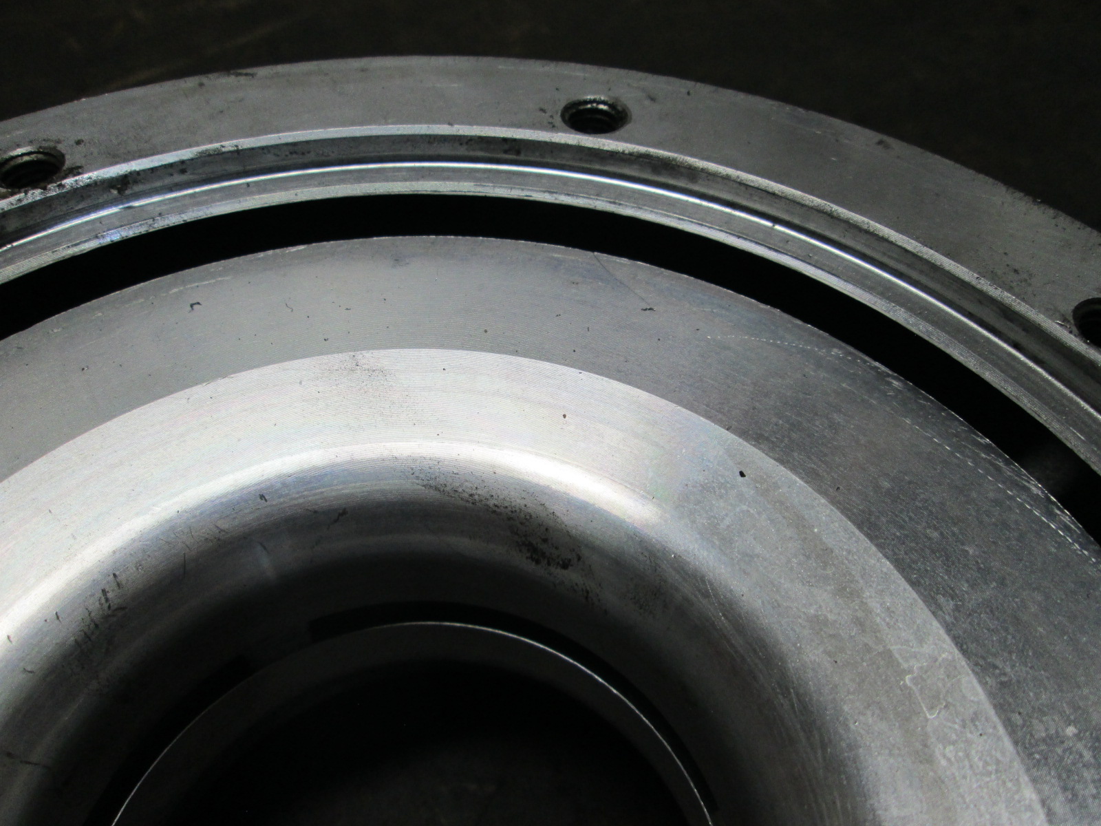
So while everyone thinks the main issue with the 369sxe is the gap, I haven't ever seen someone try to modify it. So why not... went ahead and opened that section of the compressor housing up to .350".
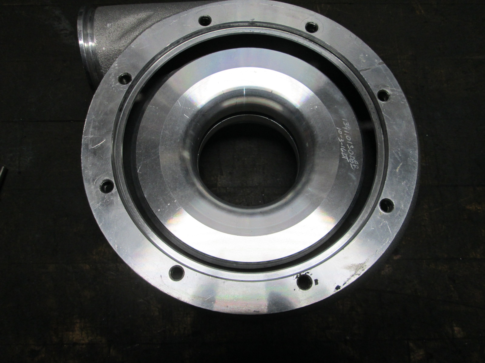
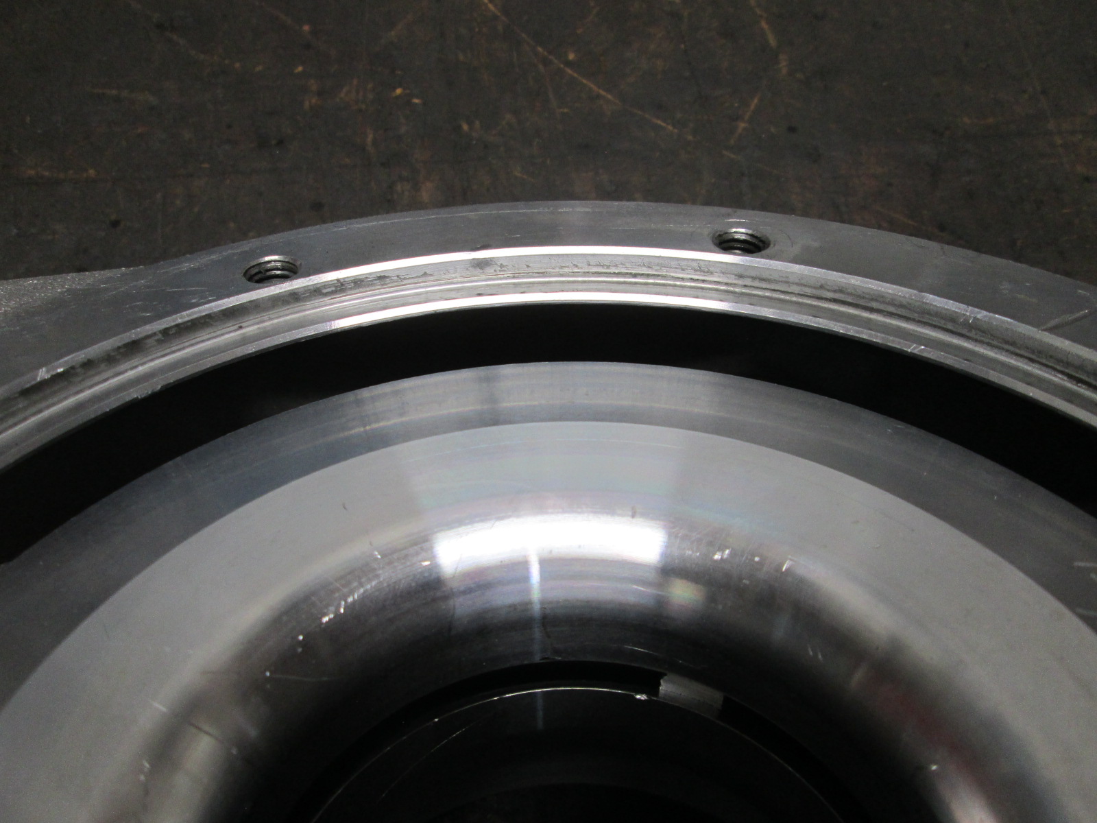
The cover also had the hose barb outlet section cut off and machined flat with a pilot bore to accept a V-band:
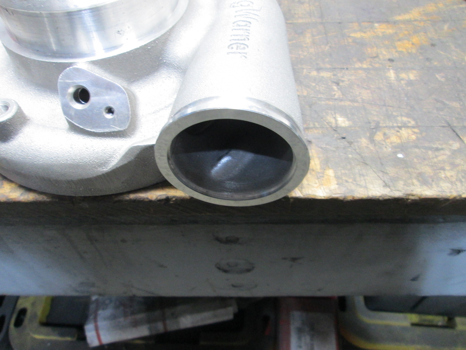
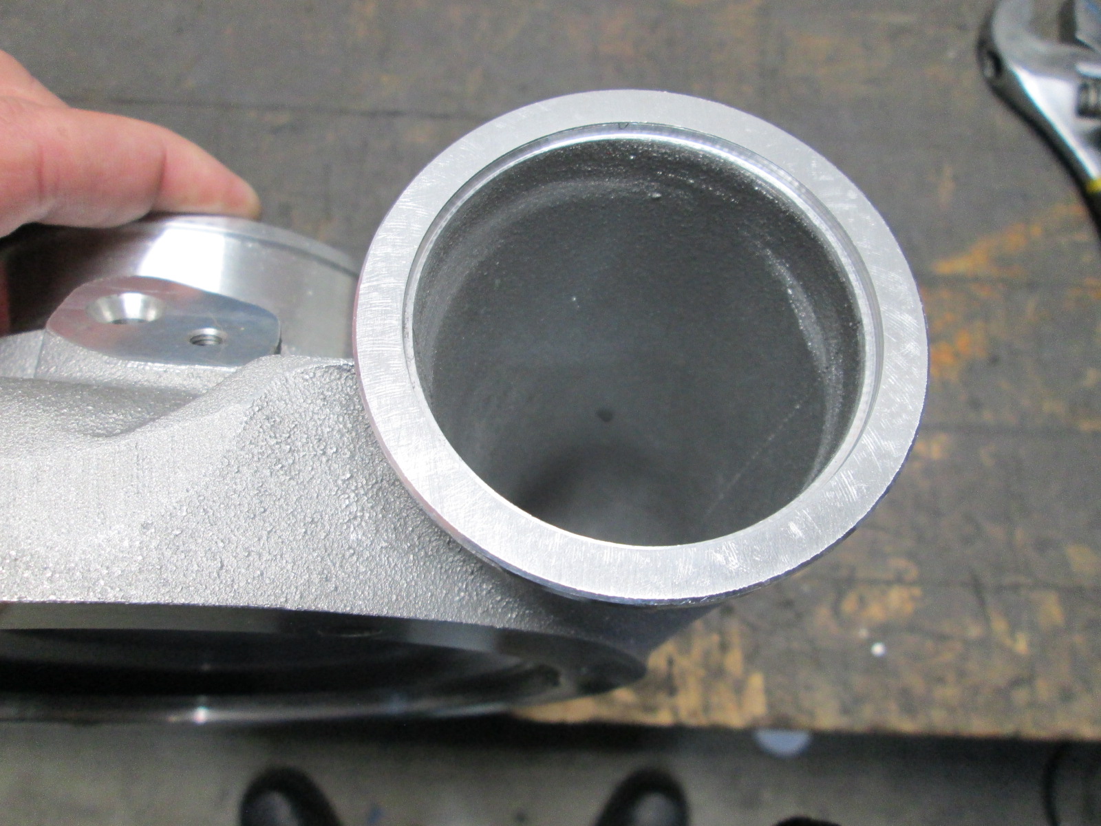
Last thing I did this weekend was tack together the cold (non-I/C = warm) side. V-band off the compressor, silicone coupler at the TB. There is a honeycomb airflow straightener about 1.5" after the diameter transition. The LS7 MAF will be after it and before the bend.
Fabbed up the sway bar mounts:
The 369SXE is said to be better suited for small cube, high boost applications. General internet theory is that it is due to the much smaller gap in the housing for the air off the wheel to exit.
The gap is quite small being 0.225 to 0.25" and the older versions were about twice as large from other pictures.
So while everyone thinks the main issue with the 369sxe is the gap, I haven't ever seen someone try to modify it. So why not... went ahead and opened that section of the compressor housing up to .350".
The cover also had the hose barb outlet section cut off and machined flat with a pilot bore to accept a V-band:
Last thing I did this weekend was tack together the cold (non-I/C = warm) side. V-band off the compressor, silicone coupler at the TB. There is a honeycomb airflow straightener about 1.5" after the diameter transition. The LS7 MAF will be after it and before the bend.
Last edited by fieroguru; 05-01-2022 at 05:00 PM.