


Cooling fans and A/C compressor wiring
First off, I am a wiring idiot and it's nothing short of a miracle I've gotten this far with the wiring, so bear with me.
I've got an LS1 in a 56 chevy with dual cooling fans and factory LS1 compressor with a vintage air a/c system. The fans and compressor wiring are shown in the attached diagram.
The fans kick on when the engine reaches a certain temp, but the fans do not kick on with the a/c compressor since the a/c request signal wire was left out of the PCM harness.
I am looking for the simplest solution for getting the fan(s) to kick on when the compressor kicks on.
Can I just splice into the existing wiring; i.e., splice from the 'A/C compressor clutch B+ supply' to the 'DK Blue CKT 473 wire'...or something else?
If my only option is to add the a/c request signal wire to PCM, then I'll go that route, but would prefer not to as the PCM is under the console and a ROYAL pain to get to...last resort!

Thanks in advance for all your input!
I've got an LS1 in a 56 chevy with dual cooling fans and factory LS1 compressor with a vintage air a/c system. The fans and compressor wiring are shown in the attached diagram.
The fans kick on when the engine reaches a certain temp, but the fans do not kick on with the a/c compressor since the a/c request signal wire was left out of the PCM harness.
I am looking for the simplest solution for getting the fan(s) to kick on when the compressor kicks on.
Can I just splice into the existing wiring; i.e., splice from the 'A/C compressor clutch B+ supply' to the 'DK Blue CKT 473 wire'...or something else?
If my only option is to add the a/c request signal wire to PCM, then I'll go that route, but would prefer not to as the PCM is under the console and a ROYAL pain to get to...last resort!
Thanks in advance for all your input!
My understanding is that the AC commands for the ecu will not work unless the f body LS1 pressure sensor is wired into the system.
VA reccomends not to wire anyhing into their compressor circuit. But they also advise against using the f body variable displacement compressor.
The simplest solution is to replace the compressor binary switch with a trinary switch that controls both the compressor and fan. VA has the trinary switch ($35) and the wiring diagram is on their website.
I'm running 1 fan from the ecu temp control. The other fan is controlled by the trinary switch and/or a variable temp sensor that I can set.
Excuse me but I think I suddenly had an "a-ha moment."
Forgive me for my ignorance, but what is the difference between using a trinary switch and splicing into the signal from the binary switch?
I don't remember there being a schroeder valve under my binary switch, so I'm pretty sure I will have to evacuate, vacuum and recharge the system...all of which equates to more money.
Any way to make this work with the binary switch, even if it's not quite conventional? Is there any way I can splice into the existing wiring with the binary switch? If I have to do it, I will, but if there's a work around...i'd certainly be open to suggestions.
Thanks for the ideas so far!
Trending Topics
"Eric, this could thread into the existing service port, right? That would be a huge problem solver for a friends project...
Excuse me but I think I suddenly had an "a-ha moment."
Now if that were the case, then that would be a very simple, inexpensive solution! Can I install a trinary switch onto the existing service port? If so, would it need to go on the high side or low side?
Excuse me but I think I suddenly had an "a-ha moment."
Now if that were the case, then that would be a very simple, inexpensive solution! Can I install a trinary switch onto the existing service port? If so, would it need to go on the high side or low side?
LS1 Tech Stories
The Best V8 Stories One Small Block at Time

Gas Monkey Built a 6-Wheel Ferrari Testarossa With a Corvette LT4 Engine
Verdad Gallardo
7 Most Reliable High-Performance Engines GM Has Ever Built
Verdad Gallardo
Amazing '71 Camaro Restomod Is Modern Muscle Car Under the Skin
Verdad Gallardo
6 Common C5 Corvette Failures and What's Involved In Repairing Them
Pouria Savadkouei
Retro Modern Bandit Pontiac Trans AM Comes With Burt Reynolds' Autograph
Verdad Gallardo
Top 10 Greatest Cadillac V Series Performance Models Ever, Ranked
Pouria Savadkouei
Top 10 Most Powerful Chevy Trucks Ever Made!

Hennessey's New Supercharged Silverado ZR2 Has 700 HP
Verdad Gallardo
Coachbuilt N2A Anteros Is an LS2-Powered C6 Corvette In Italian Clothes
Verdad Gallardo The "on" pressure for the compressor is very low. In addition, it turns off the compressor at high pressure....far from ideal when it comes to the fan cooling the refridgerant. On both of my setups, I put the trinary switch in before the system was charged. Not sure if there bwas a valve under it. Either way, I would suggest doing it right, install the trinary switch even if the shop has to rvacuate and refill.
The compressor low off (safety) is about 30psi, hi off at 400 psi.
Fan on is at 250psi.
So if you hook to the compressor, the fan will shut off when it's really needed (above 400psi)
The compressor low off (safety) is about 30psi, hi off at 400 psi.
Fan on is at 250psi.
So if you hook to the compressor, the fan will shut off when it's really needed (above 400psi)
Last edited by garys 68; Nov 5, 2012 at 06:42 AM.
The only service port it is close to is an R12 fitting, but unfortunately its not the same thread. At least the Vintage Air ones anyway. My VA switch came with a fitting and it does have a schrader valve under it... but I didn't use it, I put in a fitting on the dryer.
TECH Resident
Joined: Nov 2007
Posts: 816
Likes: 0
From: Texas
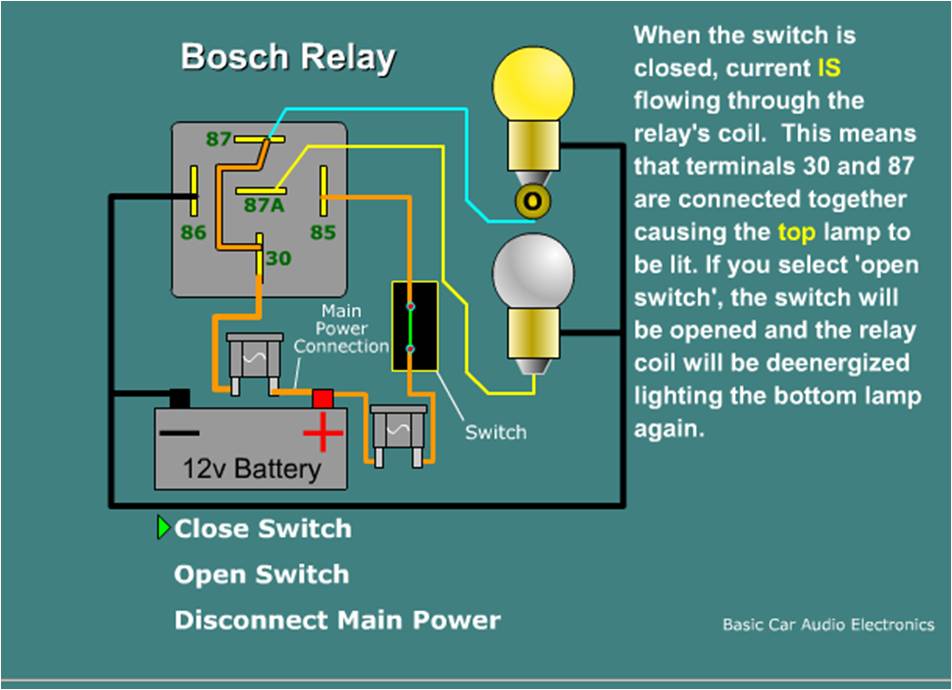
I'm running the LS1 compressor with my factory oem system. I have the usual dual high/ low fan setup that is controled via the pcm when engine reaches temp. My compressor is controlled outside of the pcm with the standard a/c 12v request. I added 2 relays to the 12v request so that both fans kick on when the a/c compressor does. Relay Wiring diagram below

Teching In
Joined: Nov 2012
Posts: 4
Likes: 0
rockytopper said more of what i was thinking. put as simply as i can explain it. cut lt blu 409, plug 30 to lt blue 409 going to the fan, 87a to lt blue 409 on the relay side. (current goes directly trhough the circut when relay isn't powered) then splice 87 to red 402 (hot all times), splice 85 to 18 dk green (+ when a/c activated), and 86 to ground. this would turn fans on low speed while a/c is running and allow them to operate normally when a/c is off
The only problem with having the fans wired to come on whenever the A/C is turned on is that the fans will be on even when they're not needed. When you're running down the highway at 70mph, you won't need a fan, but it'll still be on. With the trinary switch, the head pressure running down the highway won't be as high due to good air flow so the fans would be off. It won't really hurt anything running them all the time, but may shorten the life of the fan.
You're missing one other aspect. VA does not use a simple 12 V AC request channeled through a thermostat like on old cars. It's a computer controlled system. They specifically say NOT to to wire anything to the compressor relay circuit.
Just do it right and use the trinary switch.
Just do it right and use the trinary switch.
TECH Resident
Joined: Nov 2007
Posts: 816
Likes: 0
From: Texas
My bad I'm not familiar with the VA system I always read that they also state a LS1 compressor want work with their system either.
I totally agree the best way is to run the a/c through the PCM and have it be the brains. It controls engine idle and a host of other things like cutting the compressor off at WOT apparently saves the life of the compressor. It works on old systems wired as stated.
I totally agree the best way is to run the a/c through the PCM and have it be the brains. It controls engine idle and a host of other things like cutting the compressor off at WOT apparently saves the life of the compressor. It works on old systems wired as stated.

Teching In

Joined: Nov 2012
Posts: 17
Likes: 0
I know I'm resurrecting this one a little bit but........if I use the VA trinary I will basically cut the green wire to my compressor and wire it through two of the switch leads and then the third wore from the switch would go to a 3rd fan relay?
Edit to add: this is going on a 72 C10 with aftermarket a/c. Using factory LQ4 compressor. No pressure switch. Body fans controlled by PCM. I will be wiring up the a/c request signal through the PCM.
Edit to add: this is going on a 72 C10 with aftermarket a/c. Using factory LQ4 compressor. No pressure switch. Body fans controlled by PCM. I will be wiring up the a/c request signal through the PCM.


I realize this is an old thread but I've gone blind reading posts on this subject. Here's what I have...
Modified '05 5.3 truck harness. The PCM is operating a two-speed Cooling Components fan. I want the PCM to be in the loop because it sends the signal for the high speed on the fans to come on. Only one green wire for A/C coming into the cabin. Here's the harness builder's description of that wire...
Pigtail Wire Identifications.
AC Compressor
The green wire that is marked AC compressor (or similar identification) is connected to wire from the vehicle that normally feeds power to the compressor. This is a 12V power that is energized through your vehicle’s climate control system.
I have the factory harness connection on the A/C compressor (one green, one black)
There is another unused factory harness plug near the firewall that I labeled A/C drier (one blue, one black wire).
I've got the Vintage Air unit installed. Trying to wire the Trinary switch but have gotten confused. Any assistance is appreciated. This electrical stuff just whips my a**.
Last edited by 1936 LS1; Oct 5, 2014 at 05:56 PM. Reason: addition
In order for the PCM to control the A/C, you would need to wire it like an Express van, which means moving some wires in the harness and at the PCM, and have the tune set up for 12v A/C request rather than serial request like the trucks. But then im not totally sure about the fans since vans have mechanical fans, but I would think it would work.
In order for the PCM to control the A/C, you would need to wire it like an Express van, which means moving some wires in the harness and at the PCM, and have the tune set up for 12v A/C request rather than serial request like the trucks. But then im not totally sure about the fans since vans have mechanical fans, but I would think it would work.