
Custom Long Tube Header / Exhaust Build ***DYNO Results are In***
 07-22-2013, 10:24 AM
#101
11 Second Club
Thread Starter
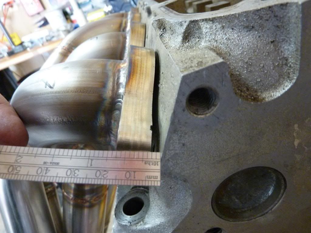
The end of the flange on the drivers side at #7 seems to be off between 1/16" - 1/8". Unfortunately I think it's going to take more than just a gasket to seal it up.
What about heating it up to get it mostly straight, then having them milled flat?
My concern with only milling them is that it would take too much meat off the flange and remove too much of the welds on the insides of the tubing.
From my experience, I would not do the cuts between cylinders. If they are warped now, they will be even worse after they heat cycle 100's of times.
Either heating or milling will work, but heating the flange to make the flange flat puts more stress in the tubes which can make them crack after long term use.
I'd mill them. It's the most reliable long term option, which if I were to guess, is probably why you built with stainless to begin with.
And nothing is warp proof.
My concern with only milling them is that it would take too much meat off the flange and remove too much of the welds on the insides of the tubing.
 07-22-2013, 10:40 AM
#102

From my experience, I would not do the cuts between cylinders. If they are warped now, they will be even worse after they heat cycle 100's of times.
Either heating or milling will work, but heating the flange to make the flange flat puts more stress in the tubes which can make them crack after long term use.
I'd mill them. It's the most reliable long term option, which if I were to guess, is probably why you built with stainless to begin with.
And nothing is warp proof.
Either heating or milling will work, but heating the flange to make the flange flat puts more stress in the tubes which can make them crack after long term use.
I'd mill them. It's the most reliable long term option, which if I were to guess, is probably why you built with stainless to begin with.
And nothing is warp proof.
I don't see an issue with cutting the flanges to make them individual. As long as they are bolted to the heads when they heat cycle, they should take the form of the head. Motorcycles and European cars all have separate flanges and don't have any issues.
07-22-2013, 12:19 PM
#103
TECH Resident

Join Date: Nov 2009
Posts: 751
Likes: 0
Received 0 Likes
on
0 Posts

Ideally welding them together while bolted to a head would have been the best option.. thus using the aluminum as a heat sink and preventing warpage.. as well as holding them flat..
Have them milled.. heating and pulling will cause cracks..
Have them milled.. heating and pulling will cause cracks..
07-22-2013, 01:33 PM
#104
11 Second Club
Thread Starter
I suggested that since I had old heads laying around anyway but they didn't think they would be able to get enough heat in the flange doing it that way.
07-22-2013, 03:01 PM
#105
TECH Enthusiast

Join Date: Feb 2007
Location: Raleigh, NC
Posts: 625
Likes: 0
Received 0 Likes
on
0 Posts
The end of the flange on the drivers side at #7 seems to be off between 1/16" - 1/8". Unfortunately I think it's going to take more than just a gasket to seal it up.
What about heating it up to get it mostly straight, then having them milled flat?
My concern with only milling them is that it would take too much meat off the flange and remove too much of the welds on the insides of the tubing.
What about heating it up to get it mostly straight, then having them milled flat?
My concern with only milling them is that it would take too much meat off the flange and remove too much of the welds on the insides of the tubing.
I did not realize the extent to which they had warped. If it's .063" or larger, that's a whole lot more than I expected. I suspect you will have to heat then mill. If there was .020" of warpage then milling only, no issue at all. If you have to cut .100" off the flange, that's alot more than I would want to do.
Mount to the head, tighten the bolts you can tighten without putting alot of stress into to flange/tubes, heat required areas with a torch and tighten the rest while hot / heating, then let it all cool. After that, mill flat.
I've been tacking my headers (modified steel Mustang Accufabs, 3/8" steel ebay flanges) with the flange bolted to the head and the tubes in the ports. Granted, I'm tacking with a TIG so I can heat on the flange for a bit before I move the puddle towards the tube and dip in the filler rod. It would be a little harder with the MIG because of the material thickness differences, and the giant aluminum heat sink
If you cut them, you will have to cut between the two bolts in the center of the flange, otherwise cutting elsewhere the port near the cut will not have an exhaust bolt on each side of the seal, and that port with the missing bolt will leak. Unless you can cut through the center of the bolt hole, and then use a thick washer to clamp both sides.
07-24-2013, 10:15 PM
#106
11 Second Club
Thread Starter
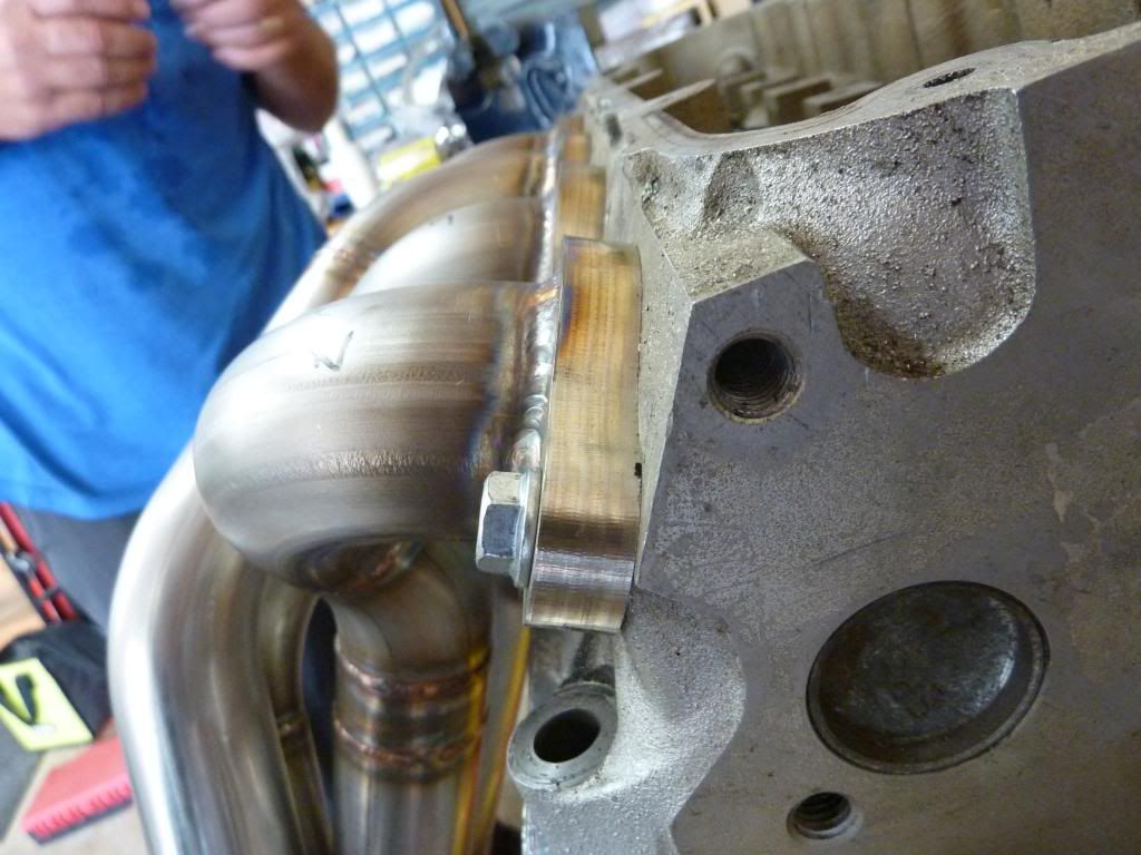
Made some progress today. Dad came by and we decided to file off the excess welds on the head side of the flange to see exactly how far things were out of whack. Upon close inspection, the warping on the drivers side is at cylinder #5 and the gap just gets larger toward #7. Here's a shot of it without #5 and #7 bolted down.
Since we were just test fitting them on some old heads we decided to see how hard it would be to tighten down the last 2 bolts. Much to my surprise it tightened down with very little force....definitely less than the recommended 20ft/lbs. Crisis #1 averted!
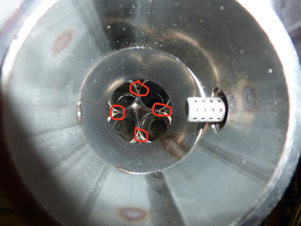
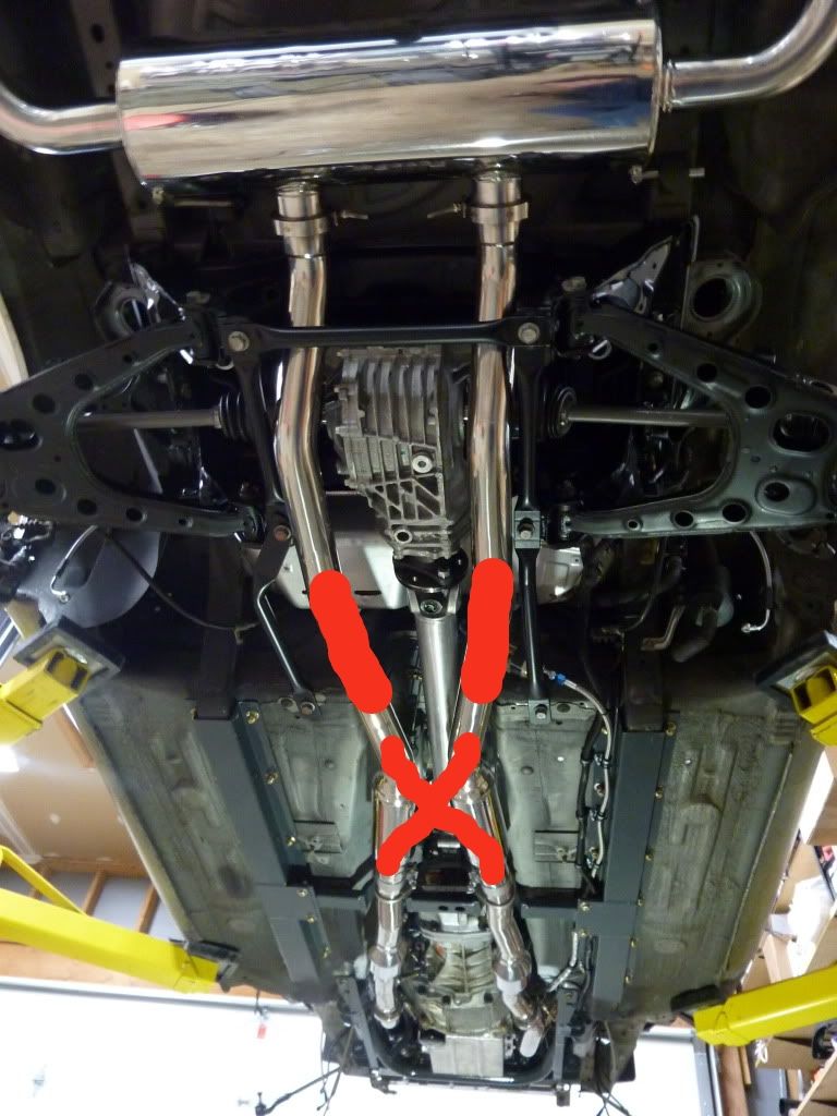
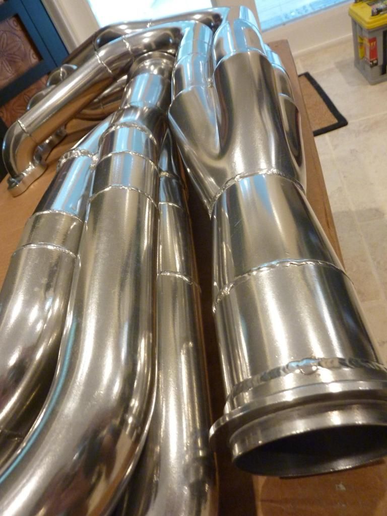
Next I decided test for leaks. I covered the flange end with tape and blew into the collector to see if I could hear air escaping anywhere. Turns out there are a couple leaks where the collector slides onto the primaries. Not exactly sure how to fill the gaps now that it's all welded together Here's the spots that are leaky.
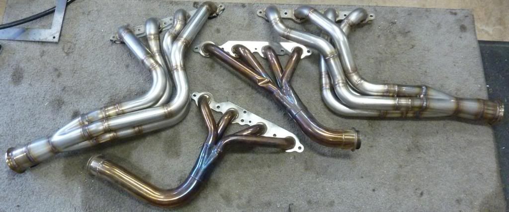
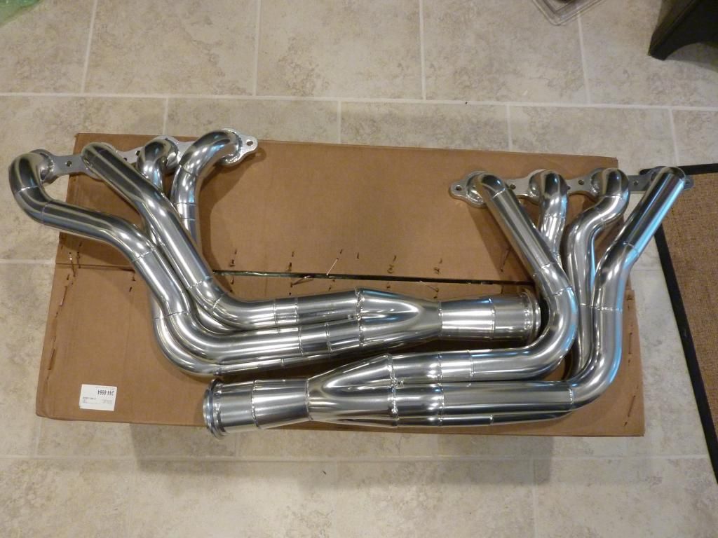
And lastly, a shot next to the shortys.

Since we were just test fitting them on some old heads we decided to see how hard it would be to tighten down the last 2 bolts. Much to my surprise it tightened down with very little force....definitely less than the recommended 20ft/lbs. Crisis #1 averted!

Next I decided test for leaks. I covered the flange end with tape and blew into the collector to see if I could hear air escaping anywhere. Turns out there are a couple leaks where the collector slides onto the primaries. Not exactly sure how to fill the gaps now that it's all welded together
Here's the spots that are leaky. 
And lastly, a shot next to the shortys.
 07-24-2013, 11:51 PM
#107
Great job on the headers, I'm going to have to try my hand at a set.
I've seen people weld the bits where you have leaks straight off when they weld the cone, then carry on to the rest. I don't know of another way to get that area without separating the merge and collector.
I've seen people weld the bits where you have leaks straight off when they weld the cone, then carry on to the rest. I don't know of another way to get that area without separating the merge and collector.
 07-29-2013, 10:04 PM
#110
11 Second Club
Thread Starter

Filed the extra welds on the flange down flat and smoothed out the insides of the primaries.

Headers all packed up and ready for ceramic coating.
 07-31-2013, 10:12 AM
#112
11 Second Club
Thread Starter
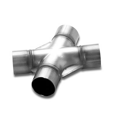
Right now my plan is to use this Magnaflow X-pipe after the trans mount then a couple of these Vibrant resonators between the X-pipe and axle. The resonators will quiet the car down some and resemble catalytic converters. I haven't decided what I'm going to do for mufflers yet. I'd also like to run cut-outs, so a quiet muffler would be better.


Last edited by MX6.0; 08-01-2013 at 09:12 PM.
08-03-2013, 06:06 PM
#113
Nice man, your dad did a great job.
Stainless stick welding is awesome, so clean.
Have you thought about Magna packs for another resonator?
Who's doing the ceramic coating?
Stainless stick welding is awesome, so clean.
Have you thought about Magna packs for another resonator?
Who's doing the ceramic coating?
08-03-2013, 09:38 PM
#114
11 Second Club
Thread Starter
Just got my emissions notice, so I have until October 2nd to figure it out. lol
08-04-2013, 07:41 PM
#118
You mean the straight through round ones? I actually bought a couple 14419's but they are too long to fit between the X pipe and the rear. I was considering using them sideways behind the axle but I'm not sure they'll be quiet enough.
Just got my emissions notice, so I have until October 2nd to figure it out. lol
Just got my emissions notice, so I have until October 2nd to figure it out. lol
Hmm you're right, they might not quiet it down enough.
I know Burns makes some decent re-buildable mufflers. Maybe you could look into them and maybe throw some extra packing in them. They have quite the selection to.
Maybe you could throw a couple of high flow cats in instead of mufflers.
You have a little time
08-12-2013, 06:29 PM
#119
11 Second Club
Thread Starter
Had a big box waiting for me when I got home today. Lucy couldn't wait to see what was inside.
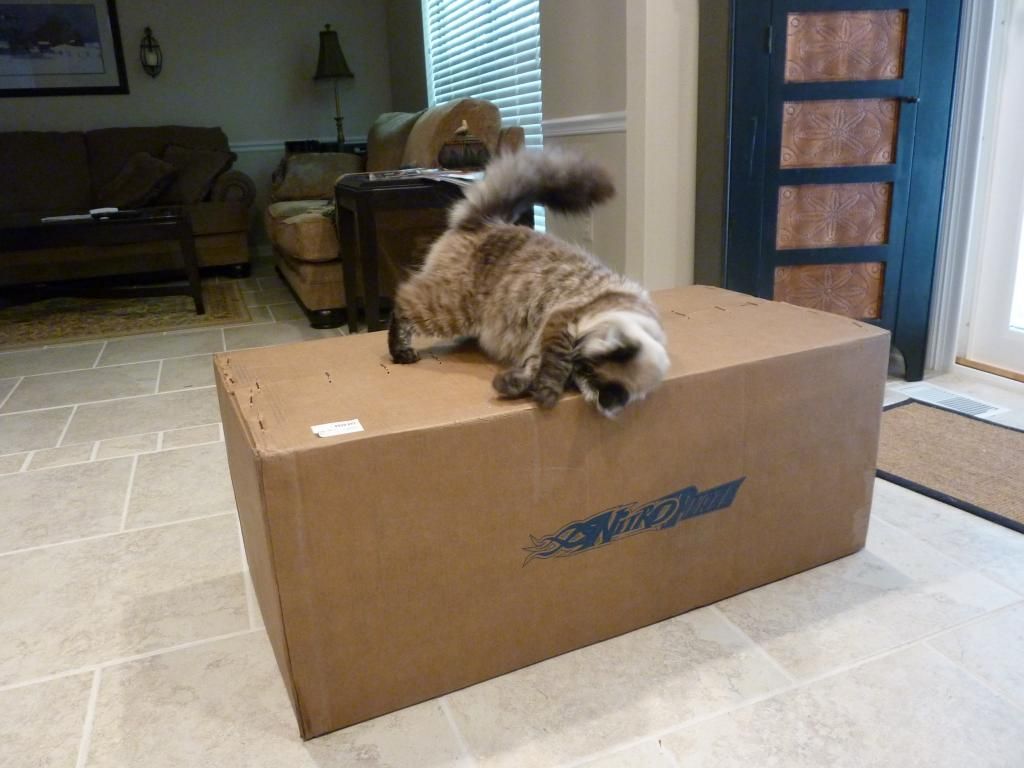
NitroPlate couldn't have done a better job on the ceramic coating....and they got them back to me ahead of schedule!
Turns out the Magnaflow X-Pipe I ordered from Summit isn't going to work. It's just too wide to fit up high enough in the transmission tunnel. So after looking around for a while I figured I'd see about making my own.
After some measurements I decided how I wanted them positioned. Next step was to figure out where to cut the 45* bends. For this I plan on using a 2" wide ruler and marking straight lines (or as straight as I can get) with a sharpie.
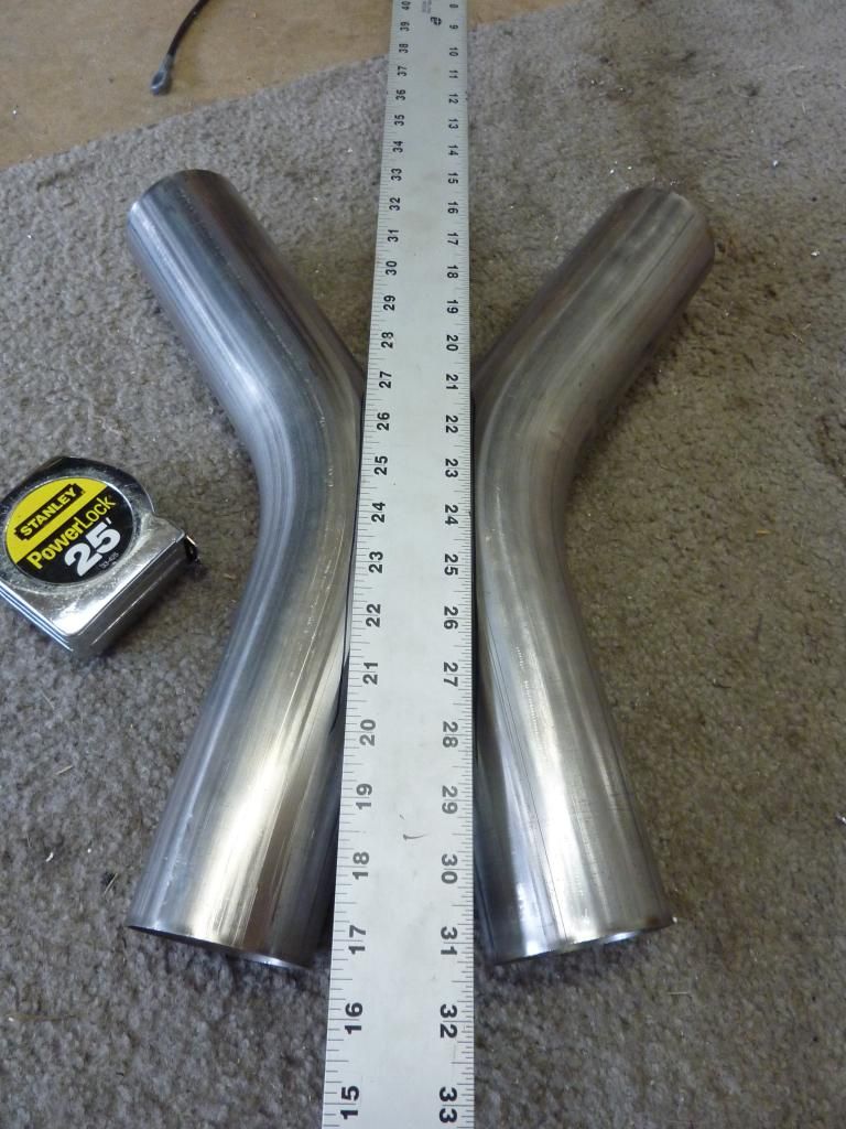
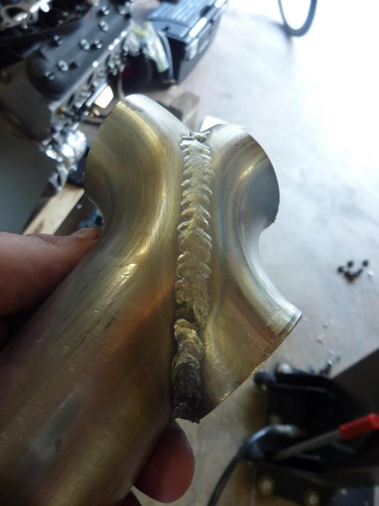
Before possibly ruining 2 expensive stainless pipes I decided to try to make one out of the 1 7/8" header scrap pipe. I did one quickly just to see how it would turn out and was surprised how easy it was to get both sides relatively equal. Here's how the mini X-pipe turned out. Tomorrow I'll make the full scale version.

NitroPlate couldn't have done a better job on the ceramic coating....and they got them back to me ahead of schedule!


Turns out the Magnaflow X-Pipe I ordered from Summit isn't going to work. It's just too wide to fit up high enough in the transmission tunnel. So after looking around for a while I figured I'd see about making my own.
After some measurements I decided how I wanted them positioned. Next step was to figure out where to cut the 45* bends. For this I plan on using a 2" wide ruler and marking straight lines (or as straight as I can get) with a sharpie.

Before possibly ruining 2 expensive stainless pipes I decided to try to make one out of the 1 7/8" header scrap pipe. I did one quickly just to see how it would turn out and was surprised how easy it was to get both sides relatively equal. Here's how the mini X-pipe turned out. Tomorrow I'll make the full scale version.
 08-12-2013, 07:16 PM
#120

As you noticed, slow your speed down some. I am sure it was because it was practice pc. Headers look great!!!