
1967 Cougar build (over 500 pictures and videos)
 05-18-2015, 09:17 PM
#421
TECH Senior Member
Thread Starter
iTrader: (7)

Finished up the pedal mount project tonight. First, I wanted to get rid of the ugly looking foot pad on the pedal assembly. The foot pad is held in place by a pin, so I ground the head and it popped right out.
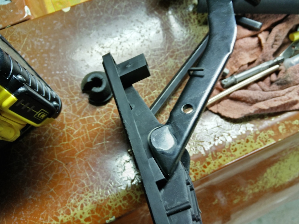
Next, I tapped the existing hole in the pedal arm so that the original screw that held the Cougar pedal in place would screw right in, and presto!
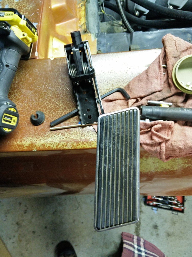
Once that was done, I figures out where the pedal needs to go, drilled a couple of holes and used some 6mm studs that used to hold the stock coils and welded them to the backside of the bracket I made prior.
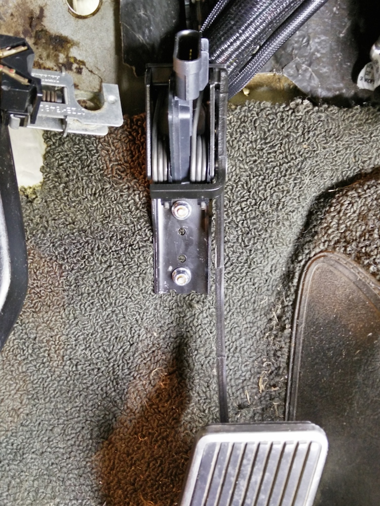
Nice pedal placement and from a casual look, it looks like the stock pedal.
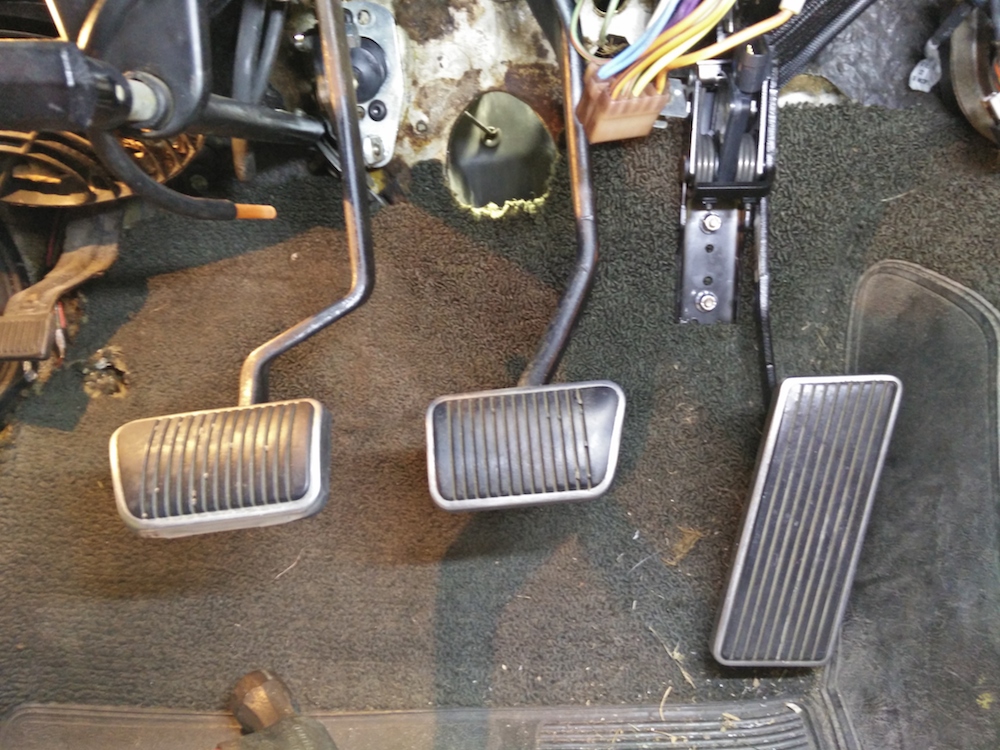
With the pedal where it is, there is even easy access to the fuse panel.

Andrew
Next, I tapped the existing hole in the pedal arm so that the original screw that held the Cougar pedal in place would screw right in, and presto!
Once that was done, I figures out where the pedal needs to go, drilled a couple of holes and used some 6mm studs that used to hold the stock coils and welded them to the backside of the bracket I made prior.
Nice pedal placement and from a casual look, it looks like the stock pedal.
With the pedal where it is, there is even easy access to the fuse panel.
Andrew
 05-21-2015, 07:29 PM
#422
TECH Senior Member
Thread Starter
iTrader: (7)
Not much progress, but I did get my MT front radials and had them mounted.

Tomorrow I plan to tackle the rest of the under dash wiring and hopefully have that all ironed out.
Andrew
Tomorrow I plan to tackle the rest of the under dash wiring and hopefully have that all ironed out.
Andrew
05-23-2015, 10:23 PM
#423
TECH Senior Member
Thread Starter
iTrader: (7)
Today I tackled more of the wiring. With all of the wiring modifications that I have made, there is probably less wiring that I haven't touched, then what I have. I have installed relays for the headlights and for the electronic headlight covers. The wiring that I have added for the engine is pretty much standalone, but a few wires need to be integrated with the car harness to make it all work well.
The bulk of today's work centered around making the input/output harness that comes with the Dominator ECU. I got the auxiliary harness from Holley, PM 558-400. This harness mates with the main harness through an existing connector. There are 4/4 inputs/outputs that can be programmed and assigned various functions. As noted earlier in a video, I assigned one of the outputs to be a PWM- for fan speed control. Here is how I assigned the pins:

What is not listed is pin B12. I used that as the power output for the reverse lockout solenoid. So a portion of the I/O harness has essentially been made into the T56 transmission harness. Pin B3 acts as the ground for both the VSS and the reverse lockout solenoid. This pin was programmed to come on when coolant temps are below -30 degrees, in other words, always on. Pin B12 was programmed to energize when vehicle speed is below 5 MPH. This is exactly how the factory ECU handles the reverse lockout solenoid so that you can't accidentally shift into reverse when driving.
Pin A4 serves as the VSS input which will feed a speed signal to the ECU and also display the speed on the Holley digital dash.
As noted earlier, pin B10 is the PWM- output for the fan controller. Pin B11 is there to turn on the alternator. This pin was programmed to energize whenever RPM was above 250. So when the engine is cranking during start, the alternator will not produce any current, but as soon as the engine starts, it will activate the alternator and start charging and powering the main electrical systems.
Also not labeled is pin A3. This pin will be activated when the line lock is activated, which will tell the ECU to enable the secondary rev limiter. So I will be able to stage at whatever RPM I want.
Andrew
The bulk of today's work centered around making the input/output harness that comes with the Dominator ECU. I got the auxiliary harness from Holley, PM 558-400. This harness mates with the main harness through an existing connector. There are 4/4 inputs/outputs that can be programmed and assigned various functions. As noted earlier in a video, I assigned one of the outputs to be a PWM- for fan speed control. Here is how I assigned the pins:
What is not listed is pin B12. I used that as the power output for the reverse lockout solenoid. So a portion of the I/O harness has essentially been made into the T56 transmission harness. Pin B3 acts as the ground for both the VSS and the reverse lockout solenoid. This pin was programmed to come on when coolant temps are below -30 degrees, in other words, always on. Pin B12 was programmed to energize when vehicle speed is below 5 MPH. This is exactly how the factory ECU handles the reverse lockout solenoid so that you can't accidentally shift into reverse when driving.
Pin A4 serves as the VSS input which will feed a speed signal to the ECU and also display the speed on the Holley digital dash.
As noted earlier, pin B10 is the PWM- output for the fan controller. Pin B11 is there to turn on the alternator. This pin was programmed to energize whenever RPM was above 250. So when the engine is cranking during start, the alternator will not produce any current, but as soon as the engine starts, it will activate the alternator and start charging and powering the main electrical systems.
Also not labeled is pin A3. This pin will be activated when the line lock is activated, which will tell the ECU to enable the secondary rev limiter. So I will be able to stage at whatever RPM I want.
Andrew
05-23-2015, 10:38 PM
#424
Have you balanced those MT's yet? My boss put a set on the front of his Mustang and they took a lot of weight, about 5oz which is ridiculous for a 15x4 rim and a tire that small. We checked the balance on the wheel and it was damn near perfect(Weld RTS). Both front tires were like that. I'm just curious to what your experiences are with them.
05-23-2015, 10:45 PM
#425
TECH Senior Member
Thread Starter
iTrader: (7)
Have you balanced those MT's yet? My boss put a set on the front of his Mustang and they took a lot of weight, about 5oz which is ridiculous for a 15x4 rim and a tire that small. We checked the balance on the wheel and it was damn near perfect(Weld RTS). Both front tires were like that. I'm just curious to what your experiences are with them.
I got these instead:
http://www.innovativebalancing.com
Time will tell if it works!
Andrew
05-23-2015, 11:13 PM
#426
Now you are scaring me. Five ounces is A LOT for small tires. I didn't have them balanced because there is no room even on the inside lip for weights because of the calipers.
I got these instead:
http://www.innovativebalancing.com
Time will tell if it works!
Andrew
I got these instead:
http://www.innovativebalancing.com
Time will tell if it works!
Andrew
As far as the beads for balancing we use them on the big trucks we work on and they work great( I don't remember what brand we use). They ride rough at first but after a few miles they smooth out.
05-23-2015, 11:17 PM
#427
TECH Senior Member
Thread Starter
iTrader: (7)
Sorry man, lol. That wasn't my intent. We tried everything. Spun them 180 degrees on the rim, then 90, it didn't make a difference. That's when we checked the wheel. We put a set of Hoosiers on and they wanted less that 1 oz.
As far as the beads for balancing we use them on the big trucks we work on and they work great( I don't remember what brand we use). They ride rough at first but after a few miles they smooth out.
As far as the beads for balancing we use them on the big trucks we work on and they work great( I don't remember what brand we use). They ride rough at first but after a few miles they smooth out.
Andrew
05-24-2015, 09:39 PM
#428
TECH Addict
iTrader: (19)
Join Date: Aug 2007
Location: Where the Navy tells me to go
Posts: 2,405
Received 106 Likes
on
88 Posts

Or maybe the description is correct, and you live on Hoth?
 05-24-2015, 09:47 PM
#429
05-27-2015, 10:17 PM
#430
TECH Senior Member
Thread Starter
iTrader: (7)
Today I accomplished another little wiring project. There is a stock connector that mates the steering column to the main power harness. The connector was very brittle and wouldn't properly go together. I am not sure what the problem was, but when the connectors were mated, I could definitely feel it getting hot to the touch, which to me indicates a lot of resistance in the connector. Here is the old connector compared to the new one:

The new connector is a Delphi GT280 series connector. It is rated up to 25 amps, and should be more than adequate for whatever runs through the steering column harness. Here are the new male terminals for the connector:

I cut the old wires from the steering column connector and made new terminals to go into the GT280 connector.

Under the dash I cut off the wires for the mating connector and terminated the wires into the female connector.

This should make for a much nicer mating connector and eliminate any resistance that might have been present in the 50 year old stock Ford connector.
I also picked up a couple of 75amp relays with the proper female mating ends (Delphi series 56 connectors). This relay will be used to provide auxiliary power under the dash and will be activated through the stock wire that used to run to the coil. This will ensure power when the ignition switch is in both the RUN and the START positions.

I also got some Delphi Series 480 3 cavity connectors.

The GT480 connectors are rated at 42 amps and I will use it to connect the fan for power and PWM signal. With the PWM fan activation there are no current spikes when the fan is turned on, so I see no issue with using this connector.
Andrew
The new connector is a Delphi GT280 series connector. It is rated up to 25 amps, and should be more than adequate for whatever runs through the steering column harness. Here are the new male terminals for the connector:
I cut the old wires from the steering column connector and made new terminals to go into the GT280 connector.
Under the dash I cut off the wires for the mating connector and terminated the wires into the female connector.
This should make for a much nicer mating connector and eliminate any resistance that might have been present in the 50 year old stock Ford connector.
I also picked up a couple of 75amp relays with the proper female mating ends (Delphi series 56 connectors). This relay will be used to provide auxiliary power under the dash and will be activated through the stock wire that used to run to the coil. This will ensure power when the ignition switch is in both the RUN and the START positions.
I also got some Delphi Series 480 3 cavity connectors.
The GT480 connectors are rated at 42 amps and I will use it to connect the fan for power and PWM signal. With the PWM fan activation there are no current spikes when the fan is turned on, so I see no issue with using this connector.
Andrew
05-28-2015, 11:59 AM
#432
TECH Resident

I use one of those same 75 amp relays for my ignition "on". I like that you can attach large gauge feed and load wires with the machine screw connectors. Much better than the Bosch cube relays for higher current application or routing that current through the ignition switch itself.
Those Delphi connectors look great! Did you post what crimper you use for the terminals?
thanks,
Doug
Those Delphi connectors look great! Did you post what crimper you use for the terminals?
thanks,
Doug
05-28-2015, 03:11 PM
#433
TECH Senior Member
Thread Starter
iTrader: (7)
I use one of those same 75 amp relays for my ignition "on". I like that you can attach large gauge feed and load wires with the machine screw connectors. Much better than the Bosch cube relays for higher current application or routing that current through the ignition switch itself.
Those Delphi connectors look great! Did you post what crimper you use for the terminals?
thanks,
Doug
Those Delphi connectors look great! Did you post what crimper you use for the terminals?
thanks,
Doug
Andrew
05-30-2015, 10:48 AM
#434
TECH Senior Member
Thread Starter
iTrader: (7)
Not a terribly exciting update, but I got most of the Dominator wiring tucked in and wired up. Ran a 10 gauge wire from the battery to bring in power to turn on the ECU. That relay is triggered off the ignition switch from a wire that used to feed power to the coil, so it stays ON in RUN and START. That relay provides power for the injectors and coils (big red wire on the Holley harness), the ECU power up wire (red/white), and also power for the digital dash display.
I also ran a ground strap from the engine to the firewall, and added another ground strap from the engine to a stud that runs through the firewall. Can't have too many grounds!

The Dominator ECU is huge, but fits nicely on the back of the glove box door. I hate loosing the glove box, but this will keep me from throwing junk in it, plus it gives me super easy access to all the under dash wiring just by opening the glove box door.

To top off a productive day, I was able to start the engine using the key for the first time.
Andrew
I also ran a ground strap from the engine to the firewall, and added another ground strap from the engine to a stud that runs through the firewall. Can't have too many grounds!
The Dominator ECU is huge, but fits nicely on the back of the glove box door. I hate loosing the glove box, but this will keep me from throwing junk in it, plus it gives me super easy access to all the under dash wiring just by opening the glove box door.
To top off a productive day, I was able to start the engine using the key for the first time.
Andrew
05-31-2015, 10:07 AM
#435

any plans on a short running video? You know that was coming.
 06-01-2015, 09:51 AM
#437
TECH Senior Member
Thread Starter
iTrader: (7)
Still plugging away on the wiring. Yesterday I made a short little power harness that goes directly from the battery to a couple of 40 amp circuit breakers. One is for the headlights and the headlight door relays, the other is for powering the cooling fan.


Andrew
Andrew
06-01-2015, 12:57 PM
#438
TECH Senior Member
Thread Starter
iTrader: (7)
I also did a little wiring on the fan. Dorman's Ching Chong suppliers of these fans seems to not understand that the wires have to be long enough for the controller to fit into the slot in the shroud, and so the power wires that go from the controller to the fan are too short. I lengthened those wires using some 10 gauge wire with crimp and solder connectors, covered with glue lined heat shrink tubing. This is the fan controller mounted to the shroud and the Delhi connector.

I had previously thought that I wasn't going to be able to mount the controller on the shroud because of the angled lower radiator outlet, but since I had previously modified it and there is a smaller 1.5" hose being used at the bottom, the shroud fits in place and the controller fits nicely on the shroud.

Now I need to make a short harness that connects to the Delphi plug on the controller to give it power, ground, and the PWM wire from the Dominator.
Andrew
I had previously thought that I wasn't going to be able to mount the controller on the shroud because of the angled lower radiator outlet, but since I had previously modified it and there is a smaller 1.5" hose being used at the bottom, the shroud fits in place and the controller fits nicely on the shroud.
Now I need to make a short harness that connects to the Delphi plug on the controller to give it power, ground, and the PWM wire from the Dominator.
Andrew
06-01-2015, 06:17 PM
#439
Great work as always Andrew. I really like your harness wrap. Looks high end IMO. (DSE). Didn't you use a shrink tubing? Any particular kind and brand that works best?
thanks,
Jim
thanks,
Jim
06-01-2015, 06:30 PM
#440
TECH Senior Member
Thread Starter
iTrader: (7)
I get it here:
http://www.prowireusa.com/c-31-dsg-v25-.aspx
Andrew