
1967 Cougar build (over 500 pictures and videos)
 06-11-2015, 11:07 PM
#481
TECH Senior Member
Thread Starter
iTrader: (7)

The next order of business was to get the strut rod installed. The strut rod bushing is a thing of beauty. Gone is the squishy rubber joint which is replaced by this beautiful solid ball joint.

It is greasable and has a broad range of smooth travel which will result in no binding in the suspension.

It fits firmly in the stock location and is captured by this giant nut which has a pocket for a 1/2" ratchet machined into the end of it. This allows a torque wrench to be attached directly, so it can be torqued to 150 lb/ft. There is a screw that covers the 1/2" ratted hole.

Once the other end of the strut rod was attached loosely to the lower control arm, the next order of business as to work on the upper coil over mount. The first thing to do was to use a spot weld drill to remove the stock spring perch. The drill was included in the TCP kit. First spot weld drilled.

All three spot welds and the spring perch removed. The spot welds were smoothed out and a coat of undercoating sprayed on.

Next was the upper coil over mount. Here is the top plate.

There is also a reinforcing plate that goes underneath. So the top and bottom plates sandwich the top of the shock tower, which makes for a very strong location for the coilovers.

The top of the coil over is attached through the big middle hole. There is a greasable wobble joint at the top. The zerk fitting is removable and will be replaced by a little chrome cover.

I then mocked up the coil over without the spring so that I could check for any bind. Everything cycled freely through the full range of motion of the shock.

To be continued...
Andrew
It is greasable and has a broad range of smooth travel which will result in no binding in the suspension.
It fits firmly in the stock location and is captured by this giant nut which has a pocket for a 1/2" ratchet machined into the end of it. This allows a torque wrench to be attached directly, so it can be torqued to 150 lb/ft. There is a screw that covers the 1/2" ratted hole.
Once the other end of the strut rod was attached loosely to the lower control arm, the next order of business as to work on the upper coil over mount. The first thing to do was to use a spot weld drill to remove the stock spring perch. The drill was included in the TCP kit. First spot weld drilled.
All three spot welds and the spring perch removed. The spot welds were smoothed out and a coat of undercoating sprayed on.
Next was the upper coil over mount. Here is the top plate.
There is also a reinforcing plate that goes underneath. So the top and bottom plates sandwich the top of the shock tower, which makes for a very strong location for the coilovers.
The top of the coil over is attached through the big middle hole. There is a greasable wobble joint at the top. The zerk fitting is removable and will be replaced by a little chrome cover.
I then mocked up the coil over without the spring so that I could check for any bind. Everything cycled freely through the full range of motion of the shock.
To be continued...
Andrew
 06-11-2015, 11:20 PM
#482
TECH Senior Member
Thread Starter
iTrader: (7)
Here is what I need up doing with the spindle booboo. I talked it over with my buddy John, and he encouraged me to smooth out the slice to reduce the chances of a stress riser coming through the slice. I removed a bit more material around the slice to form a V and smoothed it out with a flapper wheel.

I also cleaned up the spindle and gave it a Rustoleum restoration.

Spindle mounted.

To be continued...
Andrew
I also cleaned up the spindle and gave it a Rustoleum restoration.
Spindle mounted.
To be continued...
Andrew
06-11-2015, 11:46 PM
#483
TECH Senior Member
Thread Starter
iTrader: (7)
Once the suspension was cycled through its range of motion, it was time to install the spring on the shock.

I am using a 400 lb/in spring that is 9" long. Once the spring was installed, I had to see how she would sit, so I took her off the jack stands for a look...

With the 400 pound springs the shock is a little more compressed than is ideal, but it is close. I spoke with Carl at TCP and he suggested that I can preload the spring just a little to raise it up a hair and place the shock in the idea spot at ride height. The current measurements are probably also a little off, since the driver's side sits about 1.5" higher. I am thinking that this is causing the passenger side to be loaded more than it would be when both sides have the same set-up installed. So for now I am leaving it alone and will get working on the other side. I can always get some 450 pound springs later.
Andrew
I am using a 400 lb/in spring that is 9" long. Once the spring was installed, I had to see how she would sit, so I took her off the jack stands for a look...
With the 400 pound springs the shock is a little more compressed than is ideal, but it is close. I spoke with Carl at TCP and he suggested that I can preload the spring just a little to raise it up a hair and place the shock in the idea spot at ride height. The current measurements are probably also a little off, since the driver's side sits about 1.5" higher. I am thinking that this is causing the passenger side to be loaded more than it would be when both sides have the same set-up installed. So for now I am leaving it alone and will get working on the other side. I can always get some 450 pound springs later.
Andrew
06-13-2015, 11:42 AM
#484
TECH Senior Member
Thread Starter
iTrader: (7)
Made good progress yesterday on the driver's side suspension. Got all the old stuff off, cleaned up the inside of the shock towers, removed the spring pocket at the top of the shock tower, cleaned up and painted the spindle, and installed the upper, lower control arms and the strut rod. Sorry for the blurry picture, but you get the idea...LOL

The old brake line on this side was rusted to the tube nut, so when I tried to take the hardline off the flex line fitting, it just twisted the line off. Luckily I still have plenty of 3/16 NiCopp tubing, so I bent up a new line using the old one as a template. I also installed the Earl's 3/8" x 24 inverted flare to AN-3 adapter.

Hoping to wrap up that side today.
Andrew
The old brake line on this side was rusted to the tube nut, so when I tried to take the hardline off the flex line fitting, it just twisted the line off. Luckily I still have plenty of 3/16 NiCopp tubing, so I bent up a new line using the old one as a template. I also installed the Earl's 3/8" x 24 inverted flare to AN-3 adapter.
Hoping to wrap up that side today.
Andrew
 06-14-2015, 11:54 AM
#487
TECH Senior Member
Thread Starter
iTrader: (7)
Yesterday I wrapped up the driver's side suspension installation. There are still a bunch of things to do before it's all installed for good, but I needed the car on the ground so that I could measure the coil overs to determine if I need heavier springs. Measuring from the ground to the top of the wheel well opening at the centers of the wheels the rear sits about 1" higher than the front, so it has a little rake. The driver's side front is about 1/4" higher then the passenger side, but it levels out when I sit in the car.
I had to preload the spring about 3/4" inch to get the ride height where I wanted. The VariShock instructions say that if the spring needs to be preloaded more than 1/2" then I need heavier springs. Here are the measurements for the driver's side:

At ride height the spring length is 5 5/8".
From the top of the spring to the top of the crossbar it is 8.5".The VariShock instruction state that this can't be less than 8.71". At my ride height length there is 1.5" of shock travel available for compression (8.5 - 7.0 = 1.5). Given a motion ratio of .54 that gives me 2.78" of wheel travel in compression.

I'll give TCP a call on Monday and see if this is OK. The last thing I want to do is damage the shocks. For drag racing they do say that using a softer spring and adding some preload is desirable, since there is more stored energy in the spring which will help weight transfer at launch.
Andrew
I had to preload the spring about 3/4" inch to get the ride height where I wanted. The VariShock instructions say that if the spring needs to be preloaded more than 1/2" then I need heavier springs. Here are the measurements for the driver's side:
At ride height the spring length is 5 5/8".
From the top of the spring to the top of the crossbar it is 8.5".The VariShock instruction state that this can't be less than 8.71". At my ride height length there is 1.5" of shock travel available for compression (8.5 - 7.0 = 1.5). Given a motion ratio of .54 that gives me 2.78" of wheel travel in compression.
I'll give TCP a call on Monday and see if this is OK. The last thing I want to do is damage the shocks. For drag racing they do say that using a softer spring and adding some preload is desirable, since there is more stored energy in the spring which will help weight transfer at launch.
Andrew
Last edited by Project GatTagO; 06-14-2015 at 12:03 PM.
06-14-2015, 01:04 PM
#488
I'll give TCP a call on Monday and see if this is OK. The last thing I want to do is damage the shocks. For drag racing they do say that using a softer spring and adding some preload is desirable, since there is more stored energy in the spring which will help weight transfer at launch.
Andrew
Andrew
I don't think you'll have any problem where you are now, I personally would not want anymore spring pressure then you have now..... The statement about drag racing is very true.....
Nice front end components, I was going that way if I kept the stock type front suspension..... Keep an eye on the cross pin in the bottom of those front shocks, I have seen them bend after a while on cars in the past.....
06-14-2015, 04:27 PM
#489
TECH Senior Member
Thread Starter
iTrader: (7)
Looking good.....
I don't think you'll have any problem where you are now, I personally would not want anymore spring pressure then you have now..... The statement about drag racing is very true.....
Nice front end components, I was going that way if I kept the stock type front suspension..... Keep an eye on the cross pin in the bottom of those front shocks, I have seen them bend after a while on cars in the past.....
Thanks for your input. I value your opinion!
Where the car sits now I can bounce the front end pretty hard and it doesn't seem to come close to bottoming out the spring or the shock. I will check in with TCP just to be sure, but I am inclined to think that it will be OK.
Andrew
06-14-2015, 05:57 PM
#490
TECH Senior Member
Thread Starter
iTrader: (7)
Some of the things that I post might be repetitive, but I enjoy documenting the whole build process as I progress. It was time to start the front suspension assembly for good. The hub got cleaned up and sprayed with Rustoleum spray over rust primer followed by a coat of semi-gloss high heat paint. This is what I refer to as a Rustoleum restoration...LOL

When I took the hubs apart and cleaned out the bearings, they looked mint. I saw no reason to go through the trouble of removing perfectly good made in the USA bearings. So I just repacked them (I am old school...I put a glob of grease in my hand and work it in to the bearing) and installed a new seal (not shown). Remember, inner bearing goes in first, then the seal...LOL

Then I packed the outer bearing, added some grease to the inside of the hub between the bearings and installed the washer and retaining nut. I seat the bearings gently with a crescent wrench, then back off the nut, tighten finger tight and install the nut retainer and cotter pin. I even reused the old cotter pin (note the proper orientation).

I then installed the rotor and the spacer and snugged then up with a few lug nuts to make it easier to install the caliper.

This side also needed a bit of the brake line replaced since when I was taking off the hardline fitting off the flex hose, the tube nut was rusted to the brake line and it twisted off. I picked a straight section in the line where I could install a brass union, then carefully flared the line. Remember the tube nut before you flare!

Once again I used the original brake line as a template and used my nifty brake line bending pliers to make the tight bends. I also installed the Earl's adapter to go to a AN-3 hose. Turned out pretty nice.

I then installed the caliper and the Earl's 17" brake hose. These come preassembled with a banjo fitting on one end and a AN-3 female on the other end. The hose is the right length and there is no binding or tight bending when the wheel is turned.

Final assembly of the brakes. I ended up painting the edge of the spacer black so it wouldn't be visible through the spokes (not pictured).

I like how the wheel and tire sit further out with the spacer installed. I was worried about the sidewall getting into the inner lip of the wheel well, but I think the suspension will bottom out before it catches the tire. I might have to be careful when making turns into a driveway, but for now it looks pretty good.

Now to do the other side...LOL
Andrew
When I took the hubs apart and cleaned out the bearings, they looked mint. I saw no reason to go through the trouble of removing perfectly good made in the USA bearings. So I just repacked them (I am old school...I put a glob of grease in my hand and work it in to the bearing) and installed a new seal (not shown). Remember, inner bearing goes in first, then the seal...LOL
Then I packed the outer bearing, added some grease to the inside of the hub between the bearings and installed the washer and retaining nut. I seat the bearings gently with a crescent wrench, then back off the nut, tighten finger tight and install the nut retainer and cotter pin. I even reused the old cotter pin (note the proper orientation).
I then installed the rotor and the spacer and snugged then up with a few lug nuts to make it easier to install the caliper.
This side also needed a bit of the brake line replaced since when I was taking off the hardline fitting off the flex hose, the tube nut was rusted to the brake line and it twisted off. I picked a straight section in the line where I could install a brass union, then carefully flared the line. Remember the tube nut before you flare!
Once again I used the original brake line as a template and used my nifty brake line bending pliers to make the tight bends. I also installed the Earl's adapter to go to a AN-3 hose. Turned out pretty nice.
I then installed the caliper and the Earl's 17" brake hose. These come preassembled with a banjo fitting on one end and a AN-3 female on the other end. The hose is the right length and there is no binding or tight bending when the wheel is turned.
Final assembly of the brakes. I ended up painting the edge of the spacer black so it wouldn't be visible through the spokes (not pictured).
I like how the wheel and tire sit further out with the spacer installed. I was worried about the sidewall getting into the inner lip of the wheel well, but I think the suspension will bottom out before it catches the tire. I might have to be careful when making turns into a driveway, but for now it looks pretty good.
Now to do the other side...LOL
Andrew

 06-15-2015, 02:27 PM
#494
TECH Senior Member
Thread Starter
iTrader: (7)
Decided that is was time to get the cooling fan mounted for good, so I mocked thing up and decided to use a piece of 1" x 1/8" aluminum angle to make the extension needed for the fan mount.


Then I positioned the C&R mounting tab on top of the angle with a 1/4" x 20 u-bolt.

For the upper driver's side mount I had to get a little more creative. The radiator inlet was in the way of the fan mounting tab, so I had to cut most of it off, but I made it work.

Found some ARP stainless bolts banging around my junk bolt bin.

After getting the fan installed on the radiator, the radiator was installed for good. I filled it up with water and brought it up to temperature to burp the cooling system. It was maintaining 215 degree, but I am sure there is still a lot of air in the system. I am letting it cool down and will burp it some more later today.
Andrew
Then I positioned the C&R mounting tab on top of the angle with a 1/4" x 20 u-bolt.
For the upper driver's side mount I had to get a little more creative. The radiator inlet was in the way of the fan mounting tab, so I had to cut most of it off, but I made it work.
Found some ARP stainless bolts banging around my junk bolt bin.
After getting the fan installed on the radiator, the radiator was installed for good. I filled it up with water and brought it up to temperature to burp the cooling system. It was maintaining 215 degree, but I am sure there is still a lot of air in the system. I am letting it cool down and will burp it some more later today.
Andrew
06-15-2015, 05:02 PM
#496
TECH Senior Member
Thread Starter
iTrader: (7)
I thought I posted something about this, but maybe I didn't. The starter is not "bolt-in" but you only need to clearance the inside of the bellhousing where the nose of the starter slides in by about 1/8". I used a Dremel and a little 80 grit flapper wheel sander. I even managed to do it with the engine in the car and the bellhousing installed, so it's not a big deal. For me, the biggest advantage of using this starter is the heat shield that can be bought separately.

Andrew
Andrew
06-15-2015, 06:06 PM
#497
TECH Senior Member
Thread Starter
iTrader: (7)
I just checked the radiator and it looked to be about half full, which means the thermostat opened and the block filled with water. I topped it off, put the cap back on, and tweaked the PWM vs. CTS table to resemble this one from a 2013 Corvette.
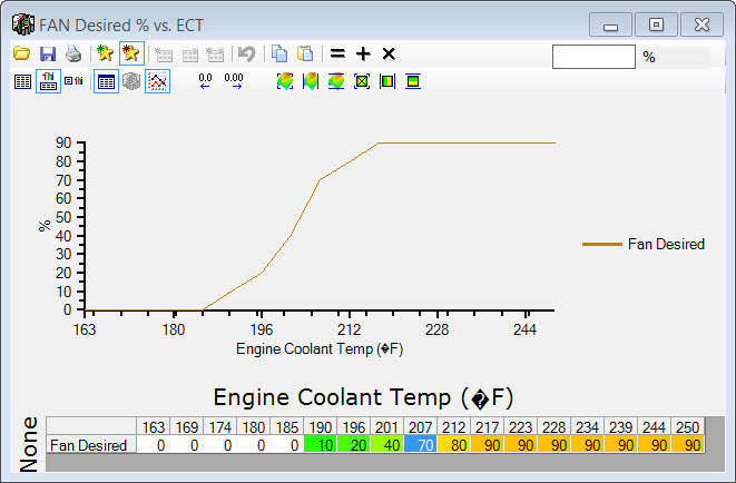
Hat tip to samckitt:
http://www.lateral-g.net/forums/show...=40215&page=25
Then I fired it up and watched the temp. It stabilized at 193/194 degrees just sitting there idling in the garage. At that temperature the fan is only at 40%, which means it can sit there forever. I am really pleased with how the coolant system and the fan controller worked on on this build.
Andrew
06-16-2015, 04:01 PM
#498
TECH Senior Member
Thread Starter
iTrader: (7)
Went to check out a local shop that claims to do custom exhaust. I talked to them a bit and I think I am going to have them do the exhaust on the Cougar. The exhaust is pretty straightforward, so how badly can they mess up? LOL
I also asked them if they can tweak my shifter handle a little bit to bring it back some. He didn't blink and just told me to come on back. Stuck it in his exhaust bender and after a few taps, I was good to go. He earned my business with that little gesture.
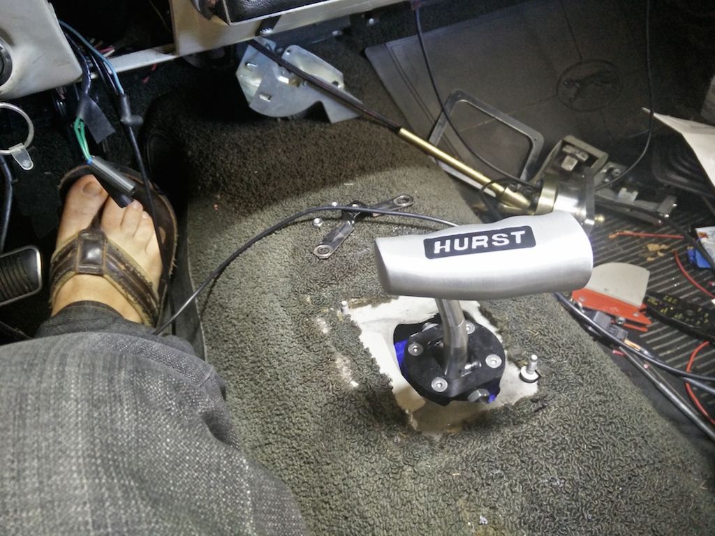
Note: if you have a second hand B&M Ripper shifter, don't loose those fancy little offset washers. B&M will not sell you any sort of service parts. I called them and offered to buy the parts, and all they said was that they don't encourage the second hand sale of their products and will not sell any service parts. I even talked to the manager on duty, but all he did was offer to sell me a new shifter for $190, but I declined. This is the kind of BS that happens when some big company buy up little companies. Needless to say I won't be buying any new B&M, Hurst, or Flowmaster products.
Andrew
I also asked them if they can tweak my shifter handle a little bit to bring it back some. He didn't blink and just told me to come on back. Stuck it in his exhaust bender and after a few taps, I was good to go. He earned my business with that little gesture.
Note: if you have a second hand B&M Ripper shifter, don't loose those fancy little offset washers. B&M will not sell you any sort of service parts. I called them and offered to buy the parts, and all they said was that they don't encourage the second hand sale of their products and will not sell any service parts. I even talked to the manager on duty, but all he did was offer to sell me a new shifter for $190, but I declined. This is the kind of BS that happens when some big company buy up little companies. Needless to say I won't be buying any new B&M, Hurst, or Flowmaster products.
Andrew
06-19-2015, 10:58 PM
#499
TECH Senior Member
Thread Starter
iTrader: (7)
Not a lot to report visually, but today was a big day. I rolled the car out of the garage and did a bit clean-up job in the garage. It was a gorgeous day and it was nice to see the car out in the driveway for the first time.
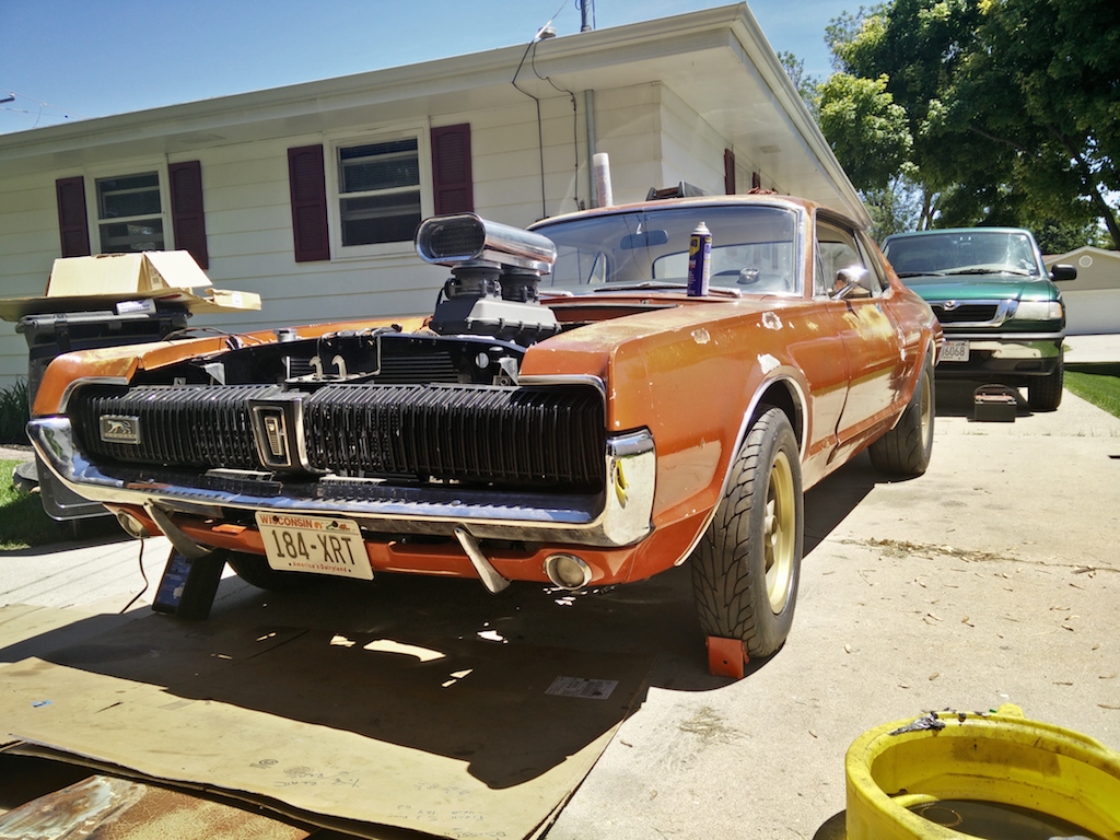
As you can see, I also got plates for the car and it will be insured Monday, so I am getting ready for the day when it can move under its own power. Just waiting for the driveshaft. Frank at the Driveshaft Shop is working on a dual CV carbon shaft.
While the car was out I got the bright idea that it was the perfect time to bleed the brakes. I started by bleeding the MC first, then I moved to getting some fluid through the system to the rear brakes. It didn't take long before I looked under the car and saw three puddles at various points. I got under the car a luckily the leaks were happening from fittings that I neglected to tighten. Doh! After about 3 hours and working the various corners for 3 hours I was able to get a solid pedal. At this point I am pretty certain I have brakes.
After I cleared out the garage and got the crap off the car I rolled it back inside and measured the ride height in the front. The driver's side is about 1/2" higher then the passenger side at rest, but once I sit in the car it levels out. I like the ride height. The front is about the same in the front as it is in the rear.
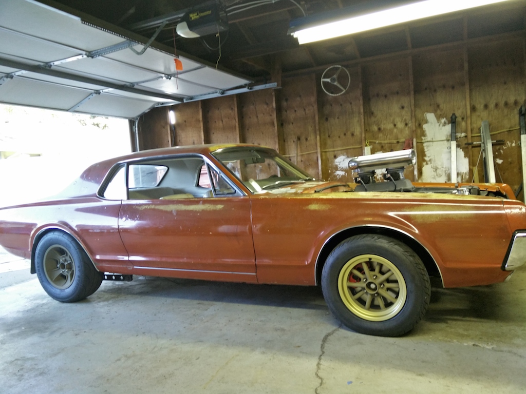
Once the car was inside, I thought it was a good time to start cleaning the interior a bit. It's funny how cars of similar vintage are put together in similar ways. The rear seat on the Cougar comes out exactly the same way as the rear seat in my GTO. A little push and shove and a couple of bolts later, the rear cushion and seat back were out.
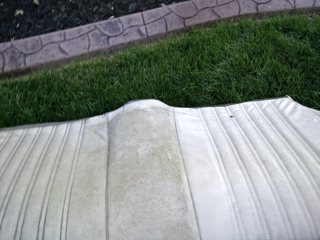
I got a brush, a hose, some Dawn, and went to work. The seats cleaned up very nicely. You can see the cleaned side on the right.
I also wiped the whole car down with WD40, because I am classy like that.
Andrew
As you can see, I also got plates for the car and it will be insured Monday, so I am getting ready for the day when it can move under its own power. Just waiting for the driveshaft. Frank at the Driveshaft Shop is working on a dual CV carbon shaft.
While the car was out I got the bright idea that it was the perfect time to bleed the brakes. I started by bleeding the MC first, then I moved to getting some fluid through the system to the rear brakes. It didn't take long before I looked under the car and saw three puddles at various points. I got under the car a luckily the leaks were happening from fittings that I neglected to tighten. Doh! After about 3 hours and working the various corners for 3 hours I was able to get a solid pedal. At this point I am pretty certain I have brakes.
After I cleared out the garage and got the crap off the car I rolled it back inside and measured the ride height in the front. The driver's side is about 1/2" higher then the passenger side at rest, but once I sit in the car it levels out. I like the ride height. The front is about the same in the front as it is in the rear.
Once the car was inside, I thought it was a good time to start cleaning the interior a bit. It's funny how cars of similar vintage are put together in similar ways. The rear seat on the Cougar comes out exactly the same way as the rear seat in my GTO. A little push and shove and a couple of bolts later, the rear cushion and seat back were out.
I got a brush, a hose, some Dawn, and went to work. The seats cleaned up very nicely. You can see the cleaned side on the right.
I also wiped the whole car down with WD40, because I am classy like that.
Andrew
06-20-2015, 01:06 PM
#500

Looks great Andrew. You get alot done in a short time like Ken (Kwhizz). If you ever need to clean anything again, try LA"s totally AWSOME. We have it locally at Dollar General for $1 in a spray ior $3 for a gallon jug. This stuff is AMAZING.
Do you plan on going for the 1st LS powered ride this summer?
Do you plan on going for the 1st LS powered ride this summer?