
1967 Cougar build (over 500 pictures and videos)
 09-17-2023, 02:12 PM
#1281
TECH Senior Member
Thread Starter
iTrader: (7)

Before moving on with the fan and radiator, I figure I would share the parts needed for the LSA supercharger drive. I bought a new water pump for a ZL1 Camaro. It has the correct spacing for the water pump and the holes that are needed for the blower drive idler pulleys.
I also got a new 6 rib belt tensioner and pulley. It bolts to an existing boss on the water pump.
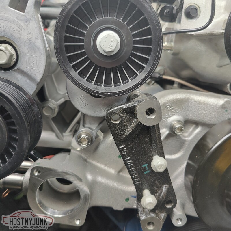
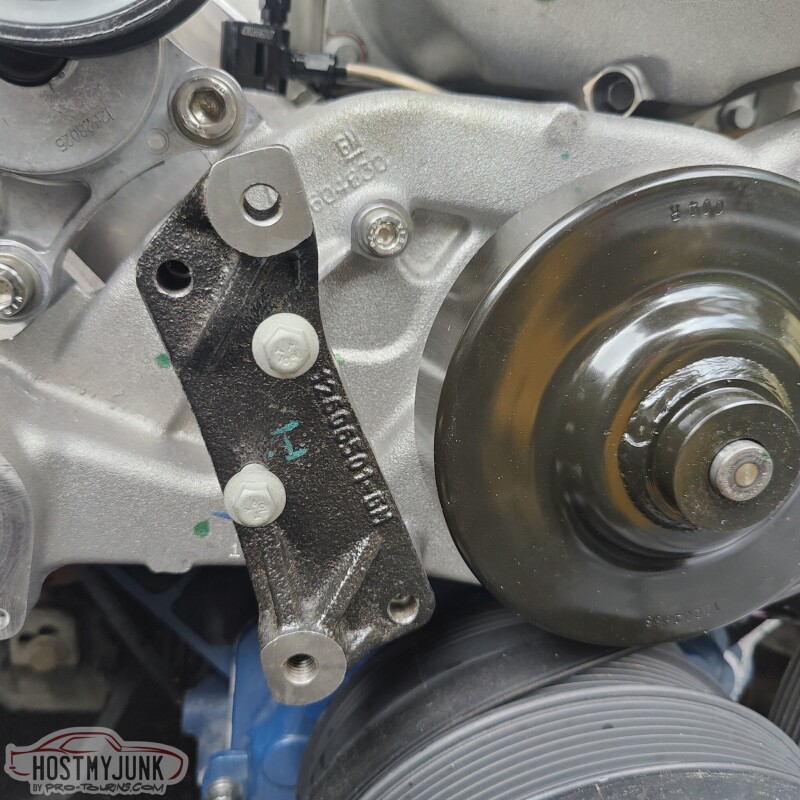
This is the blower tensioner pulley, and it bolts to the front of the passenger side head as well as having a bolt that goes into the water pump.
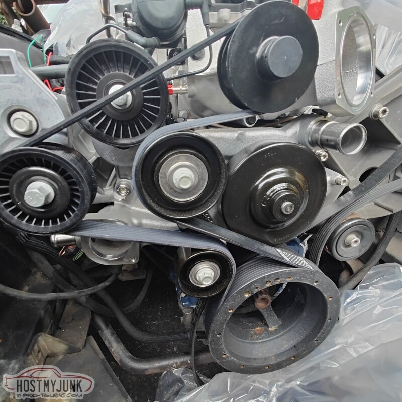
Here is the complete supercharger drive system, fully installed.
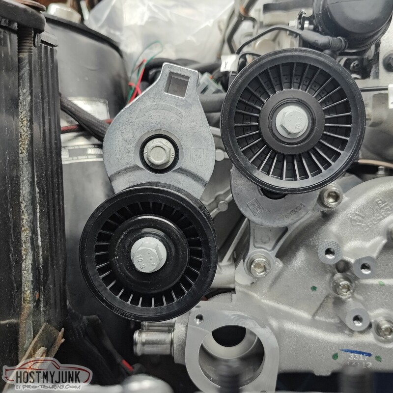
There is a mark on the tensioner and it seems perfect right there.
Andrew
I also got a new 6 rib belt tensioner and pulley. It bolts to an existing boss on the water pump.
This is the blower tensioner pulley, and it bolts to the front of the passenger side head as well as having a bolt that goes into the water pump.
Here is the complete supercharger drive system, fully installed.
There is a mark on the tensioner and it seems perfect right there.
Andrew

The following users liked this post:
kwhizz (09-19-2023)
09-17-2023, 02:30 PM
#1282
TECH Senior Member
Thread Starter
iTrader: (7)
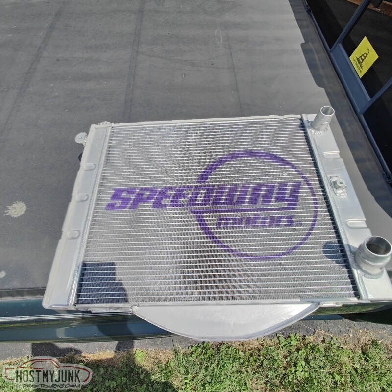
I handed the new radiator and fan to Vic and asked him to make it all fit...LOL
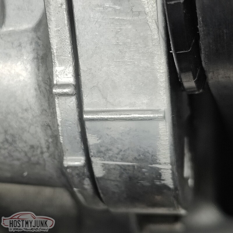
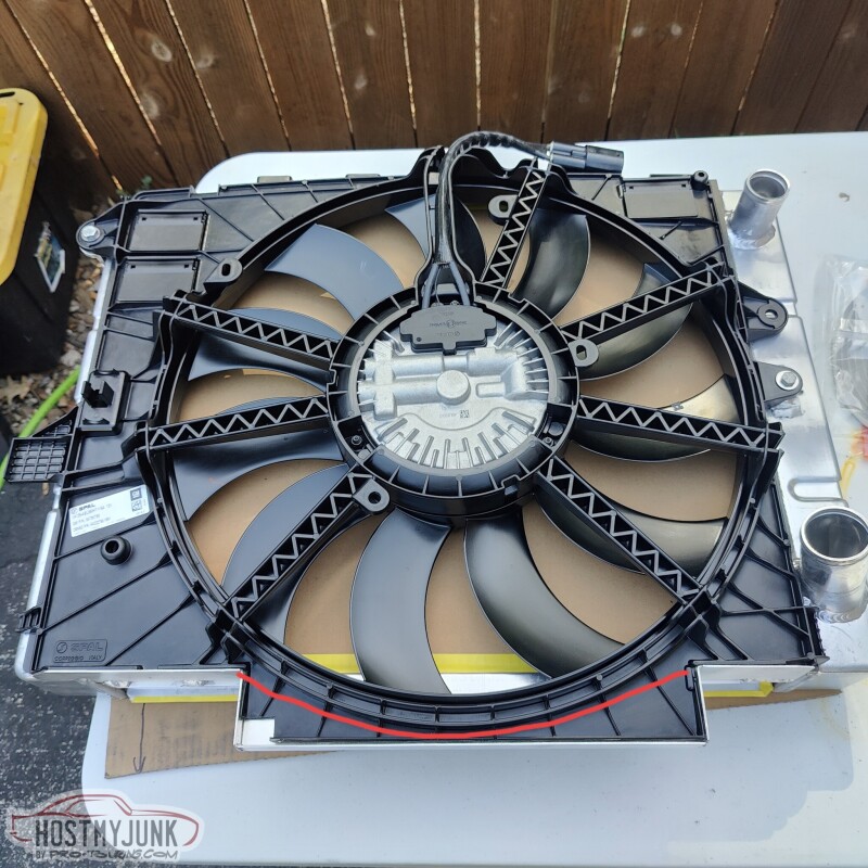
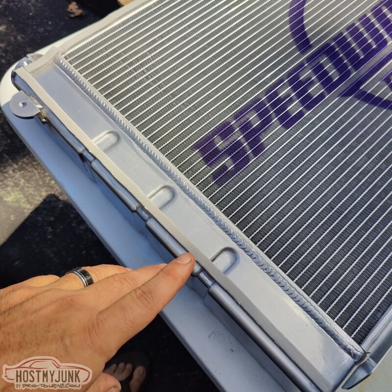
This was his first iteration. He has the fan mounted to the radiator with some tabs that were welded to the tanks. This is the driver's side bracket...
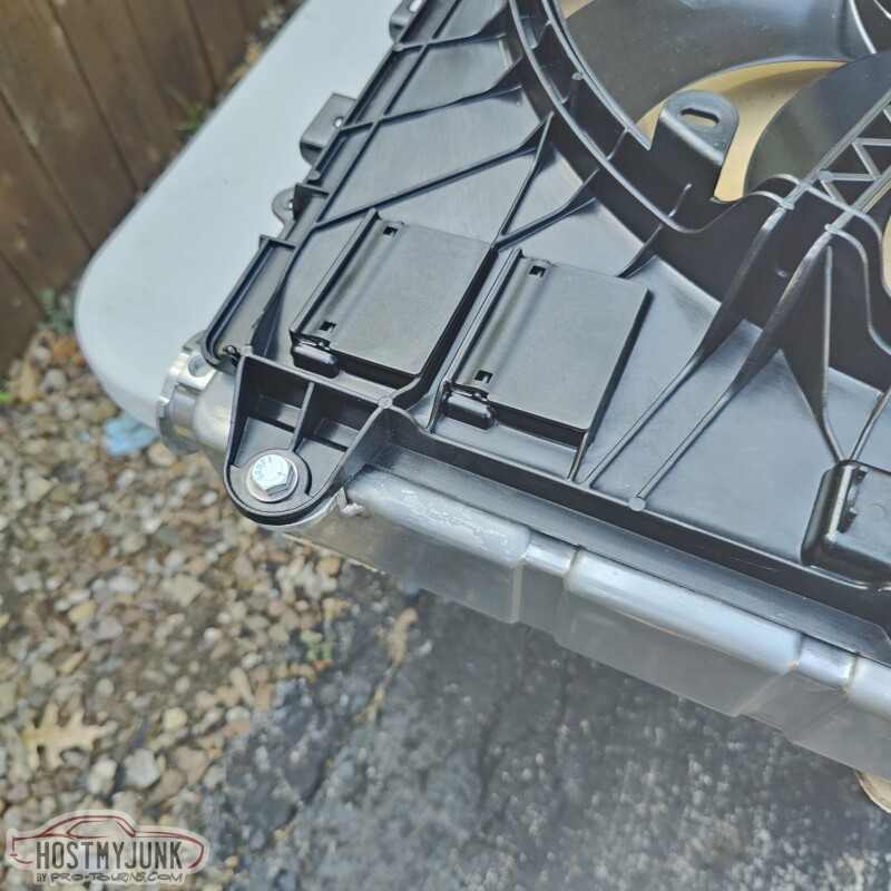
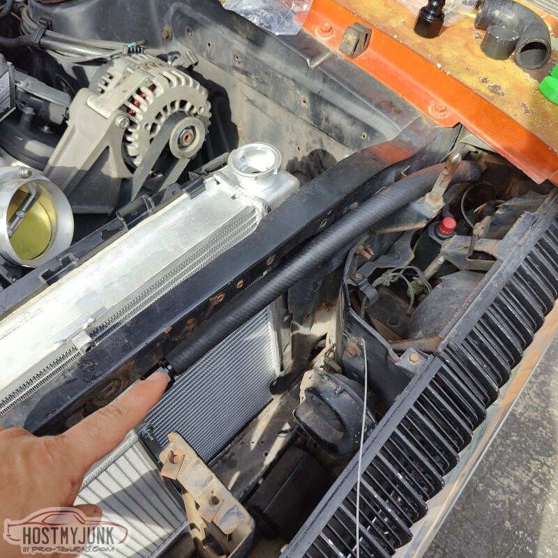
Here you can also see the bolt on the passenger side. The red line that is drawn on the picture is what ultimately happened. I trimmed the shroud to follow the curve of the fan blades and Vic then added a little curved aluminum piece to keep the blades protected from road debris, etc...
The fan shroud has these mounting tabs at the top...
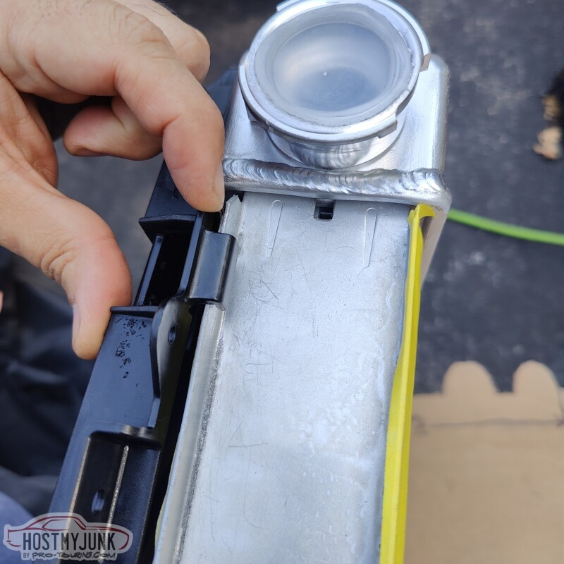
You can see that they clip perfectly over the radiator core header panel.
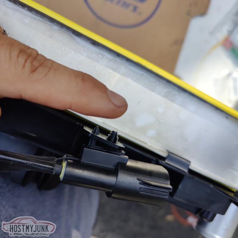
I added some thin foam along the side of the driver's side tank and also along the top.
This is to seal the shroud against the top and sides of the radiator...
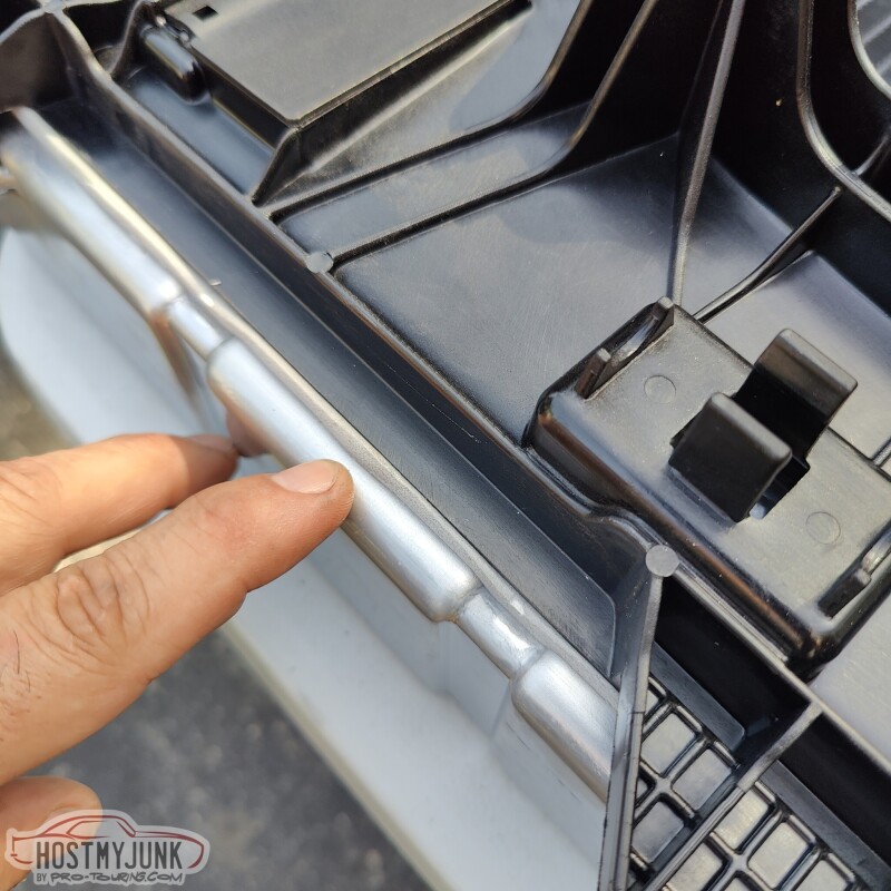
as well as the keep the fan from vibrating...just in case...
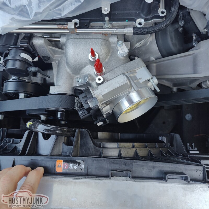
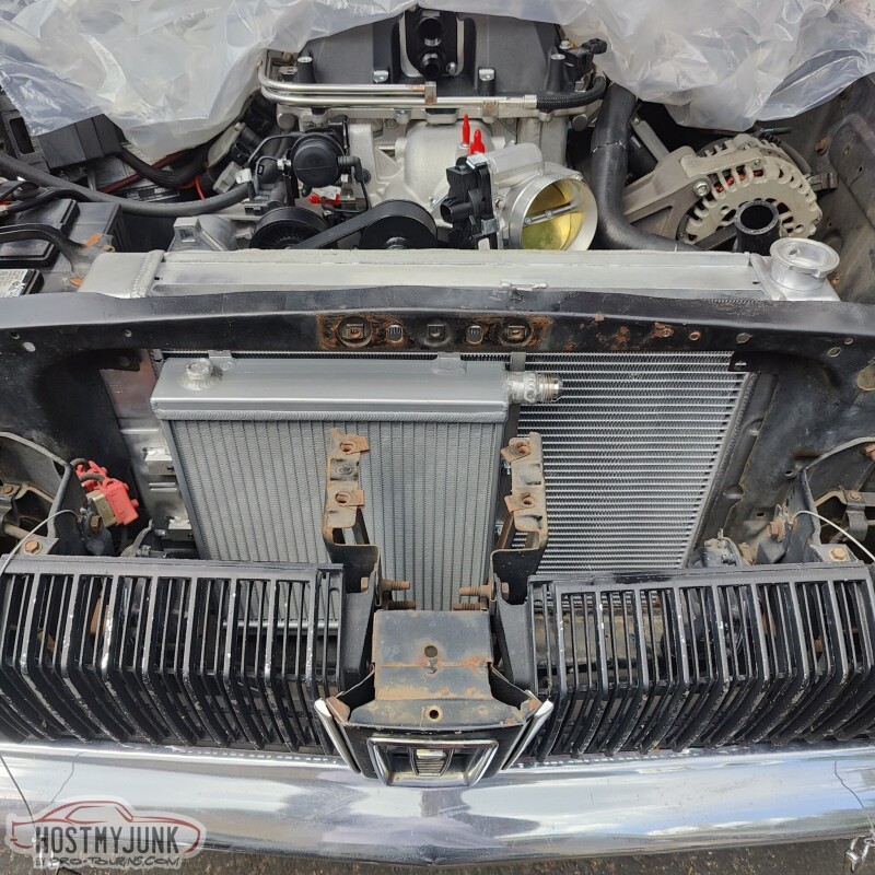
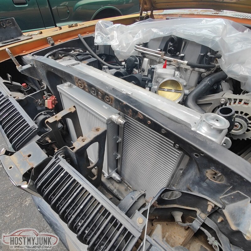
I dropped the radiator and fan assembly into the car and as you can see, it is a pretty tight fit. There is a lot less room between the throttle body and the radiator than compared to a 1st Gen Camaro. You can also see the two plugs from ICT Billet on the blower snout.
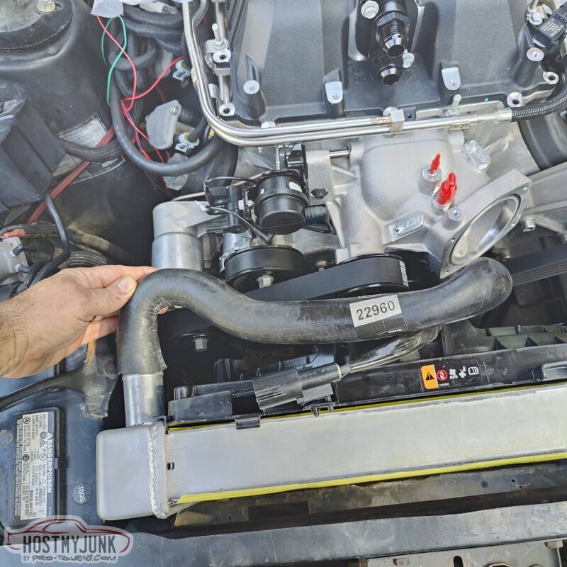
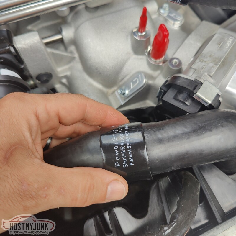
This is the part number of the upper radiator hose that I used, although I modified it extensively.
Looking at the hose, I realized that I can use all of it, but it needed to be cut and the hose rotated 90 degrees in two places. The first cit needs to be right along where the decal with the part number is...
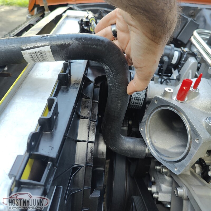
The second cut is right where my thumb is.
More to come...
Andrew
This was his first iteration. He has the fan mounted to the radiator with some tabs that were welded to the tanks. This is the driver's side bracket...
Here you can also see the bolt on the passenger side. The red line that is drawn on the picture is what ultimately happened. I trimmed the shroud to follow the curve of the fan blades and Vic then added a little curved aluminum piece to keep the blades protected from road debris, etc...
The fan shroud has these mounting tabs at the top...
You can see that they clip perfectly over the radiator core header panel.
I added some thin foam along the side of the driver's side tank and also along the top.
This is to seal the shroud against the top and sides of the radiator...
as well as the keep the fan from vibrating...just in case...
I dropped the radiator and fan assembly into the car and as you can see, it is a pretty tight fit. There is a lot less room between the throttle body and the radiator than compared to a 1st Gen Camaro. You can also see the two plugs from ICT Billet on the blower snout.
This is the part number of the upper radiator hose that I used, although I modified it extensively.
Looking at the hose, I realized that I can use all of it, but it needed to be cut and the hose rotated 90 degrees in two places. The first cit needs to be right along where the decal with the part number is...
The second cut is right where my thumb is.
More to come...
Andrew
The following 3 users liked this post by Project GatTagO:
09-18-2023, 09:55 PM
#1283
TECH Senior Member
Thread Starter
iTrader: (7)
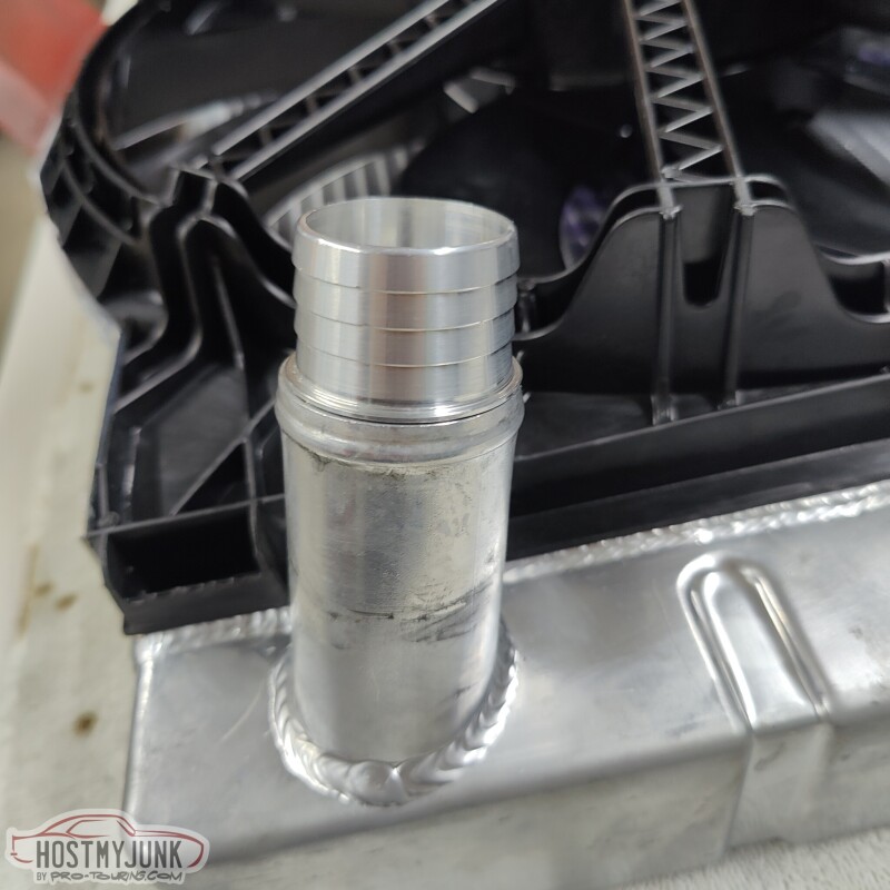
These little gems from ICT Billet are actually made to be used as radiator hose reducers. They can be cut in half and one used for the upper radiator hose and the other for the lower radiator hose.
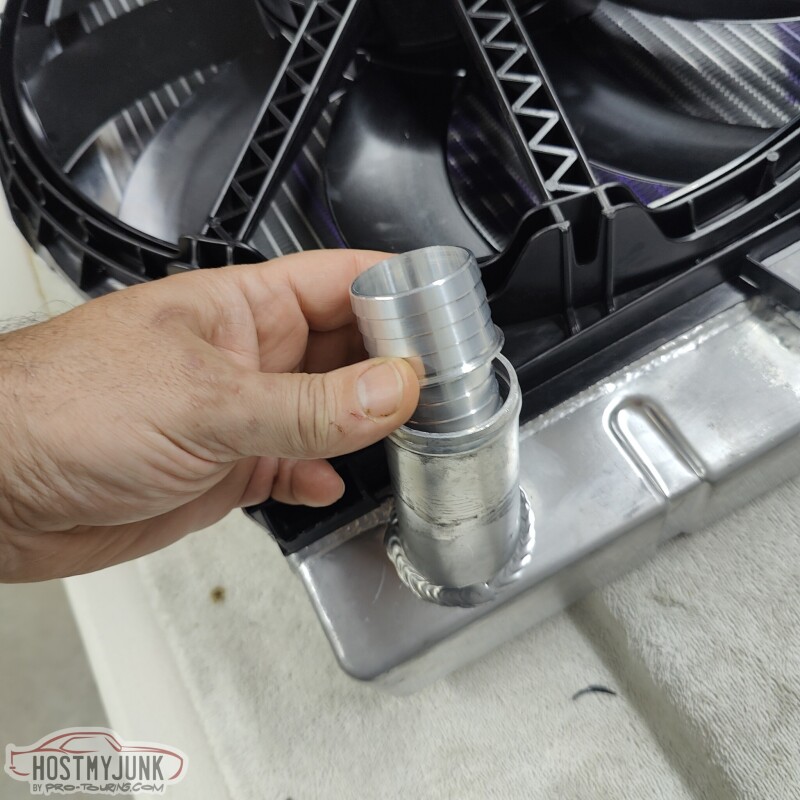
This makes adapting hoses to LS engines a lot easier. I had Vic weld this to the outlet on the new radiator.
Here you can see where I made one cut in the hose and used an ICT Billet coupler to put the hose back together, but now the hose is rotated 90 degrees.
Here is the other cut, splice and re-clock of the hose. I later used the Gates heat shrink hose clamps to clamp the hose to the couplers. Doing this basically turns it into a new custom hose.
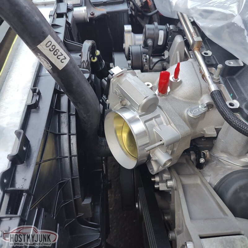
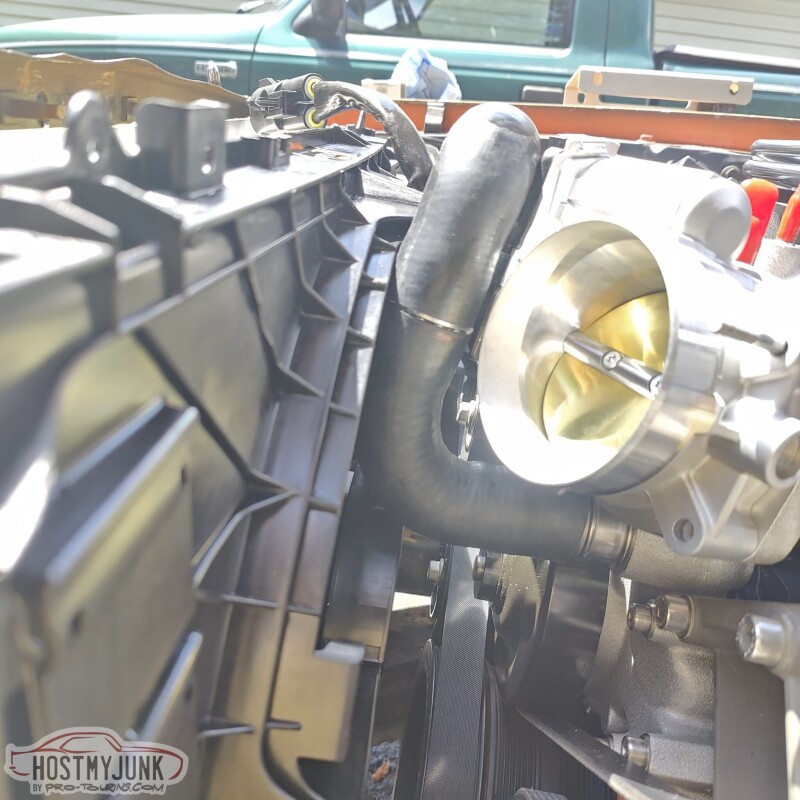
Here you can see how nicely the hose clears the throttle body and the fan shroud. In fact, the fan shroud has a cutout precisely at the spot where the hose needs to go.
I am also holding what hopefully will become the start for the intake tube. This is a quarter of a 4" diameter donut. It was left over from doing the intake charge pipe for the GTO project.
You can see how the tight bend allows the 4" pipe to clear the fan shroud.
This piece will have to be carefully miter cut and a straight portion welded to it, but it is a start.
Andrew
This makes adapting hoses to LS engines a lot easier. I had Vic weld this to the outlet on the new radiator.
Here you can see where I made one cut in the hose and used an ICT Billet coupler to put the hose back together, but now the hose is rotated 90 degrees.
Here is the other cut, splice and re-clock of the hose. I later used the Gates heat shrink hose clamps to clamp the hose to the couplers. Doing this basically turns it into a new custom hose.
Here you can see how nicely the hose clears the throttle body and the fan shroud. In fact, the fan shroud has a cutout precisely at the spot where the hose needs to go.
I am also holding what hopefully will become the start for the intake tube. This is a quarter of a 4" diameter donut. It was left over from doing the intake charge pipe for the GTO project.
You can see how the tight bend allows the 4" pipe to clear the fan shroud.
This piece will have to be carefully miter cut and a straight portion welded to it, but it is a start.
Andrew
The following 3 users liked this post by Project GatTagO:
09-21-2023, 03:11 PM
#1284
TECH Senior Member
Thread Starter
iTrader: (7)
Here are some pictures of various fittings that I was playing around with for the supercharger lid:
That bulky block with the cap and port is from LSx Innovations and it is designed to be a fill/bleeder for the supercharger intercooler.
I honestly done remember which fittings I ended up using, but we will find out when I get to that part.
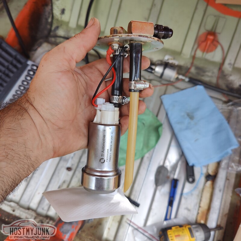
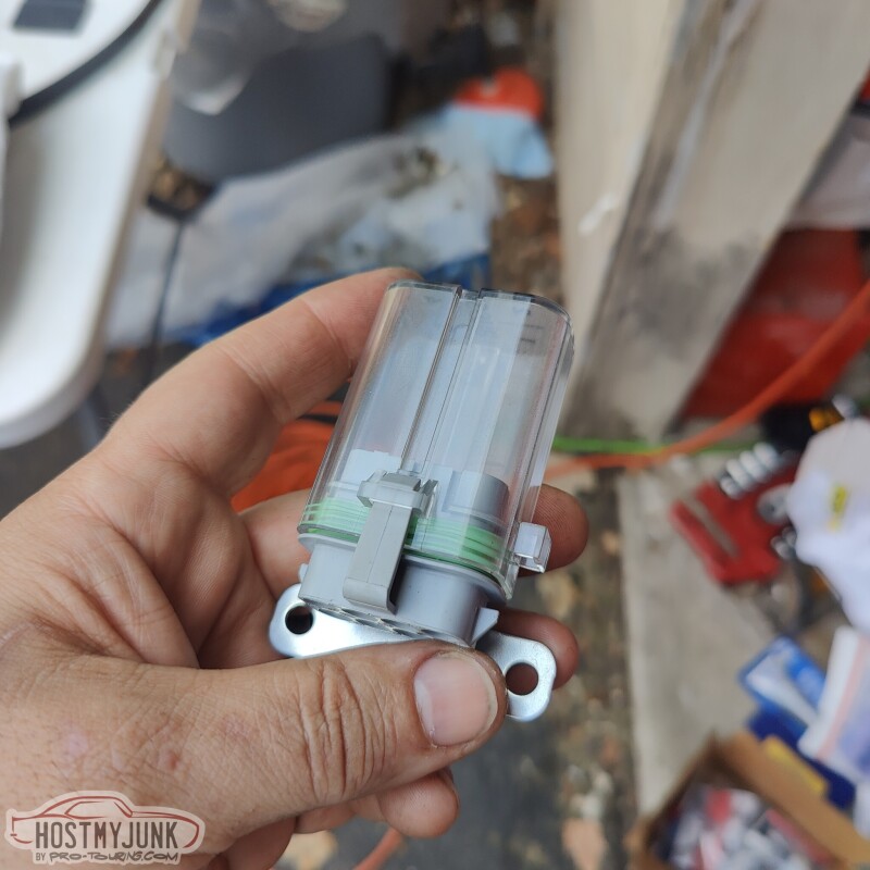
This is the new fuel pump. I got it because that is what Carl from VaporWorx recommended.
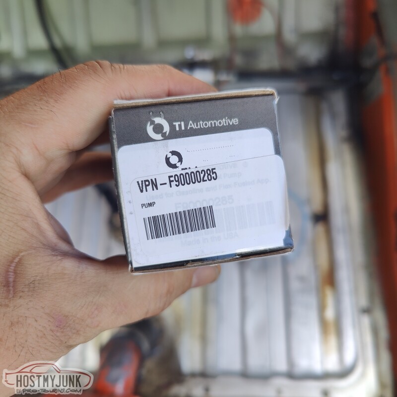
I was originally going to install a full VaporWorx system, but time was getting short and I needed a quick solution that didn't require a lot of plumbing or wiring changes. I am keeping the basic "pump on a stick" and I am even keeping the Wix Corvette regulator/filter. I will handle the boost compensation for fuel another way.
This is the heat exchanger for the intercooler. It is an inexpensive unit from frozenboost.com
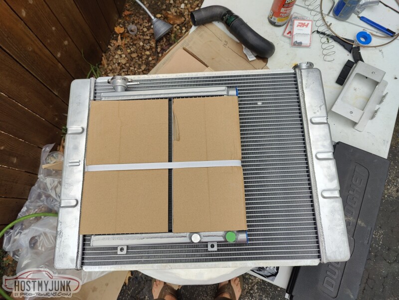
It will get modified and fitted to the radiator.
Andrew
That bulky block with the cap and port is from LSx Innovations and it is designed to be a fill/bleeder for the supercharger intercooler.
I honestly done remember which fittings I ended up using, but we will find out when I get to that part.
This is the new fuel pump. I got it because that is what Carl from VaporWorx recommended.
I was originally going to install a full VaporWorx system, but time was getting short and I needed a quick solution that didn't require a lot of plumbing or wiring changes. I am keeping the basic "pump on a stick" and I am even keeping the Wix Corvette regulator/filter. I will handle the boost compensation for fuel another way.
This is the heat exchanger for the intercooler. It is an inexpensive unit from frozenboost.com
It will get modified and fitted to the radiator.
Andrew
09-21-2023, 03:32 PM
#1285

Here are some pictures of various fittings that I was playing around with for the supercharger lid:
That bulky block with the cap and port is from LSx Innovations and it is designed to be a fill/bleeder for the supercharger intercooler.
I honestly done remember which fittings I ended up using, but we will find out when I get to that part.
This is the new fuel pump. I got it because that is what Carl from VaporWorx recommended.
I was originally going to install a full VaporWorx system, but time was getting short and I needed a quick solution that didn't require a lot of plumbing or wiring changes. I am keeping the basic "pump on a stick" and I am even keeping the Wix Corvette regulator/filter. I will handle the boost compensation for fuel another way.
This is the heat exchanger for the intercooler. It is an inexpensive unit from frozenboost.com
It will get modified and fitted to the radiator.
Andrew
I'm using the holley retrofit now:
The following users liked this post:
kwhizz (09-22-2023)
09-21-2023, 04:14 PM
#1286
TECH Senior Member
Thread Starter
iTrader: (7)
Andrew
09-21-2023, 04:28 PM
#1287
TECH Senior Member
Thread Starter
iTrader: (7)
While Vic was working on mounting the heat exchanger to the radiator, I took a little detour to build new injector and coil harnesses.
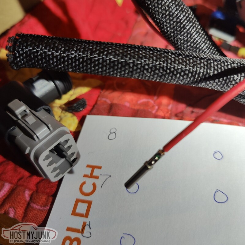
Normally, the Holley EFI harness would have the MetriPack 150 series connectors for the coils. When I first built the Cougar, I converted them to Deutsch connectors.
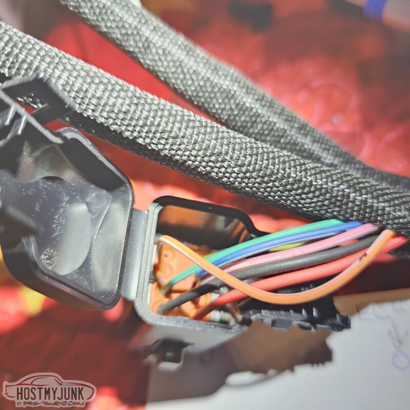
I used a 90 degree connector back to protect the wires and give them added strain relief.
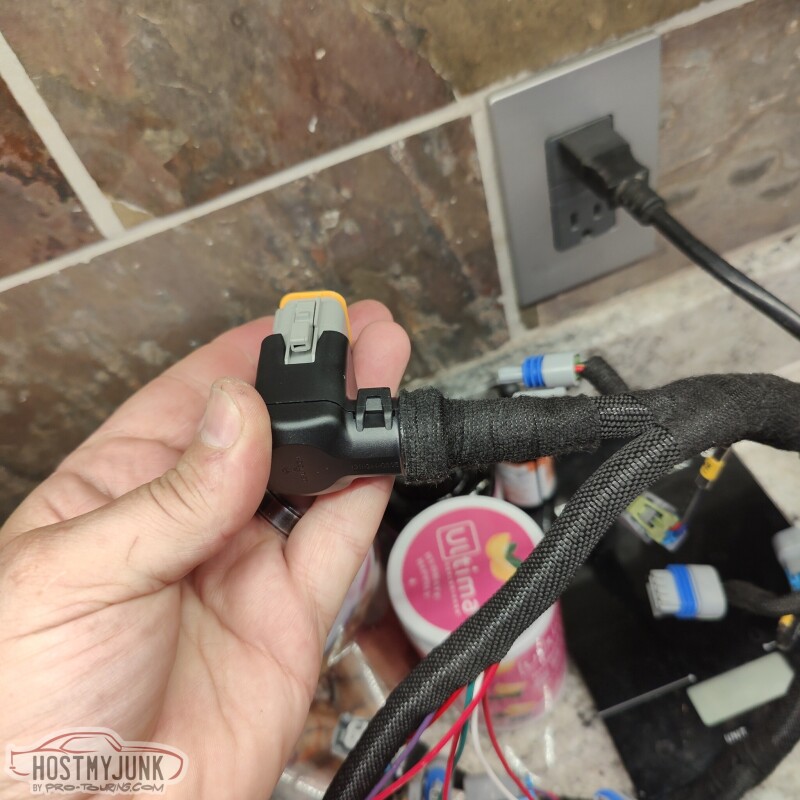
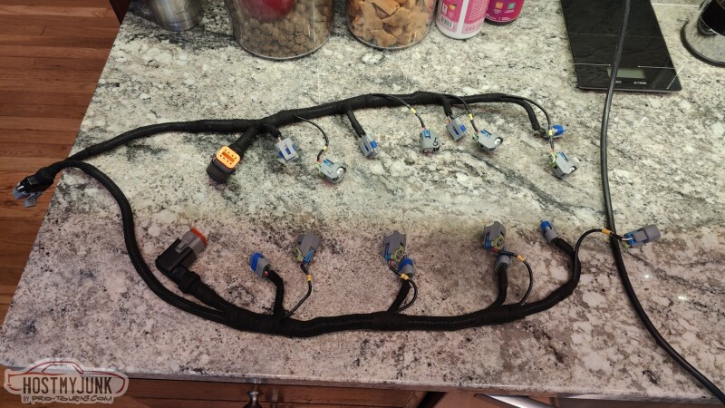
Holley also keeps their injector and coil harnesses separate, but I ran them all together for a cleaner look. I also added some quick labels to the injector connectors.
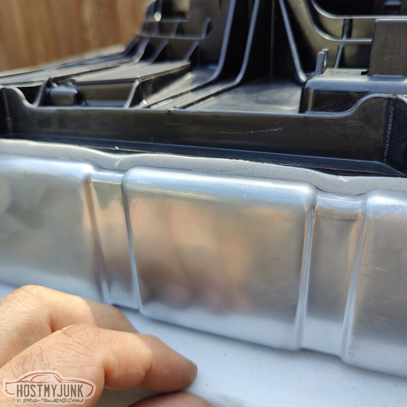
Vic finished up the installation of the heat exchanger on the radiator.
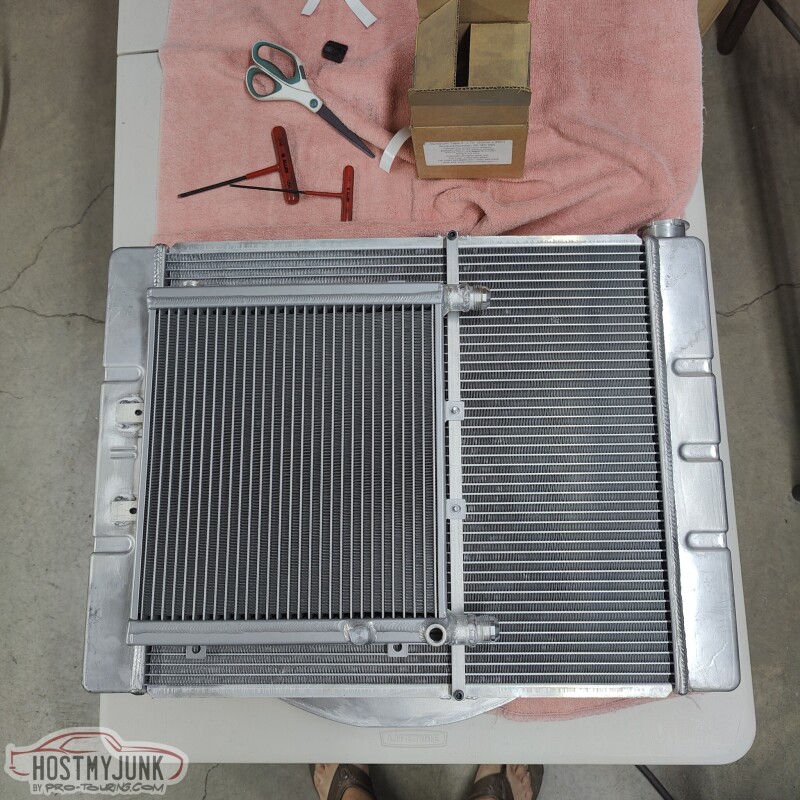
Here you can see the finished version of the bottom extension to protect the fan.
Here you can see how I got rid of the hood latch to make a little more room. I already have hood pins, so the latch is mostly extraneous.
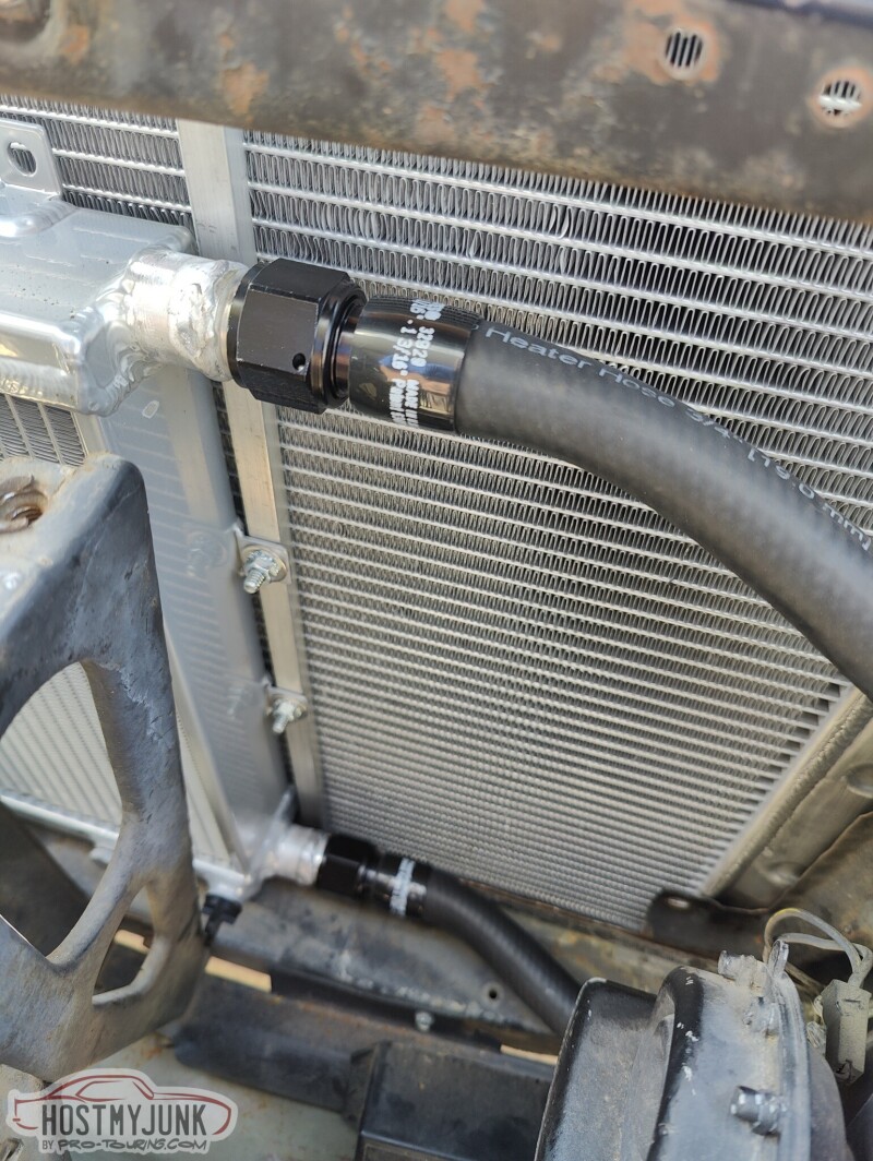
Vic also welded AN -12 male fittings to the heat exchanger so I can use AN hose ends.
Here you can see the regular 3/4" regular heater hose on an Earl's push lock fitting. I will use the gates heat shrink clamps on these for a clean look.
More to come...
Andrew
Normally, the Holley EFI harness would have the MetriPack 150 series connectors for the coils. When I first built the Cougar, I converted them to Deutsch connectors.
I used a 90 degree connector back to protect the wires and give them added strain relief.
Holley also keeps their injector and coil harnesses separate, but I ran them all together for a cleaner look. I also added some quick labels to the injector connectors.
Vic finished up the installation of the heat exchanger on the radiator.
Here you can see the finished version of the bottom extension to protect the fan.
Here you can see how I got rid of the hood latch to make a little more room. I already have hood pins, so the latch is mostly extraneous.
Vic also welded AN -12 male fittings to the heat exchanger so I can use AN hose ends.
Here you can see the regular 3/4" regular heater hose on an Earl's push lock fitting. I will use the gates heat shrink clamps on these for a clean look.
More to come...
Andrew
The following 3 users liked this post by Project GatTagO:
09-21-2023, 04:32 PM
#1288
Curious on your details as I do have Holley efi!
09-21-2023, 09:24 PM
#1289
TECH Senior Member
Thread Starter
iTrader: (7)
Apparently I am on a roll today...
I was going to build a harness for the fan, but instead I ordered this kit from Vintage Air. This is the wiring kit that they include with their "Monster" fan kits, which use basically the same fan that I am using.
The harness is made with 6 gauge wire, the fan connector is terminated (this was a concern for me at home), and it includes a Mega fuse holder with a 100amp fuse.
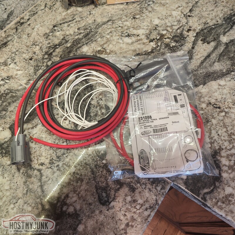
I used Raychem DR-25 to fully encase the fan wires, just to give them an extra layer of protection. It also keeps the small signal wire in the loom.
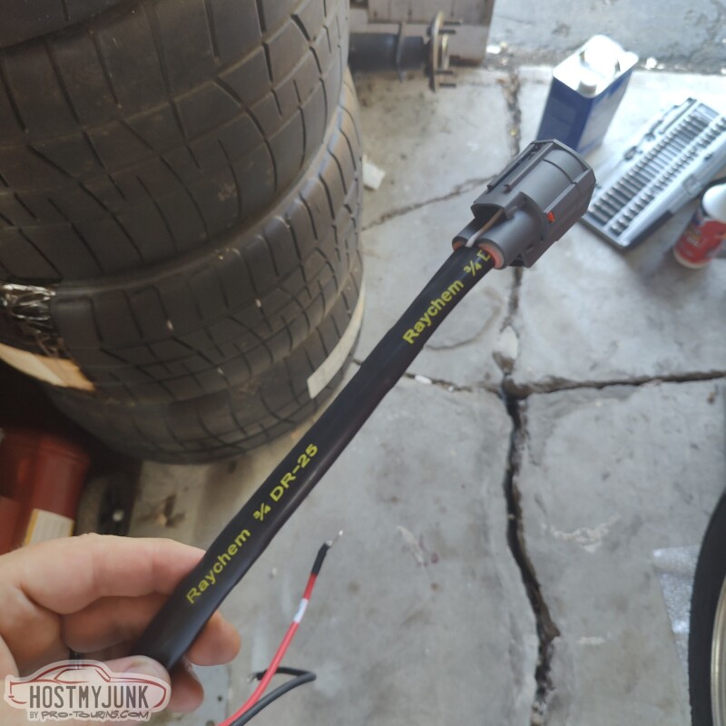
This is the fuse holder with the fuse already installed. I actually fully sheathed the fuse holder in Raychem. The odds of that fuse blowing are very small, barring a major disaster or epic dumbassery...
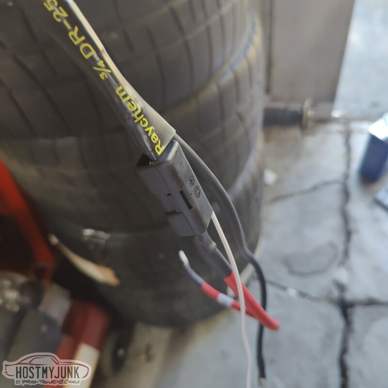
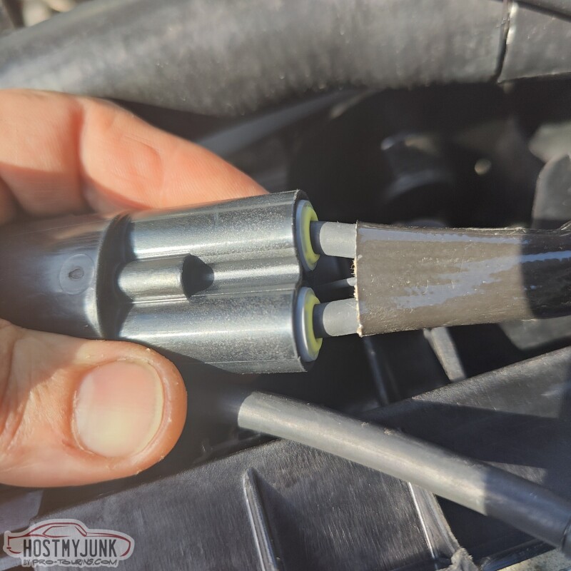
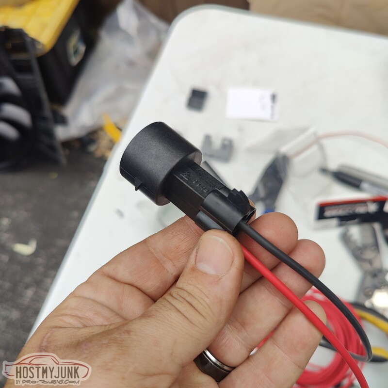
This is the fan side connector and wiring. I believe it too uses 6 gauge wire.
This is another picture of the fan harness and you can see the fuse holder with the heat shrink over it. This harness makes a few tight bends and twists around the radiator and the battery, so I wanted it well protected.
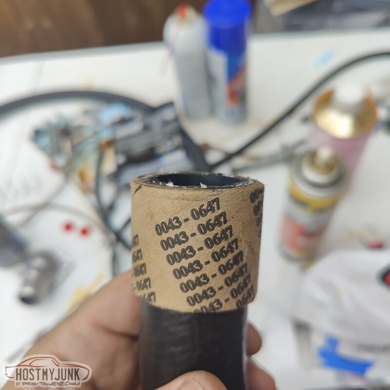
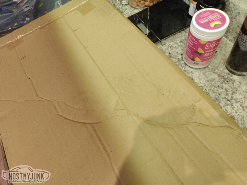
Here is a tip for trimming radiator hoses that aren't quite square. I use there cardboard tubes that originally held the Gates heat shrink clamps on them. You push the radiator hose through the sleeve...
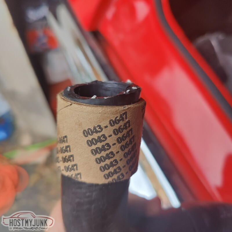
And use a sharp razor blade to trim the hose square.
With the hose ends squared, it was time to install the ICT Billet hose couplers for good.
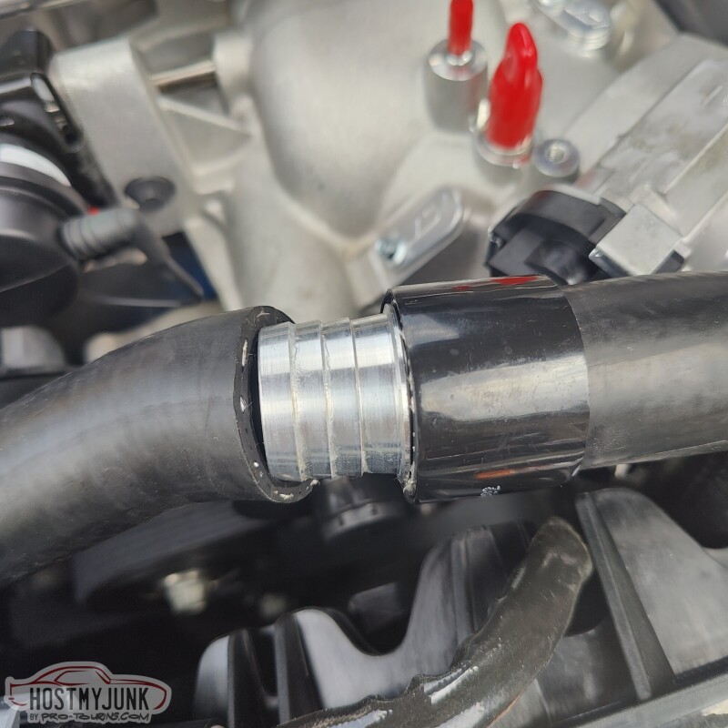
I used a single clamp to straddle the two hoses. The couplers have very aggressive barbs and a single clamp is more than enough to keep the joint water tight.
Next up was to wire the water pump for the supercharger. I am using a Pierburg CWA100-3 pump that I got from Tecomotive. This is a PWM capable pump so my original plan was to use the old fan power wiring. This connector already has direct battery power and a signal wire going back to the Dominator ECU.
This is a MetriPack 480 series connector and I happened to have another mating connector. This harness was supposed to go straight to the water pump. Unfortunately, when I hooked it up for testing, the pump would run at full speed when the ECU was powered down. This was something that I did not expect. I figured this pump would work like the fan.
So given the situation, I decided to use one of these LittleFuse ultra micro relay power centers. It uses Metripack 280 terminals and has the standard mini fuse spacing. It can house a mini fuse and a little relay.
So now, the trigger wire is used to turn on the water pump when the engine is running. That means that I had to run another wire from the I/O connector for the water pump signal wire. I did not document this, because it is not very exciting and a pain in the a$$.
That's it for today...
Andrew
I was going to build a harness for the fan, but instead I ordered this kit from Vintage Air. This is the wiring kit that they include with their "Monster" fan kits, which use basically the same fan that I am using.
The harness is made with 6 gauge wire, the fan connector is terminated (this was a concern for me at home), and it includes a Mega fuse holder with a 100amp fuse.
I used Raychem DR-25 to fully encase the fan wires, just to give them an extra layer of protection. It also keeps the small signal wire in the loom.
This is the fuse holder with the fuse already installed. I actually fully sheathed the fuse holder in Raychem. The odds of that fuse blowing are very small, barring a major disaster or epic dumbassery...
This is the fan side connector and wiring. I believe it too uses 6 gauge wire.
This is another picture of the fan harness and you can see the fuse holder with the heat shrink over it. This harness makes a few tight bends and twists around the radiator and the battery, so I wanted it well protected.
Here is a tip for trimming radiator hoses that aren't quite square. I use there cardboard tubes that originally held the Gates heat shrink clamps on them. You push the radiator hose through the sleeve...
And use a sharp razor blade to trim the hose square.
With the hose ends squared, it was time to install the ICT Billet hose couplers for good.
I used a single clamp to straddle the two hoses. The couplers have very aggressive barbs and a single clamp is more than enough to keep the joint water tight.
Next up was to wire the water pump for the supercharger. I am using a Pierburg CWA100-3 pump that I got from Tecomotive. This is a PWM capable pump so my original plan was to use the old fan power wiring. This connector already has direct battery power and a signal wire going back to the Dominator ECU.
This is a MetriPack 480 series connector and I happened to have another mating connector. This harness was supposed to go straight to the water pump. Unfortunately, when I hooked it up for testing, the pump would run at full speed when the ECU was powered down. This was something that I did not expect. I figured this pump would work like the fan.
So given the situation, I decided to use one of these LittleFuse ultra micro relay power centers. It uses Metripack 280 terminals and has the standard mini fuse spacing. It can house a mini fuse and a little relay.
So now, the trigger wire is used to turn on the water pump when the engine is running. That means that I had to run another wire from the I/O connector for the water pump signal wire. I did not document this, because it is not very exciting and a pain in the a$$.
That's it for today...
Andrew
The following users liked this post:
rkupon1 (09-27-2023)
09-23-2023, 09:00 AM
#1290
TECH Senior Member
Thread Starter
iTrader: (7)
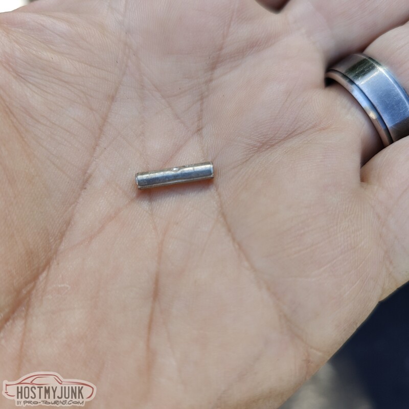
This may not be a super exciting update, but hopefully someone will benefit from it. Remember how I needed to run another wire for the water pump signal wire? Here is the process of how I make a butt splice for wiring. Generally I try to avoid doing butt splices, but obviously it can't always be avoided.
Here is the butt connector that I like to use. These are made by either 3M or Molex (I forget which) and they are available from Waytek Wire and I am sure many other vendors. I like using the non insulated butt connectors because they are the least bulky option. Also, when splicing multiple wires together in the same location, you want to stagger the butt splices to minimize the bulkiness in that one spot.
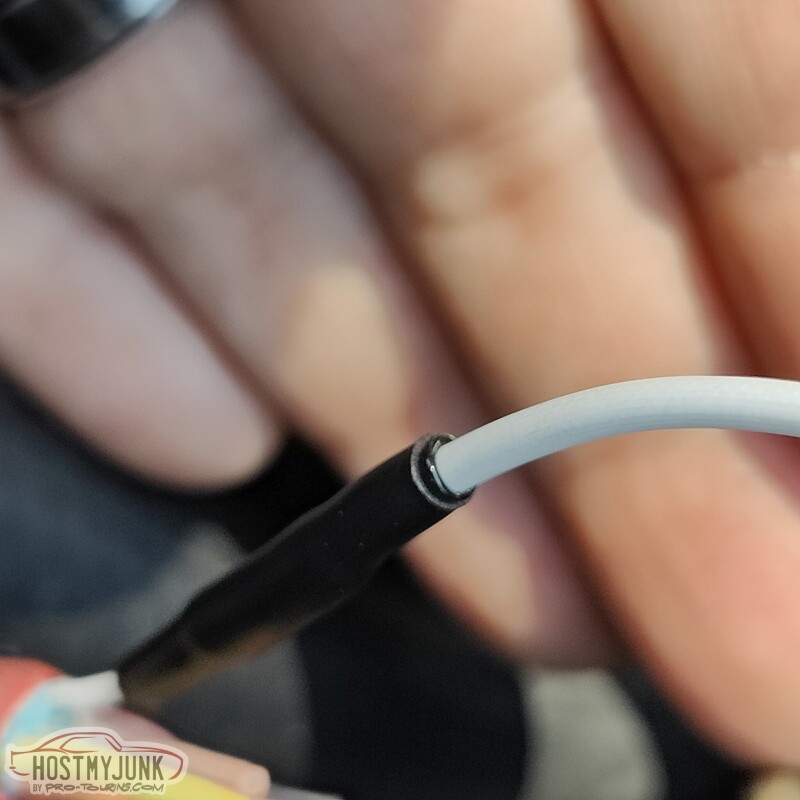
You want to strip the wire so a about half the width of the wire gauge is showing between the insulation and the butt connector. This is done for strain relief. Also notice the seam on the butt connector, this will be important when making the crimp.
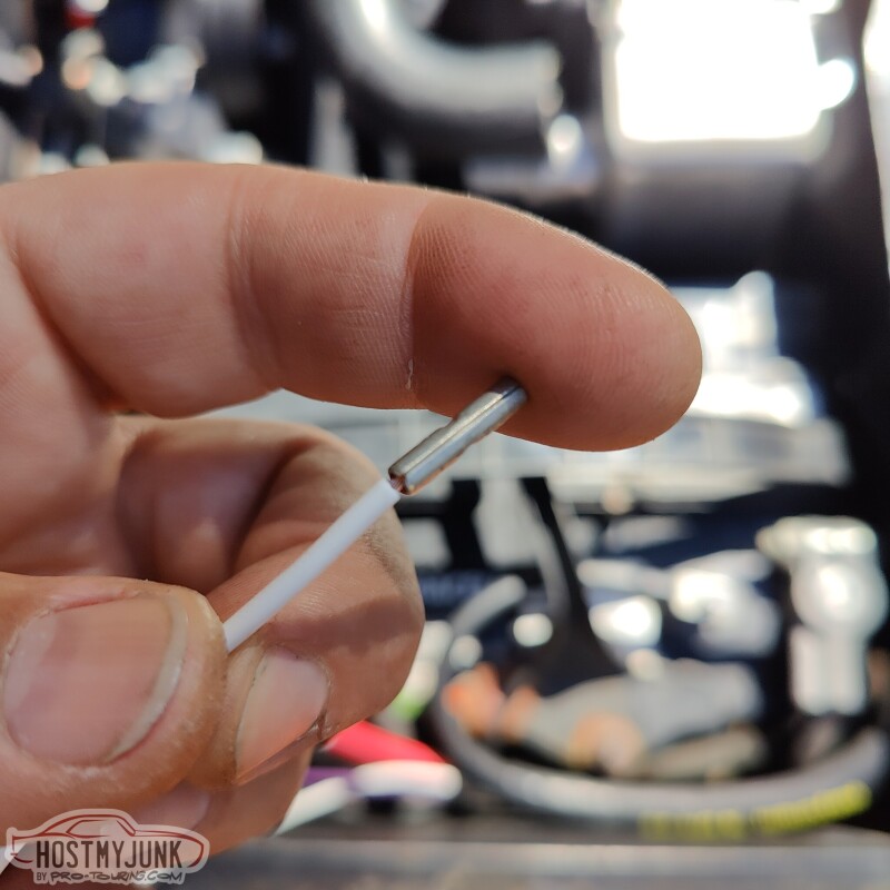
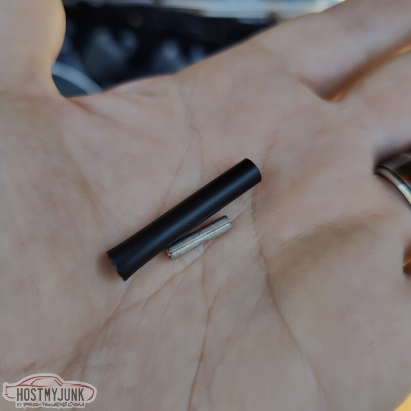
I use Raychem SCL heat shrink tubing for these kinds of connections. The SCL is very rigid and it has potting compound inside that will melt and seal the connection. I cut the length of the SCL to be about twice the length of the splice.
Make sure to remember that the heat shrink needs to go on before the final crimp is made.
This is the crimper tool that I use for these butt connectors. Make sure the seam is supported by the die on the back side.
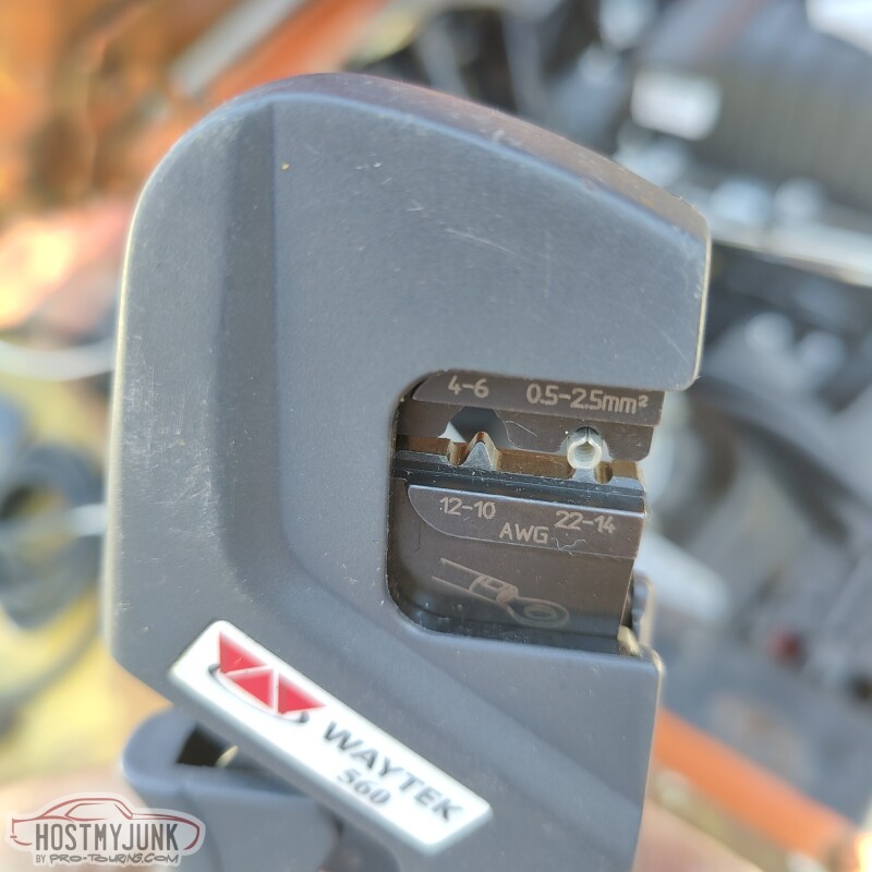
The crimper has a ratcheting mechanism that will not release until the crimper is squeezed a sufficient amount. It is important not to over-crimp as this will distort the butt connector.
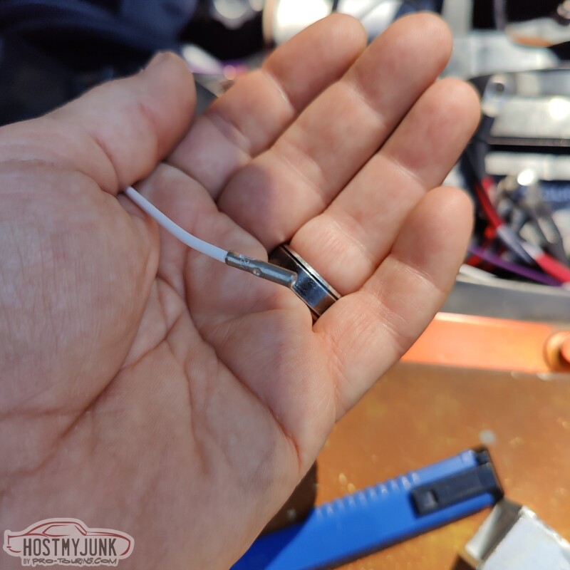
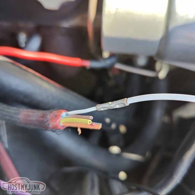
Here you can see both sides have been crimped. Also note what I am using for the actual wire. Instead of running a single wire through an existing loom, I re-used the 7 strand shielded cable that used to be for my second DBW throttle body. Using the shielded cable is not necessary, but it is much easier to run a length of it rather than a single wire conductor. It also leaves other conductors for future use.
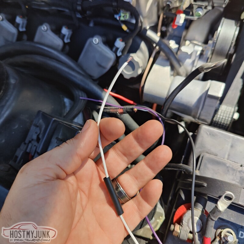
Here is the Raychem SCL after it was fully recovered. You can see the melted potting compound oozing out. This effectively seals that connection from any possible moisture.
Here is the finished loom. You can see that I added a purple and black wire to the harness. These are just spare wires for possible future use. Having 3 wires in a loom, instead of 1 makes it more durable.
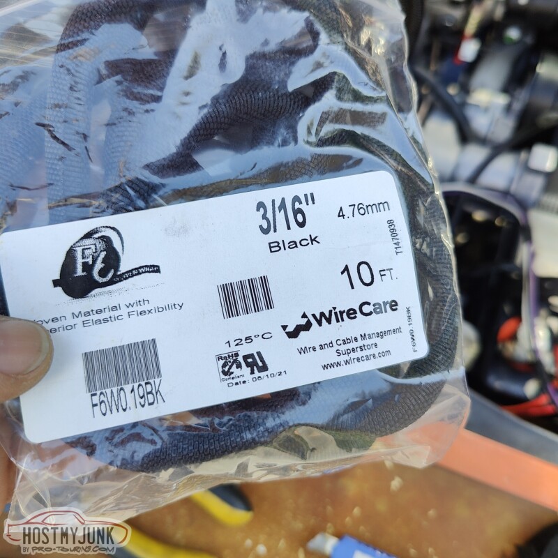
I used TechFlex F6 woven split loom to cover the harness. (somehow I do not have a picture of the finished loom).
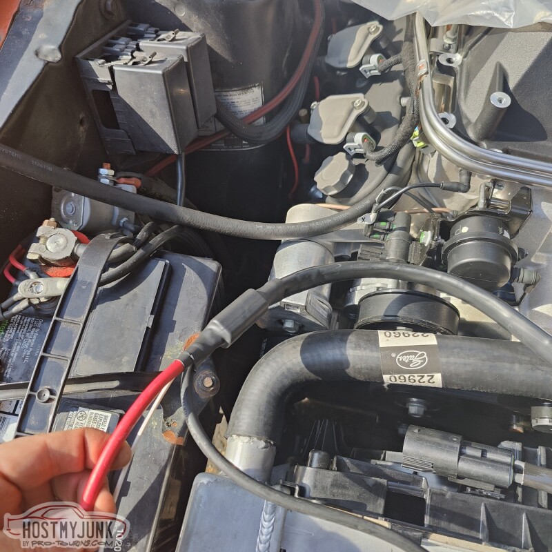
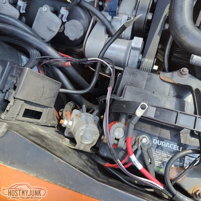
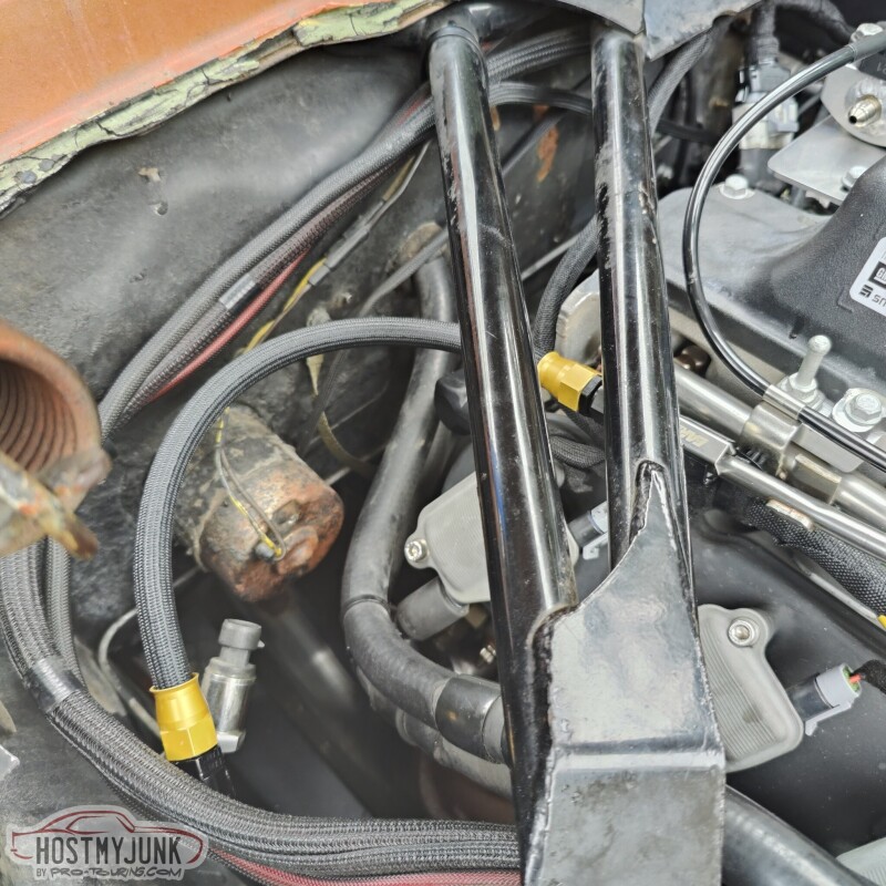
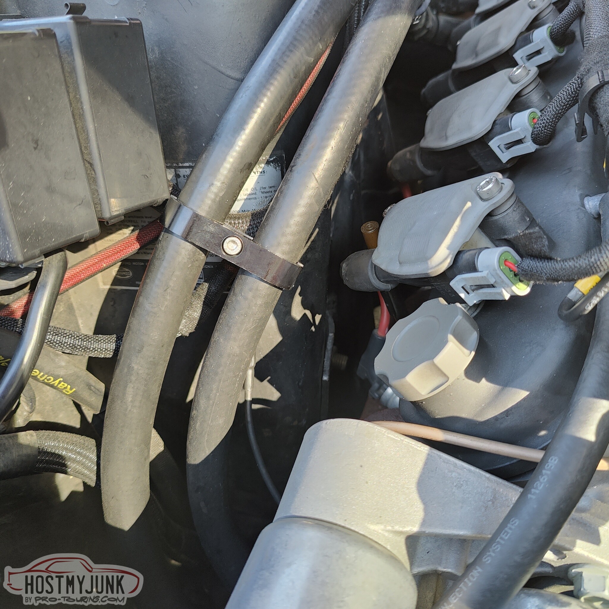
Here is another little trick that can turn a simple hose clamp into looking like a custom part. I took some heat shrink tubing and recovered it over this stainless hose clamp.
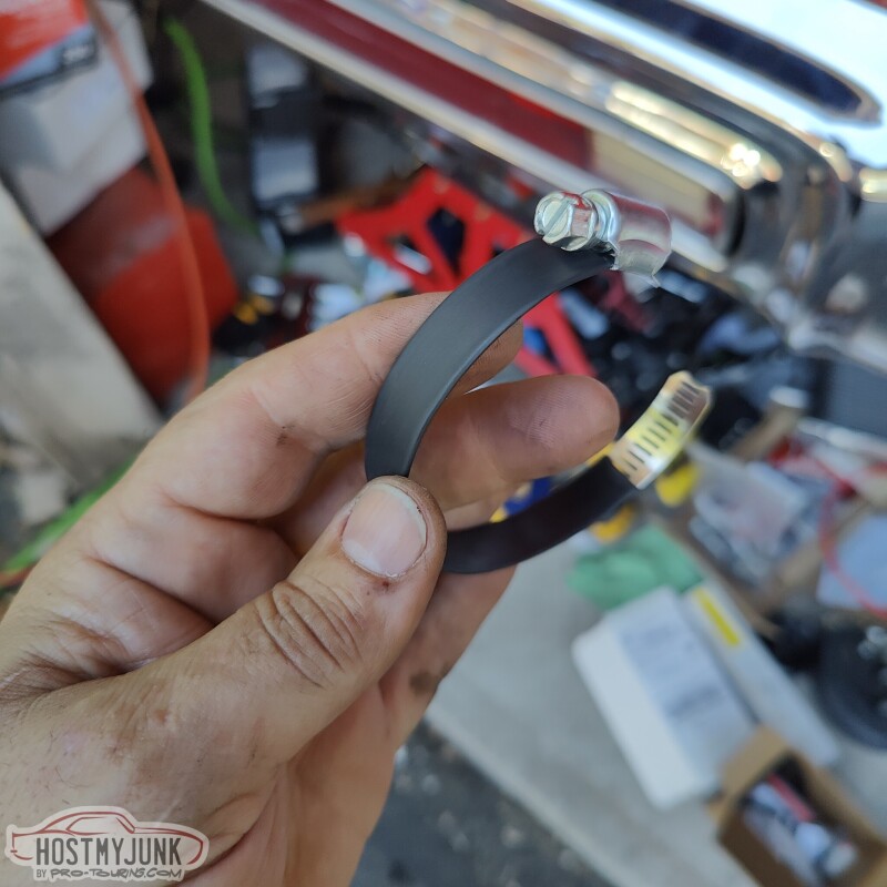
It is used to hold the two heater hoses and a couple of wire loom up and off the coils. You don't want anything rubbing against each other as the engine moves around.
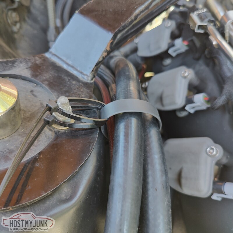
The zip ties are going to be replaced by a simple little bracket (to be shown later).
More to come...
Andrew
Here is the butt connector that I like to use. These are made by either 3M or Molex (I forget which) and they are available from Waytek Wire and I am sure many other vendors. I like using the non insulated butt connectors because they are the least bulky option. Also, when splicing multiple wires together in the same location, you want to stagger the butt splices to minimize the bulkiness in that one spot.
You want to strip the wire so a about half the width of the wire gauge is showing between the insulation and the butt connector. This is done for strain relief. Also notice the seam on the butt connector, this will be important when making the crimp.
I use Raychem SCL heat shrink tubing for these kinds of connections. The SCL is very rigid and it has potting compound inside that will melt and seal the connection. I cut the length of the SCL to be about twice the length of the splice.
Make sure to remember that the heat shrink needs to go on before the final crimp is made.
This is the crimper tool that I use for these butt connectors. Make sure the seam is supported by the die on the back side.
The crimper has a ratcheting mechanism that will not release until the crimper is squeezed a sufficient amount. It is important not to over-crimp as this will distort the butt connector.
Here you can see both sides have been crimped. Also note what I am using for the actual wire. Instead of running a single wire through an existing loom, I re-used the 7 strand shielded cable that used to be for my second DBW throttle body. Using the shielded cable is not necessary, but it is much easier to run a length of it rather than a single wire conductor. It also leaves other conductors for future use.
Here is the Raychem SCL after it was fully recovered. You can see the melted potting compound oozing out. This effectively seals that connection from any possible moisture.
Here is the finished loom. You can see that I added a purple and black wire to the harness. These are just spare wires for possible future use. Having 3 wires in a loom, instead of 1 makes it more durable.
I used TechFlex F6 woven split loom to cover the harness. (somehow I do not have a picture of the finished loom).
Here is another little trick that can turn a simple hose clamp into looking like a custom part. I took some heat shrink tubing and recovered it over this stainless hose clamp.
It is used to hold the two heater hoses and a couple of wire loom up and off the coils. You don't want anything rubbing against each other as the engine moves around.
The zip ties are going to be replaced by a simple little bracket (to be shown later).
More to come...
Andrew
The following 2 users liked this post by Project GatTagO:
kwhizz (09-27-2023), wretched73 (09-27-2023)

The following 3 users liked this post by Austin_Jim:
09-24-2023, 02:10 PM
#1292
09-24-2023, 03:18 PM
#1293
TECH Senior Member
Thread Starter
iTrader: (7)
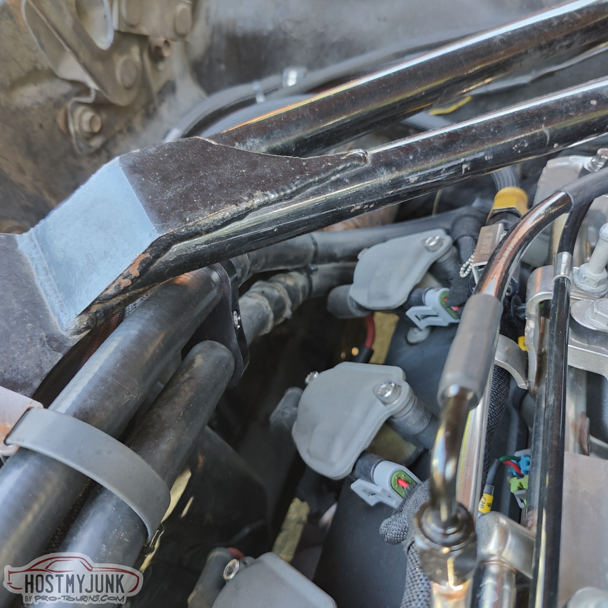
Here is the bracket that Vic made for the hose clamp. It is just a piece of .080" thick steel with a hole and a milled slot. Sorted...
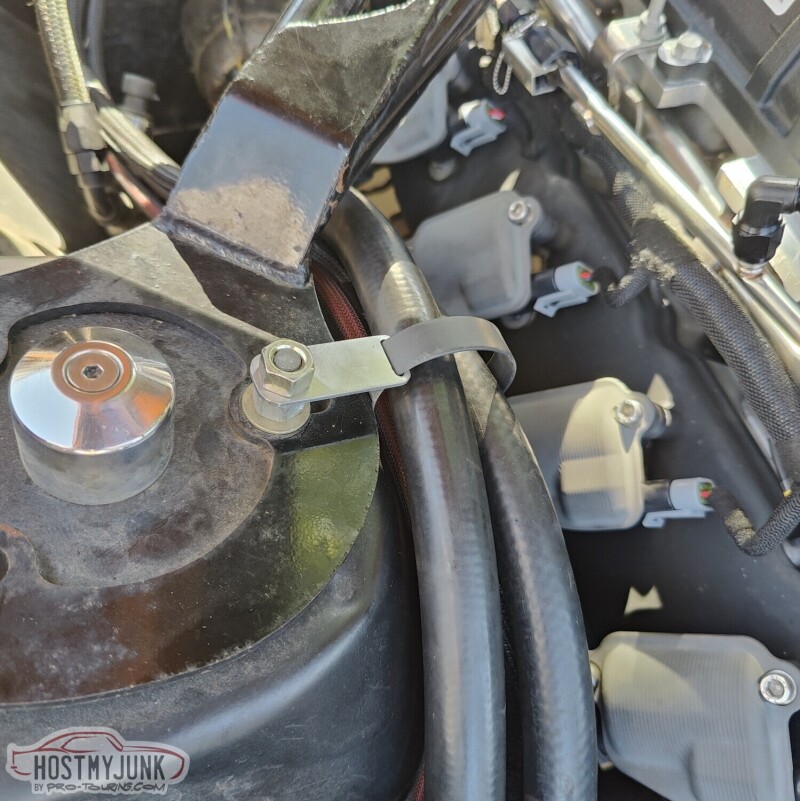
By this point the car was running and driving, but I did not have an air filter or a cold intake kit, so it was time to make one. I eyeballed where the hole needs to be and marked it.
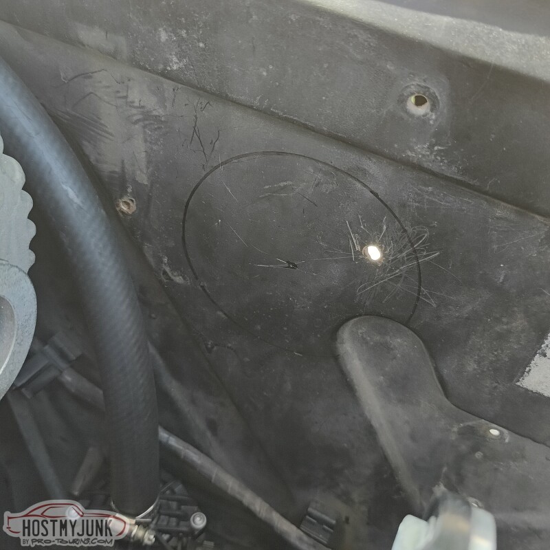
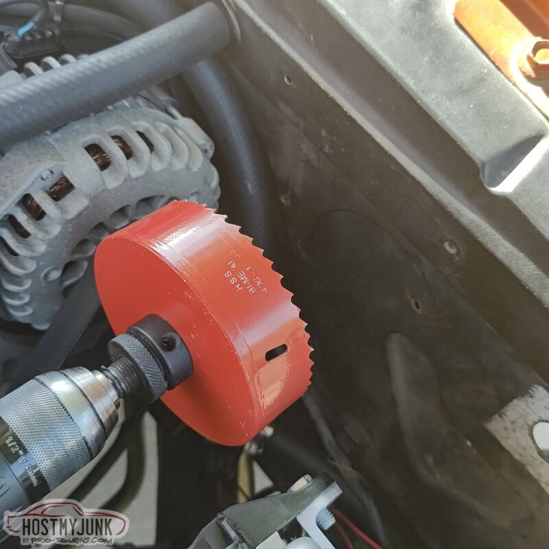
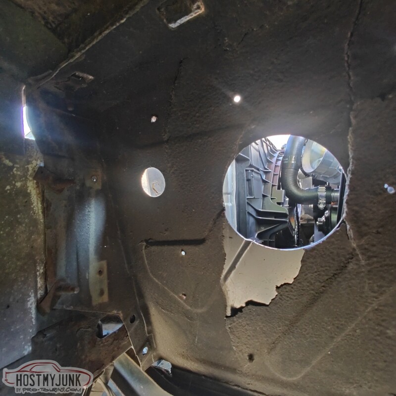
I drilled a small pilot hole, then used a 4 3/4" hole saw to make the hole. I believe I drilled from inside the wheel well into the engine compartment.
This is from the engine bay side...
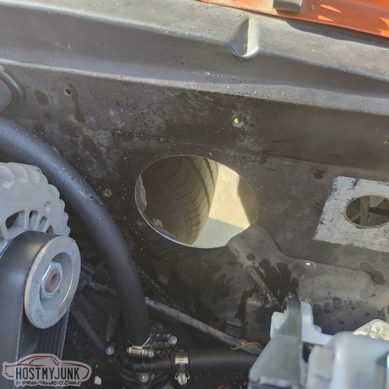
This is from the wheel well side...
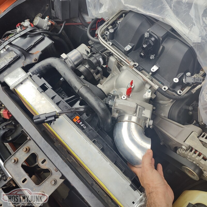
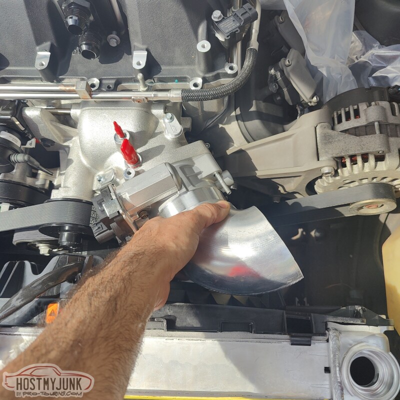
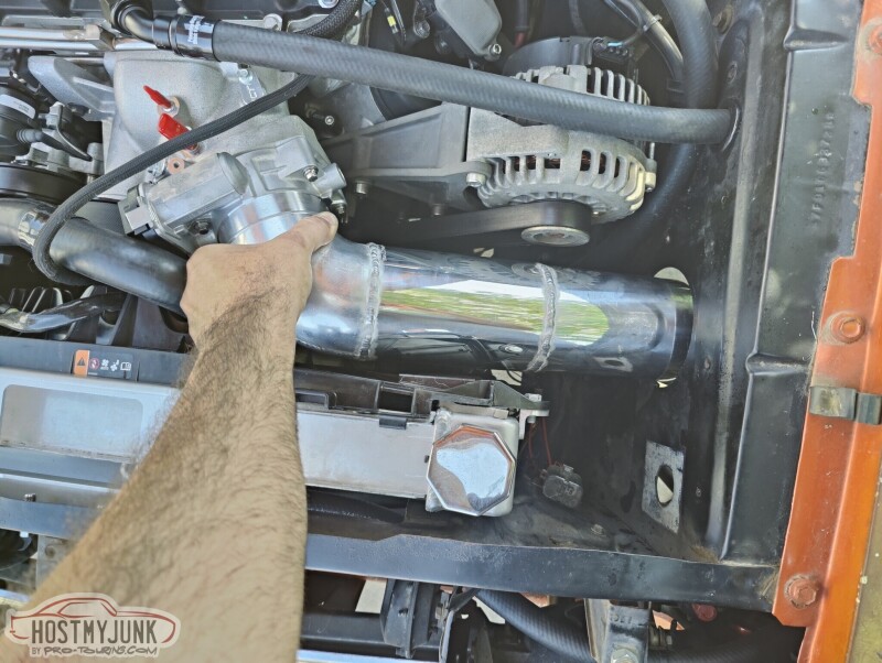
Vic miter cut the the elbow so that it would point towards the hole.
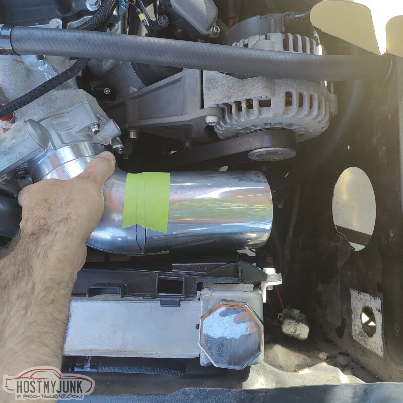
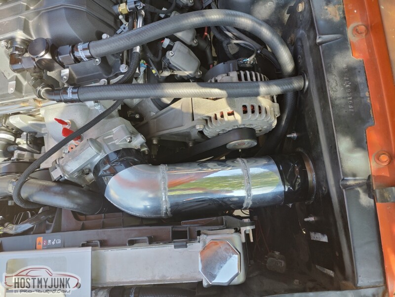
After mocking it up with the tube taped to the elbow, Vic welded some straight sections of 4" tubing, so it would reach the filter. It is actually a little long here but was later trimmed.
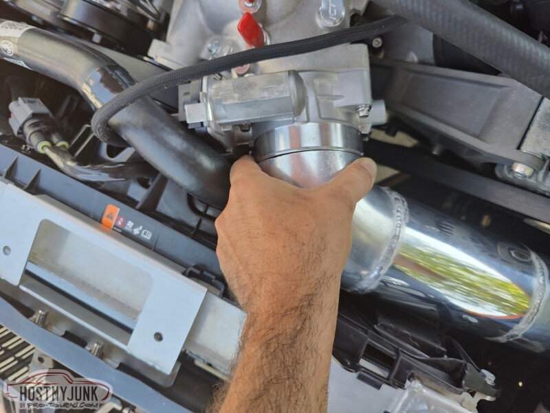
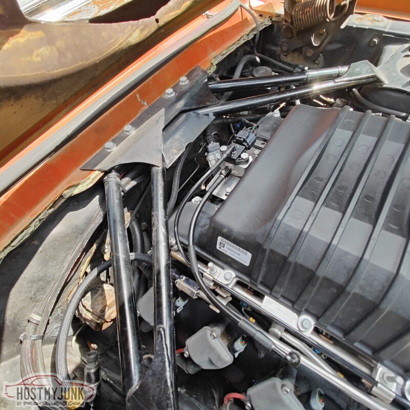
Pretty good fit against the throttle body.
This is the finished bulkhead panel for the filter. On the engine bay side, we used a 4" straight stainless pipe that was left over from the GTO exhaust system.
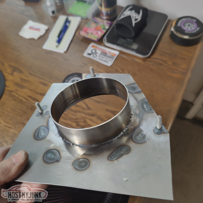
On the wheel well side, Vic rolled a 6" ring so that it would match the filter. This was actually the first filter that I got for the GTO. The GTO got a bigger filter and this one worked perfectly here.
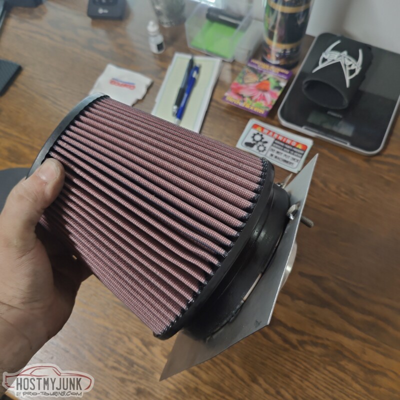
Here is everything installed temporarily with duct tape. I later got silicone sleeves.
This is how it looks from the wheel well.
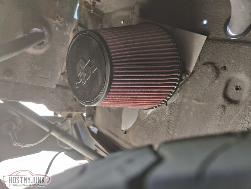
I later added a little K&N water "sock" in case I got caught in a big storm.
Andrew
By this point the car was running and driving, but I did not have an air filter or a cold intake kit, so it was time to make one. I eyeballed where the hole needs to be and marked it.
I drilled a small pilot hole, then used a 4 3/4" hole saw to make the hole. I believe I drilled from inside the wheel well into the engine compartment.
This is from the engine bay side...
This is from the wheel well side...
Vic miter cut the the elbow so that it would point towards the hole.
After mocking it up with the tube taped to the elbow, Vic welded some straight sections of 4" tubing, so it would reach the filter. It is actually a little long here but was later trimmed.
Pretty good fit against the throttle body.
This is the finished bulkhead panel for the filter. On the engine bay side, we used a 4" straight stainless pipe that was left over from the GTO exhaust system.
On the wheel well side, Vic rolled a 6" ring so that it would match the filter. This was actually the first filter that I got for the GTO. The GTO got a bigger filter and this one worked perfectly here.
Here is everything installed temporarily with duct tape. I later got silicone sleeves.
This is how it looks from the wheel well.
I later added a little K&N water "sock" in case I got caught in a big storm.
Andrew
09-24-2023, 03:34 PM
#1294
TECH Apprentice


Originally Posted by Project GatTagO
I am glad you are getting something out of my posts. It seems like I am posting into an Internet vacuum sometimes...LOL
Andrew
Andrew
The following 4 users liked this post by Novapat67:
09-24-2023, 08:35 PM
#1295
TECH Senior Member
Thread Starter
iTrader: (7)
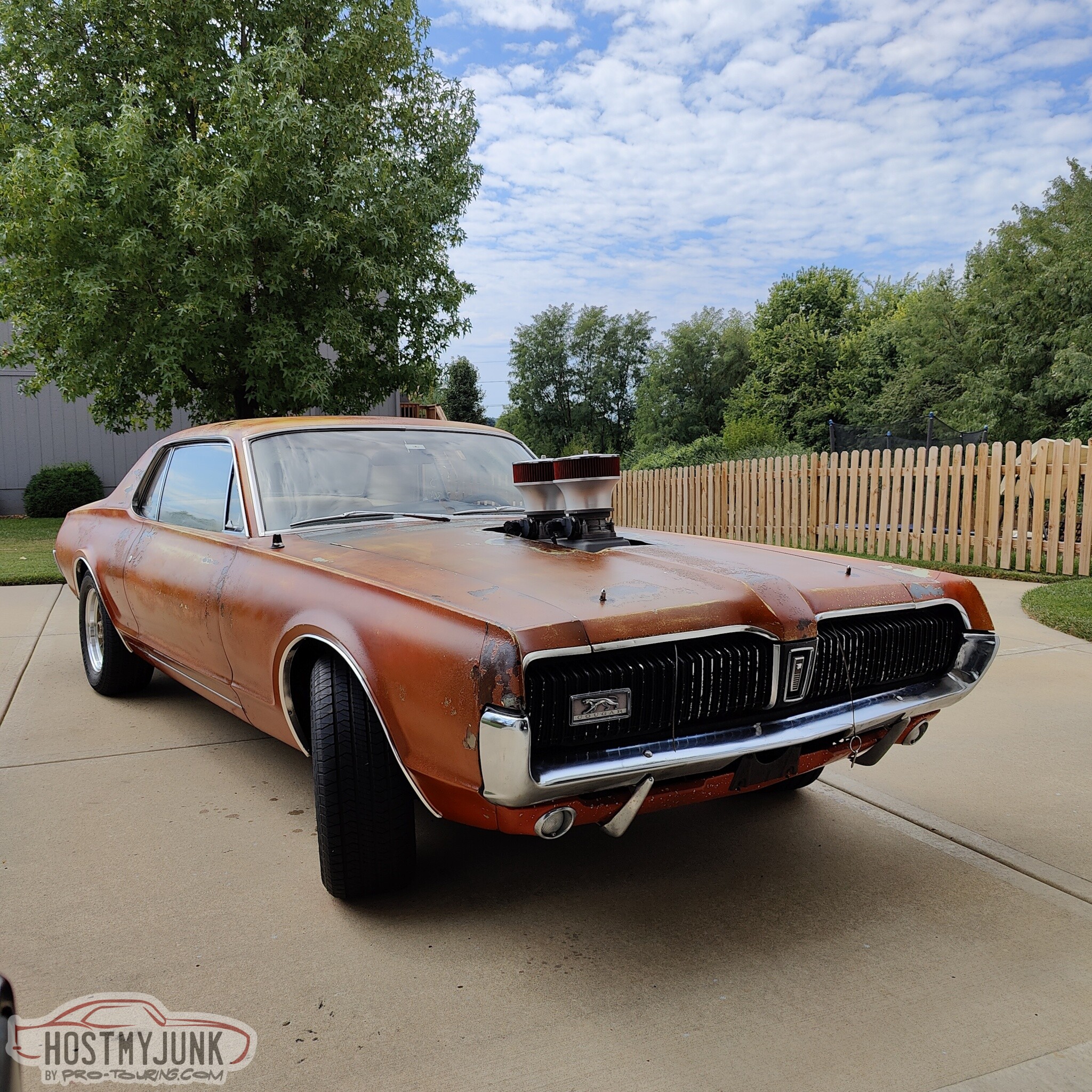
This car has gone from a of a "barn find", to a rolling chassis, to a 5.3L with a Holley HiRam intake with two DBW throttle bodies pocking through the hood. The 5.3L had a cam swap done, then it was replaced by a 6.2L engine with the same HiRam intake. That intake has now been replaced with a LSA supercharger.
This car has been awesome.
Andrew
09-25-2023, 09:39 AM
#1296
TECH Senior Member
Thread Starter
iTrader: (7)
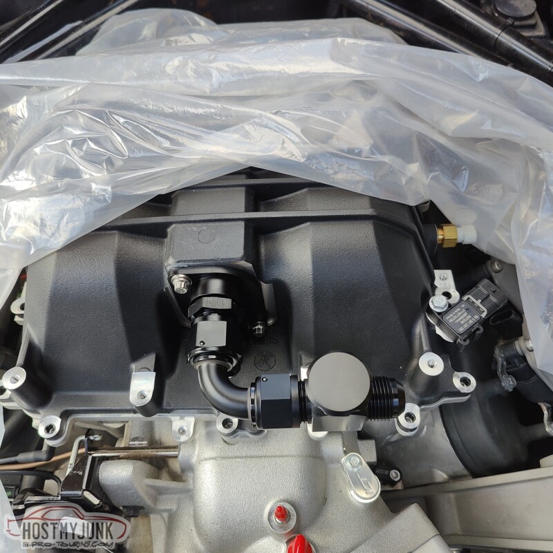
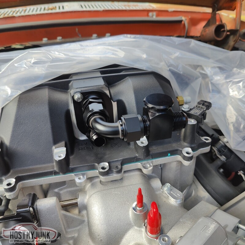
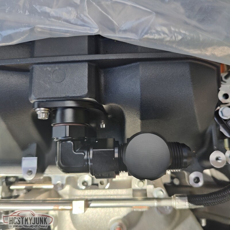
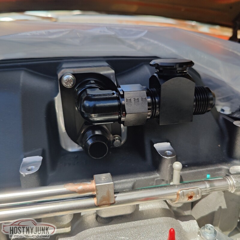
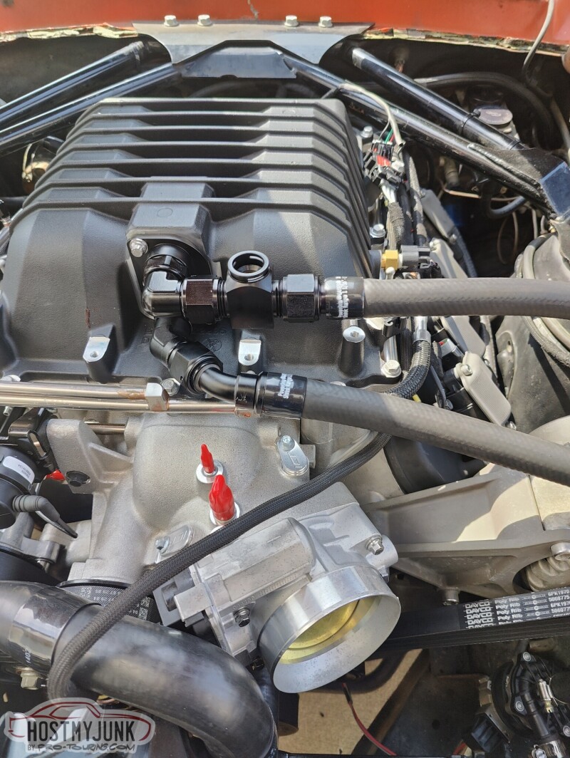
This is almost the final combination of fittings that I ended up using on the supercharger lid for the A2W intercooler plumbing. As you can see in a later picture, the top fitting was changed to a hard 90 ORB to AN fitting.
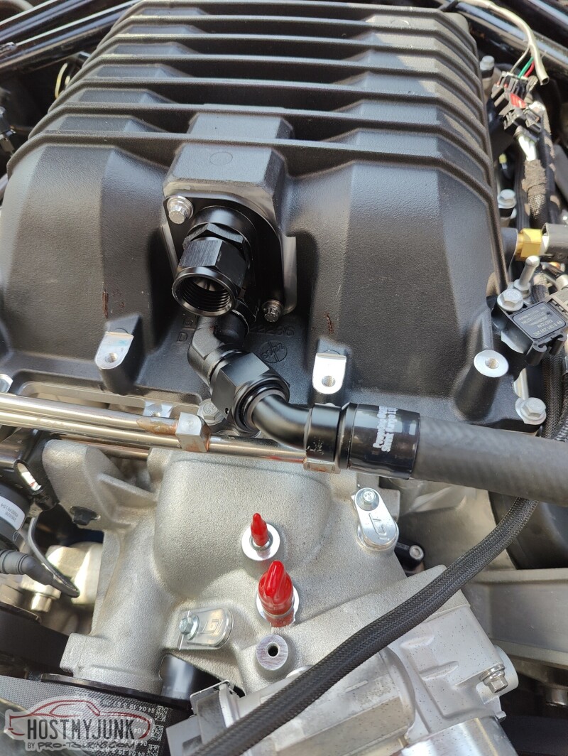
Here are the hoses with the Gates heat shrink clamps fully recovered.
This is the fill/bleed fitting from LSx Innovations. This is a very functional part, although I wish it looked a little less chunky. You can see the ORB to AN 90 degree adapter between the intercooler and the fill block.
I took some basic measurements off the fill block plug and my friend Blake drew up and 3D printed this little adapter. The part that slips into the fill fitting was a little undersized, so Vic made a little copper sleeve so that the fitting seals well against the o-ring that is inside the fill block.
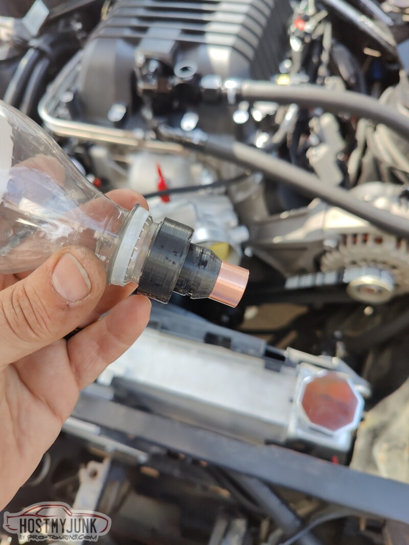
The 3D printed part was designed to accept a standard soft drink bottle. This worked pretty well, although it did leak a little. I added some Teflon tape to the threads and used some tape around the bottle and fitting, and that kept the leaking to small drips. To fill the system we added water and ran the pump. The the pump circulated the water, bubbles would work their way out of the system. It did not take long to fully fill and burp the system.
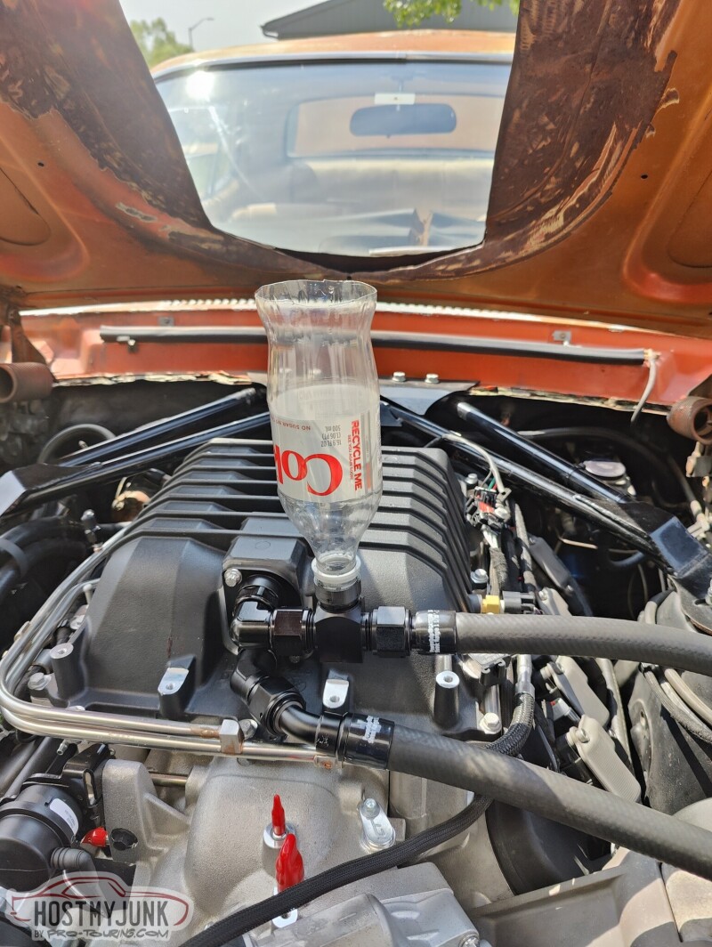
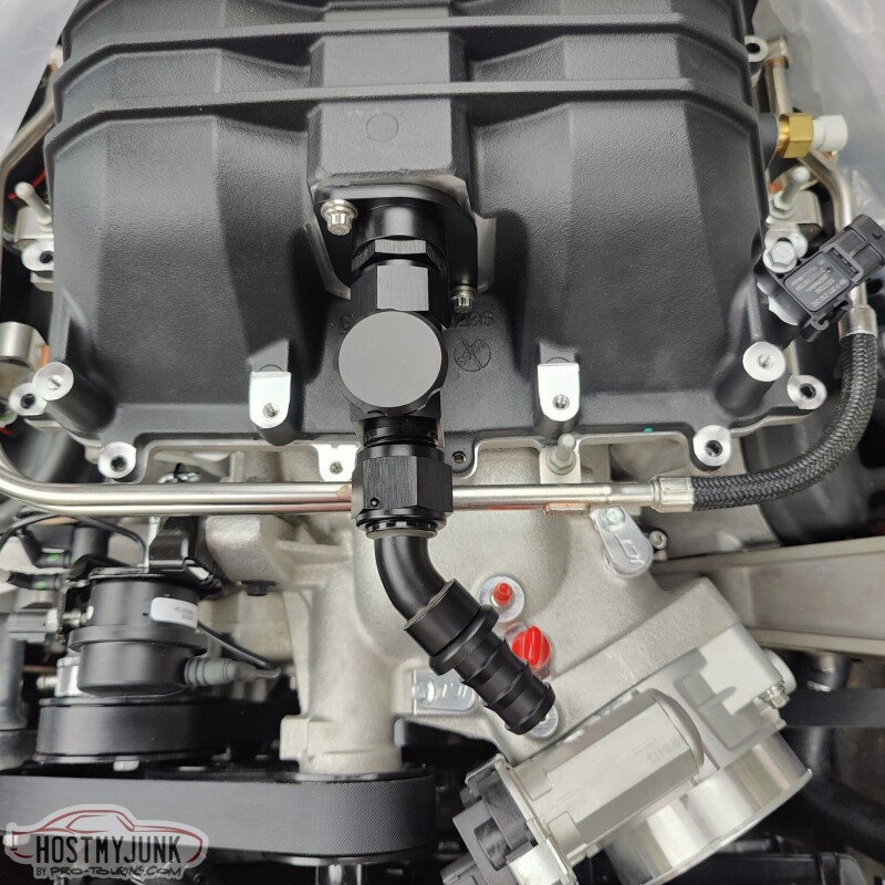
Th LSA blower has a computer controlled by-pass valve. This is a critical component of modern superchargers, as it greatly reduces the pumping forces of the supercharger at idle and low throttle situations. However, under full load, vacuum is removed from the by-pass diaphragm, the valve shuts, and full boost is available. I removed the computer controlled solenoid and used the vacuum port hooked to the by-pass valve actuator. This left the upper port on the supercharger case. This port sees both vacuum and boost, so it was the perfect spot to use with my "electronic" fuel pressure regulator.
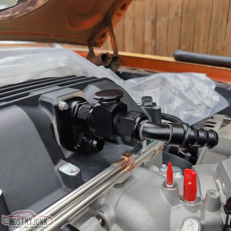
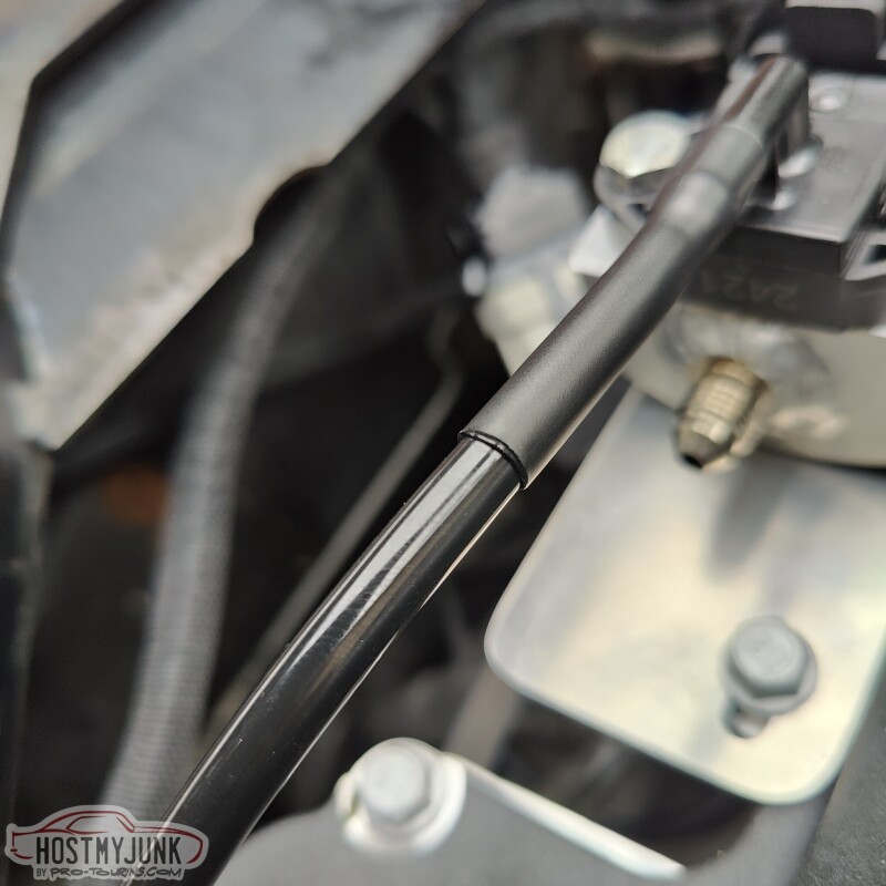
I used a little rubber 90 degree fitting that connected to a small 90 degree plastic elbow, that connected to a length of nylon tubing. The nylon tube was heated with a heat gun and once it is slipped over the plastic fitting, it makes a tight seal.
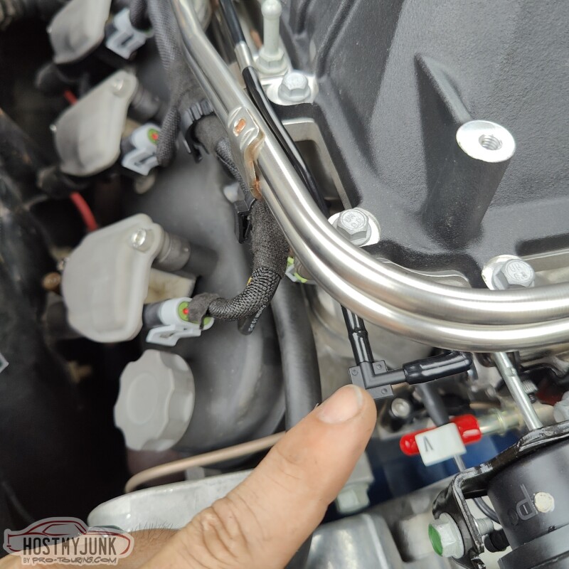
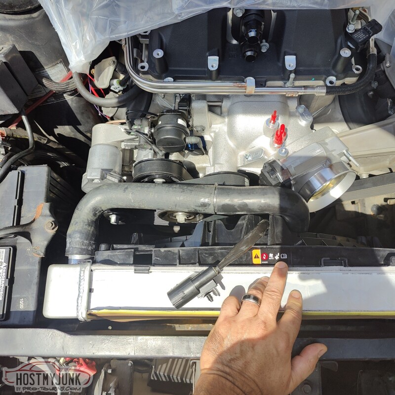
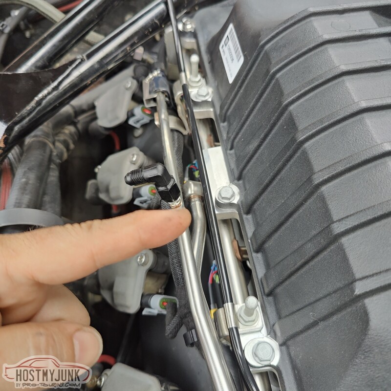
The nylon tubing runs along the stock fuel rails and is held in place with small, stainless P-clamps. You can also see the Schrader valve on the stock rail. This will also be used. If you look closely, you can also see that the fuel rail inlet has been lowered to clear the strut tower brace.
Both the vacuum/boost tubing and the fuel supply go to this Bosch differential fuel pressure sensor. The Bosch part number for the sensor is: 0 261 230 093. It was used on many Ford (and many other manufacturers) vehicles, from about the mid 2000s.
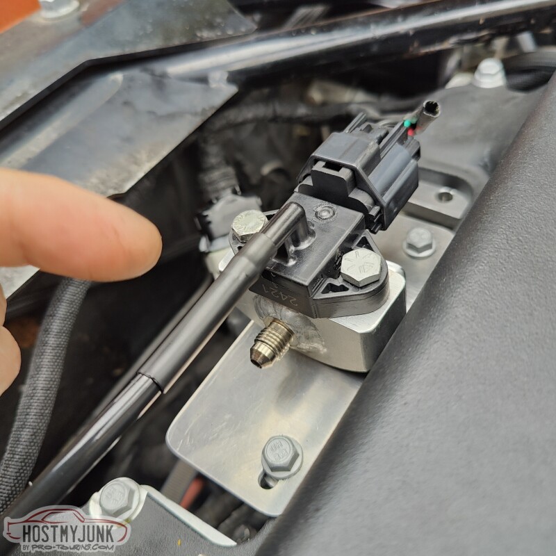
The plastic nipple was a little big for the nylon hose so I use a generous length of Raychem SCL to mate the sensor with the nylon tubing. Here, again, you can see the glue inside the SCL melting and forming a solid seal.
The hose that originally connected the fuel supply line to the rail wasn't quite right for this fuel rail, so I made a new hose using Earl's Ultrapro hose and twist on hose ends. I added a little bling by adding some gold accents to the fittings.
The last piece of the puzzle was the hose that connects the Schrader valve to the sensor. I use a premade brake hose that was 13" long with a straight fitting on one side and a 90 degree fitting on the other. Both fittings are AN -4.
Andrew
Here are the hoses with the Gates heat shrink clamps fully recovered.
This is the fill/bleed fitting from LSx Innovations. This is a very functional part, although I wish it looked a little less chunky. You can see the ORB to AN 90 degree adapter between the intercooler and the fill block.
I took some basic measurements off the fill block plug and my friend Blake drew up and 3D printed this little adapter. The part that slips into the fill fitting was a little undersized, so Vic made a little copper sleeve so that the fitting seals well against the o-ring that is inside the fill block.
The 3D printed part was designed to accept a standard soft drink bottle. This worked pretty well, although it did leak a little. I added some Teflon tape to the threads and used some tape around the bottle and fitting, and that kept the leaking to small drips. To fill the system we added water and ran the pump. The the pump circulated the water, bubbles would work their way out of the system. It did not take long to fully fill and burp the system.
Th LSA blower has a computer controlled by-pass valve. This is a critical component of modern superchargers, as it greatly reduces the pumping forces of the supercharger at idle and low throttle situations. However, under full load, vacuum is removed from the by-pass diaphragm, the valve shuts, and full boost is available. I removed the computer controlled solenoid and used the vacuum port hooked to the by-pass valve actuator. This left the upper port on the supercharger case. This port sees both vacuum and boost, so it was the perfect spot to use with my "electronic" fuel pressure regulator.
I used a little rubber 90 degree fitting that connected to a small 90 degree plastic elbow, that connected to a length of nylon tubing. The nylon tube was heated with a heat gun and once it is slipped over the plastic fitting, it makes a tight seal.
The nylon tubing runs along the stock fuel rails and is held in place with small, stainless P-clamps. You can also see the Schrader valve on the stock rail. This will also be used. If you look closely, you can also see that the fuel rail inlet has been lowered to clear the strut tower brace.
Both the vacuum/boost tubing and the fuel supply go to this Bosch differential fuel pressure sensor. The Bosch part number for the sensor is: 0 261 230 093. It was used on many Ford (and many other manufacturers) vehicles, from about the mid 2000s.
The plastic nipple was a little big for the nylon hose so I use a generous length of Raychem SCL to mate the sensor with the nylon tubing. Here, again, you can see the glue inside the SCL melting and forming a solid seal.
The hose that originally connected the fuel supply line to the rail wasn't quite right for this fuel rail, so I made a new hose using Earl's Ultrapro hose and twist on hose ends. I added a little bling by adding some gold accents to the fittings.
The last piece of the puzzle was the hose that connects the Schrader valve to the sensor. I use a premade brake hose that was 13" long with a straight fitting on one side and a 90 degree fitting on the other. Both fittings are AN -4.
Andrew
The following 2 users liked this post by Project GatTagO:
jrs396 (09-25-2023), ryeguy2006a (09-25-2023)


The following users liked this post:
Project GatTagO (09-25-2023)
09-25-2023, 10:34 PM
#1298
TECH Senior Member
Thread Starter
iTrader: (7)
With everything under the hood being pretty well sorted out, it was time to tackle the ugly hole in the hood. I looked all over the internet for ideas. I wanted to keep it simple and subtle. I came across this early Mustang GT 350 scoop from Scott Drake:
Scott Drake GT 350 style scoop.
I ordered mine from Summit Racing. They had it in stock and it was at my door in two days. Sadly, I knew things were not going to go well when I saw the boot print on the side of the box, before I even opened it.
I opened the box and of course there is a dent in the side of the scoop where the boot print was.
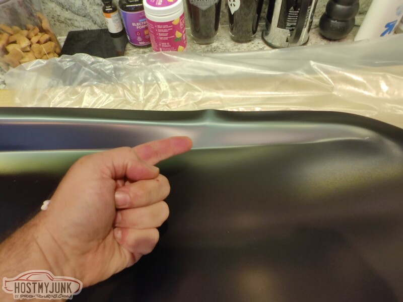
Looking at it on the hood, you can see that it is just not workable, not when I paid for a good part.
I made a call to Summit and a very empathetic customer service rep answered my call. She explained to me that unfortunately this happens a lot with this particular part. Summit should really double box it, but that's not really my concern. She assured me that a new scoop was forthcoming, and true to her word, a new scoop arrived two days later. She also told me that UPS might be sending a tag to pick up the box. I held on to it for 30 days and then I posted it on one of the vintage mustang forums. I couldn't bear throw it away, so I gave it away for the price of shipping. Within a few hours I had a taker and it went off to California.
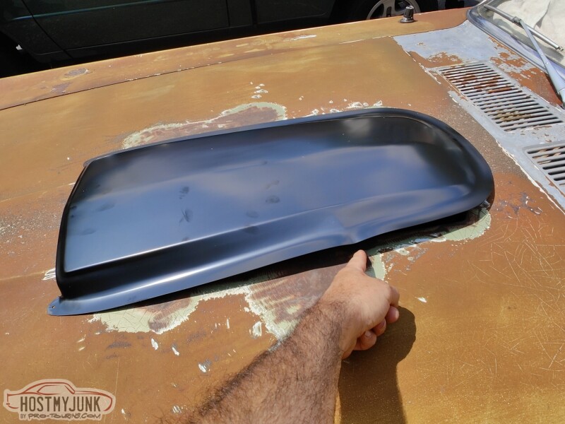
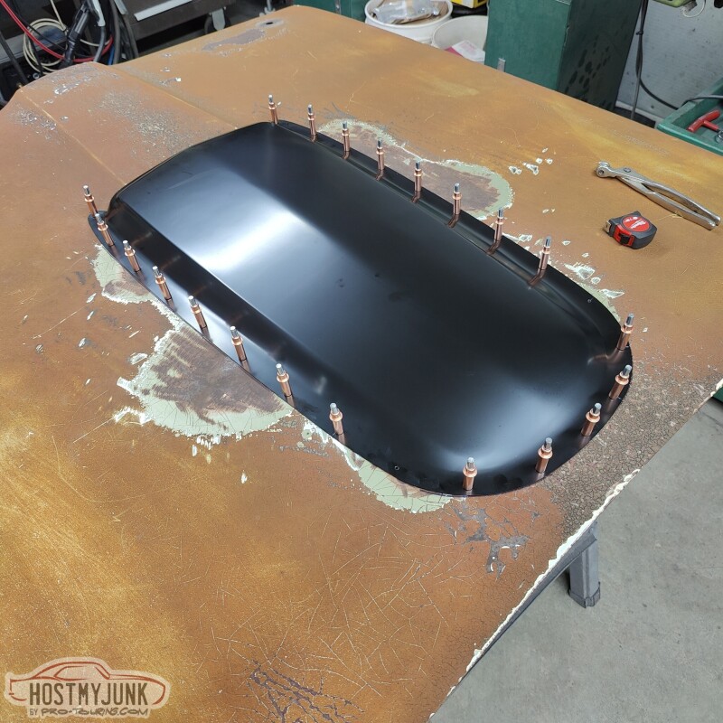
This is the replacement scoop and you can see how nicely it follows the contours of the hood.
Then it was off to Vic's to get the scoop attached to the hood. We took off the hood so that we could work on it inside the air conditioned garage. We were doing this when we had that 2-3 week long heat wave in the midwest. Day time temperatures were over 100F degrees, which made working outside pretty brutal.
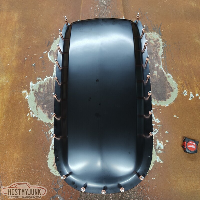
We measured out the length and figured out what looked to be visually appealing spacing for the rivets. Vic marked the hole locations and use a punch to make the hole. The punch ensured even spacing from the edge of the scoop and left perfect 1/8" diameter holes.
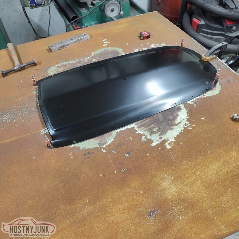
Once the holes were punched in the scoop it was centered on the hood and over the hole and the two front holes were drilled. Cleco fasteners were used to temporarily hold the scoop in place as more holes were drilled around the circumference of the scoop.
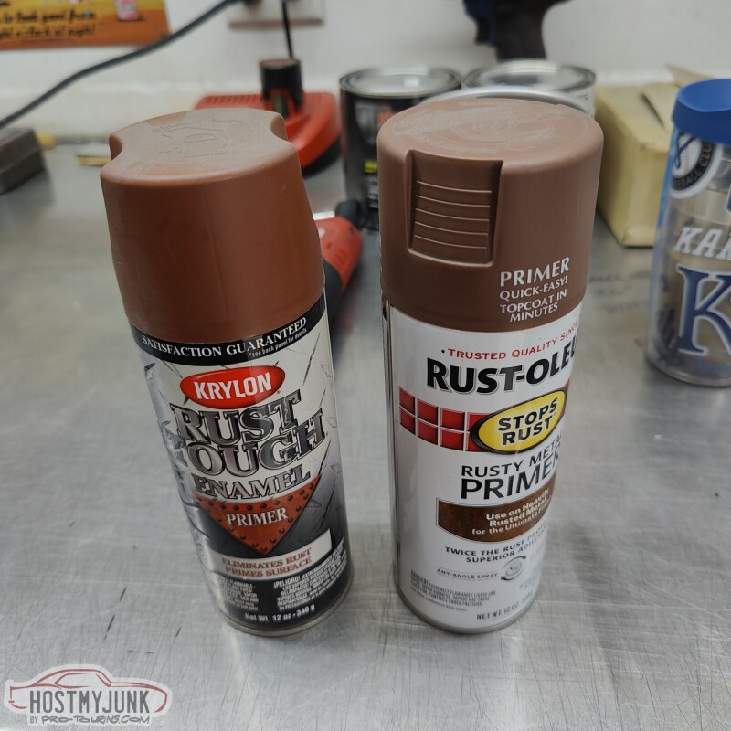
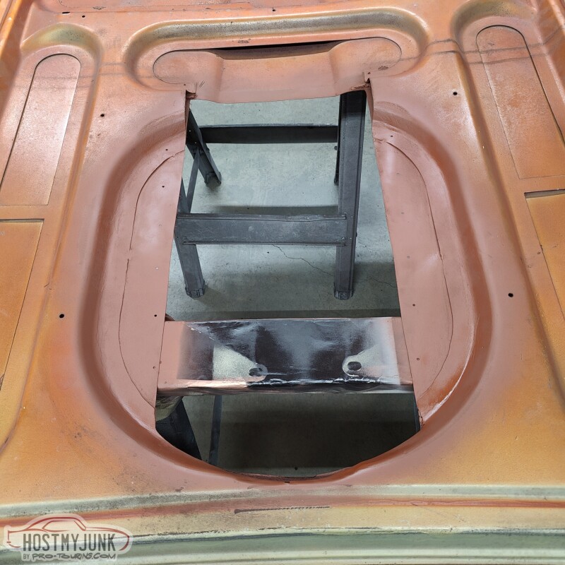
After the holes were drilled, but before riveting the scoop to the hood, I wanted to clean up the grinding marks on the underside of the hood. I wiped everything down with acetone and used one of these primers to mist the dish shaped area that is under the scoop.
Turned out pretty good. Certainly better then it was.
Here is the finally riveted scoop on the hood.
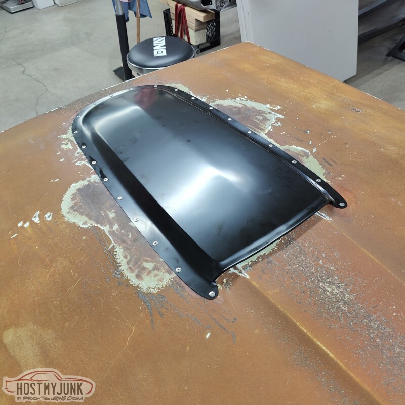
Vic had a chose of rivet style. I chose the large head rivets because they made them look purposeful. Like we meant to rivet the scoop and we are proud of it.
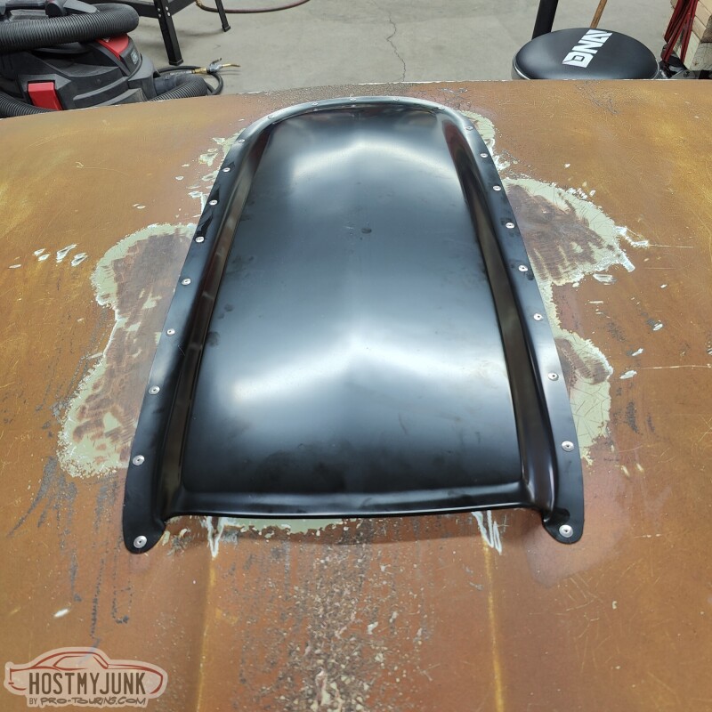
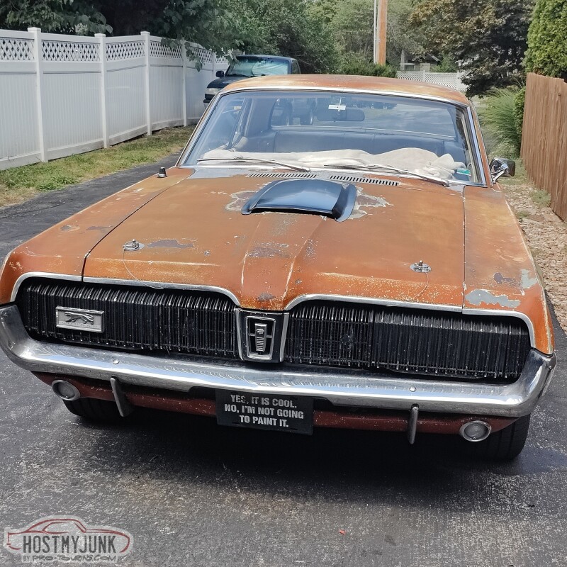
Here she is with her new, holeless, and scooped hood. I think it looks fantastic. The nose suddenly got a lot longer and the whole car became sleeker. Dare I say that it even looks dapper!
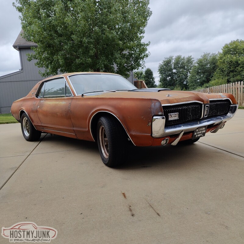
Here she is, almost to the day, from a year ago.
Post up your thoughts on the new look!
Andrew
Scott Drake GT 350 style scoop.
I ordered mine from Summit Racing. They had it in stock and it was at my door in two days. Sadly, I knew things were not going to go well when I saw the boot print on the side of the box, before I even opened it.
I opened the box and of course there is a dent in the side of the scoop where the boot print was.
Looking at it on the hood, you can see that it is just not workable, not when I paid for a good part.
I made a call to Summit and a very empathetic customer service rep answered my call. She explained to me that unfortunately this happens a lot with this particular part. Summit should really double box it, but that's not really my concern. She assured me that a new scoop was forthcoming, and true to her word, a new scoop arrived two days later. She also told me that UPS might be sending a tag to pick up the box. I held on to it for 30 days and then I posted it on one of the vintage mustang forums. I couldn't bear throw it away, so I gave it away for the price of shipping. Within a few hours I had a taker and it went off to California.
This is the replacement scoop and you can see how nicely it follows the contours of the hood.
Then it was off to Vic's to get the scoop attached to the hood. We took off the hood so that we could work on it inside the air conditioned garage. We were doing this when we had that 2-3 week long heat wave in the midwest. Day time temperatures were over 100F degrees, which made working outside pretty brutal.
We measured out the length and figured out what looked to be visually appealing spacing for the rivets. Vic marked the hole locations and use a punch to make the hole. The punch ensured even spacing from the edge of the scoop and left perfect 1/8" diameter holes.
Once the holes were punched in the scoop it was centered on the hood and over the hole and the two front holes were drilled. Cleco fasteners were used to temporarily hold the scoop in place as more holes were drilled around the circumference of the scoop.
After the holes were drilled, but before riveting the scoop to the hood, I wanted to clean up the grinding marks on the underside of the hood. I wiped everything down with acetone and used one of these primers to mist the dish shaped area that is under the scoop.
Turned out pretty good. Certainly better then it was.
Here is the finally riveted scoop on the hood.
Vic had a chose of rivet style. I chose the large head rivets because they made them look purposeful. Like we meant to rivet the scoop and we are proud of it.
Here she is with her new, holeless, and scooped hood. I think it looks fantastic. The nose suddenly got a lot longer and the whole car became sleeker. Dare I say that it even looks dapper!
Here she is, almost to the day, from a year ago.
Post up your thoughts on the new look!
Andrew

The following 2 users liked this post by jrs396:
kwhizz (09-27-2023), Project GatTagO (09-26-2023)
09-30-2023, 10:40 PM
#1300
TECH Senior Member
Thread Starter
iTrader: (7)
It looks like I am about done, but there was actually quite a bit of work that still needed to be done in order to be ready for LS Fest East 2023.
There was always a fairly large opening between the grill and the core support, but with the removal of the hood latch, now that opening got a lot bigger. There was also a little loss of structural rigidity to the grills, because they tied into the hood latch, which in turn was bolted to the core support. I also didn't like the huge opening because I felt like air could go up and over the core support, instead of being forced through the heat exchanger and radiator.
This was the solution. Vic took some measurements, made a couple of templates, got a piece of aluminum from his pile and magic happened...This is the first fitment of the new close-out panel.
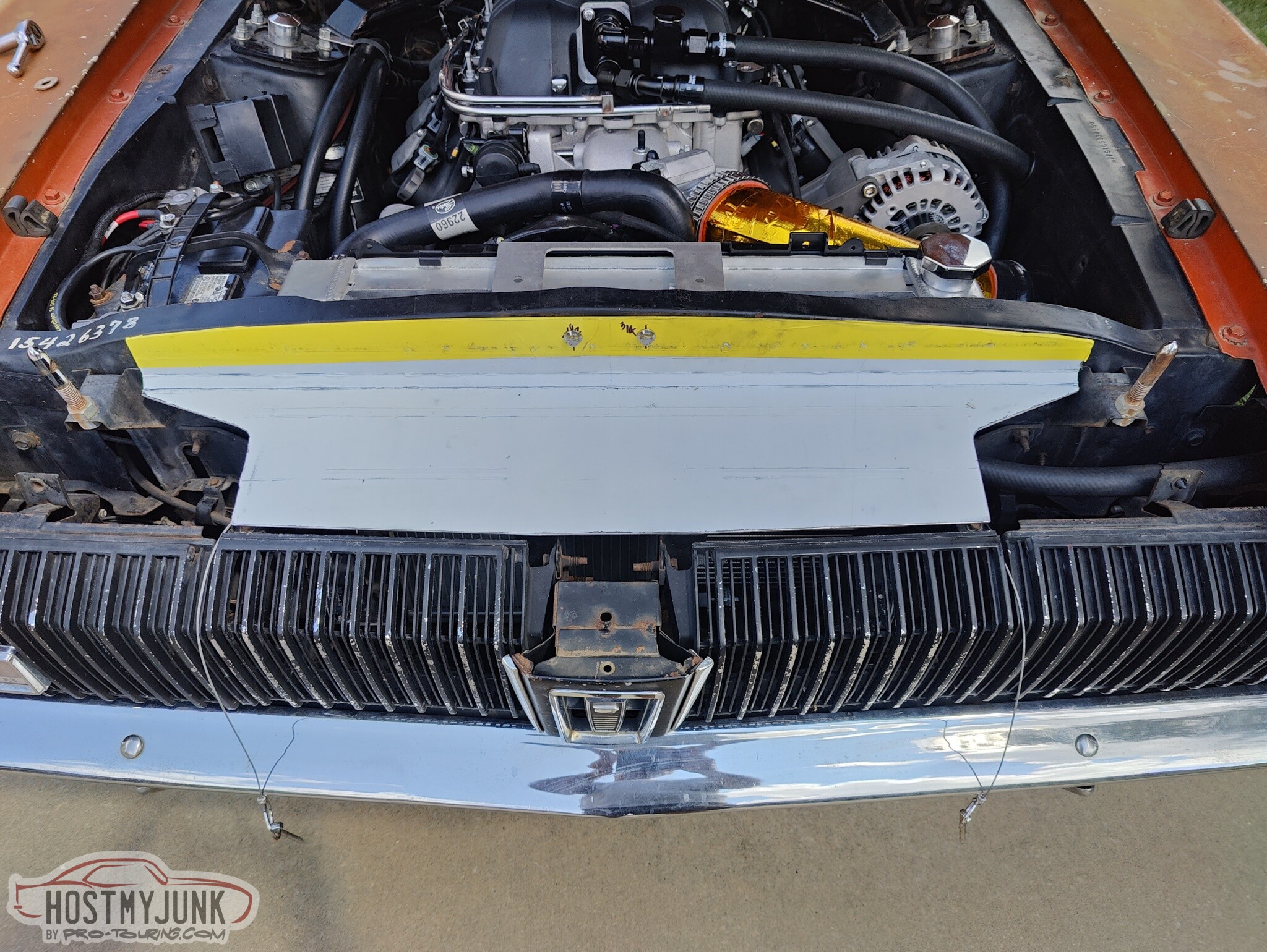
The panel attaches using two existing holes in the core support and two holes in the grill area. We also added rivnuts to the core support at the outer edges of the panel to tie it all together better.
If you are really paying attention then you may have also noticed a new alternator.
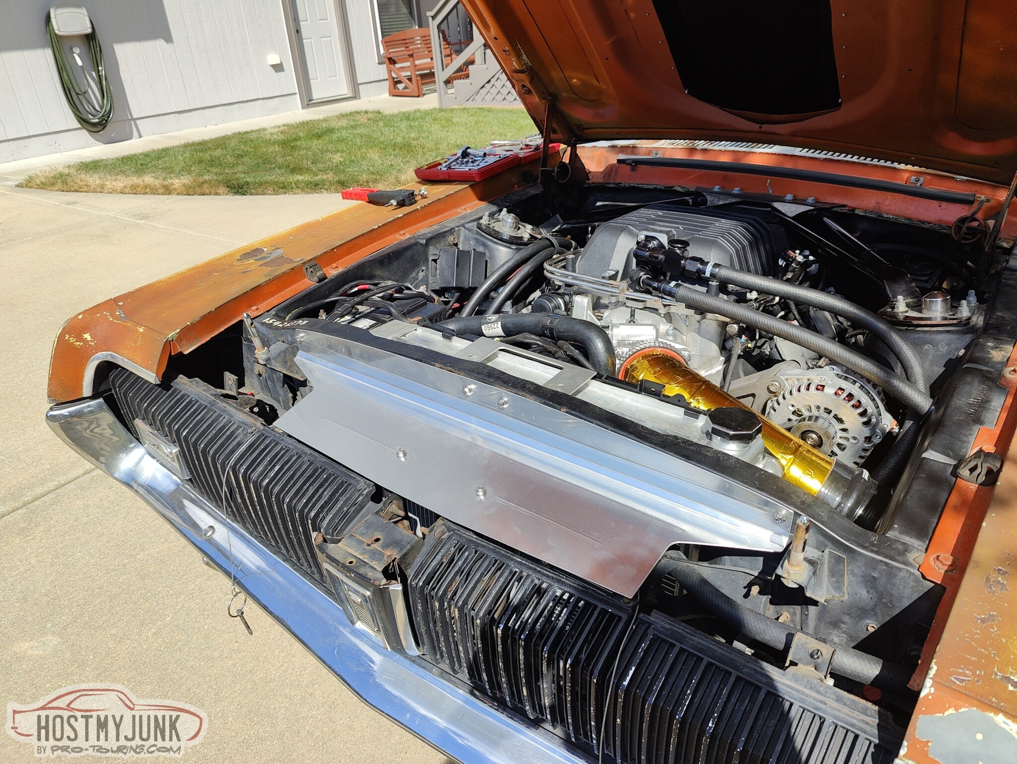
I also added some beauty clamps to the heater hoses.
These aren't necessary, but I think they add a nice touch.
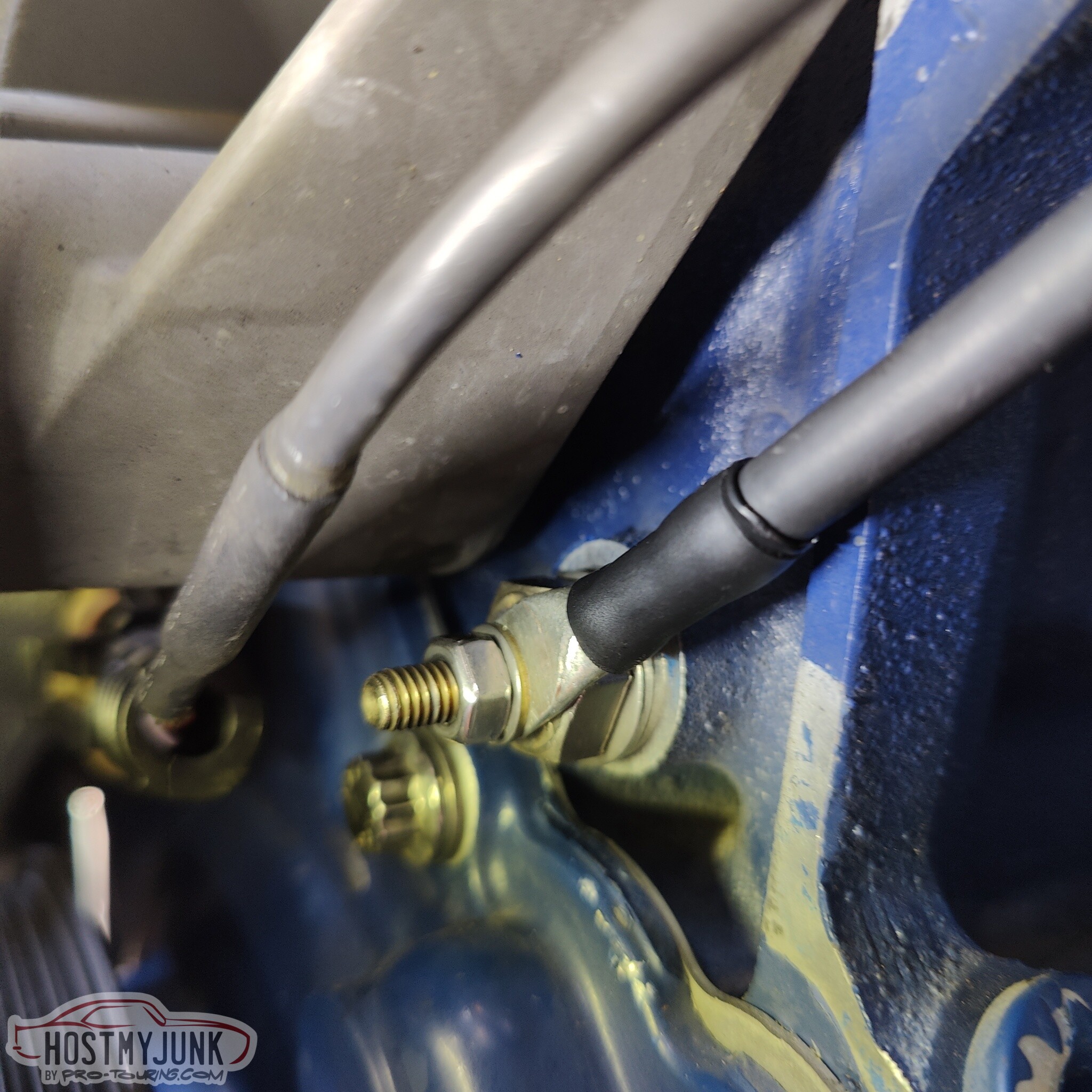
This is a ground strap for the new alternator. This is something that Powermaster recommends doing with their alternators. I used an existing 10mm hole in the block to hold the "bolt studs" that I made for this car back when I first built it. It is a cheap 10mm bolt that I drilled a hole in the head and welded a 6mm bolt to, hence, bolt studs. You can also see the potting compound of the SCL heat shrink. It actually is complete unnecessary here, but it gives it a finished look.
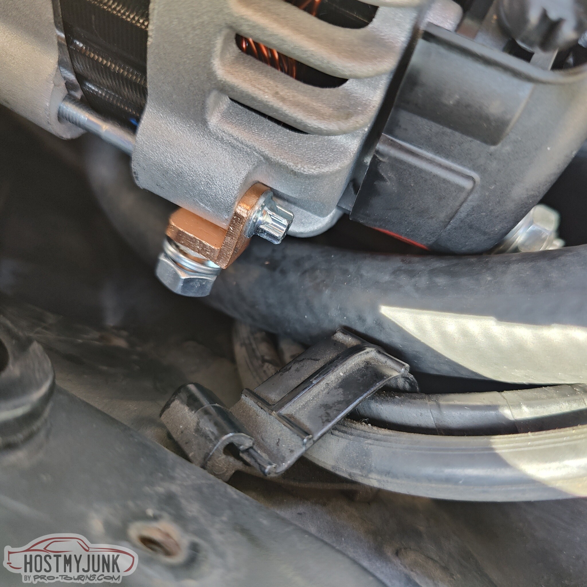
This is the case ground lug that was already installed on the new alternator. The reason for the new alternator is that the old one could not keep up with the new fan at idle. When the fan was at full speed (which actually almost never happens) the voltage output of the alternator would drop below 13 volts, and that's not acceptable for good battery life. This new alternator also happens to have a smaller than stock pulley, which isn't going to work...
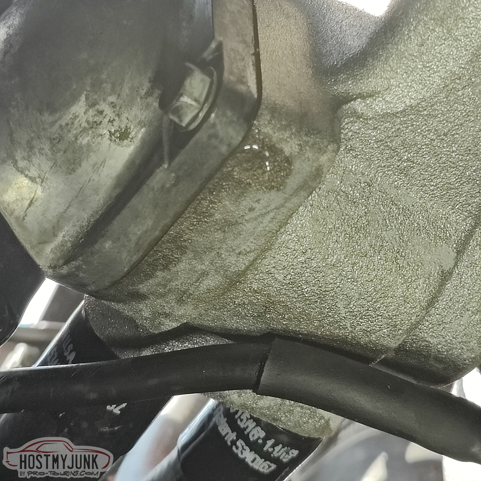
I also have a "one drop per hour" leak...
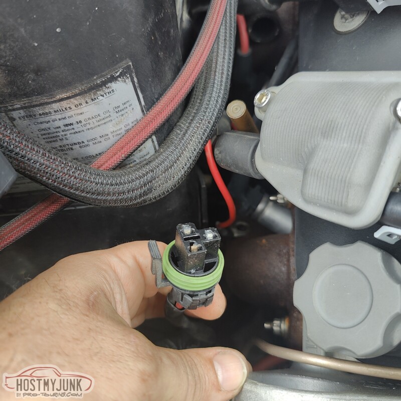
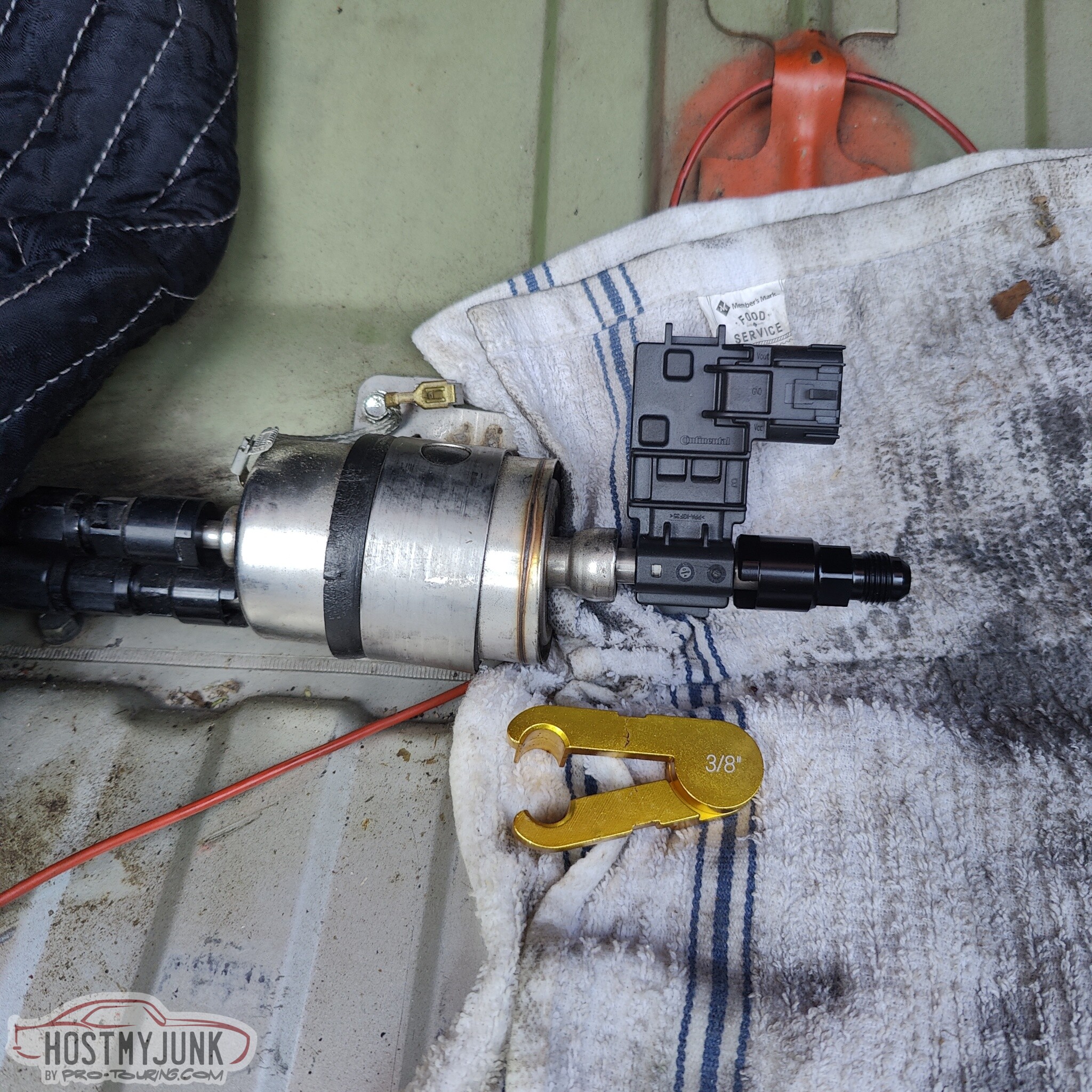
On to more fun stuff. I saw no reason why I should not make this fuel system be ethanol capable. The first thing that is needed is a flex fuel sensor. This is the exact same sensor that I got for the GTO. It is the same AC Delco branded Continental sensor that everyone seems to use.
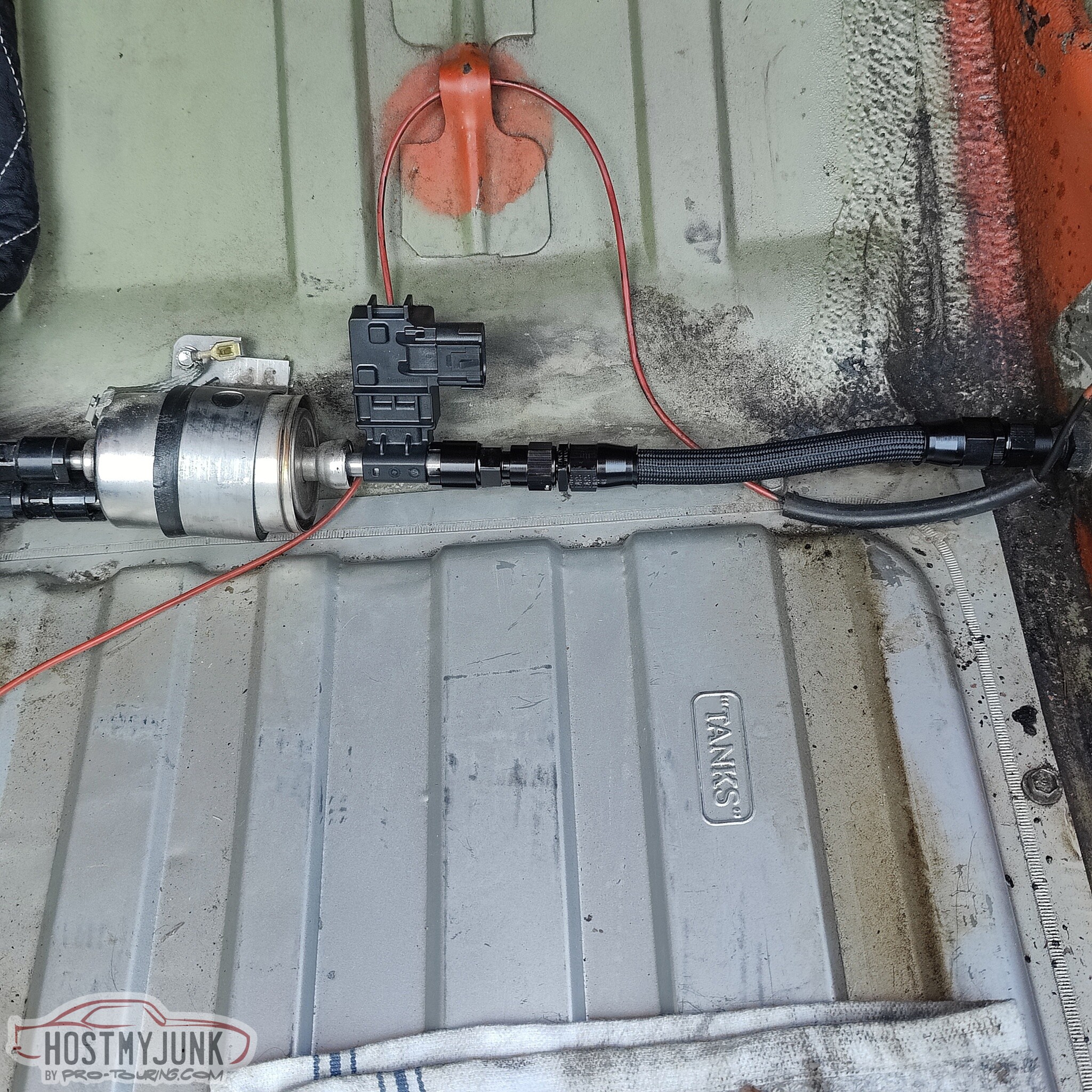
I thought about using a fancy sensor holder with a bypass passage, but after talking with Carl from VaperWorks, I was convinced that it was not needed. This is the easiest spot to mount the sensor. It is inside the trunk, and to the right is a bulkhead fitting and to the left is a Wix C5 Corvette filter/regulator.
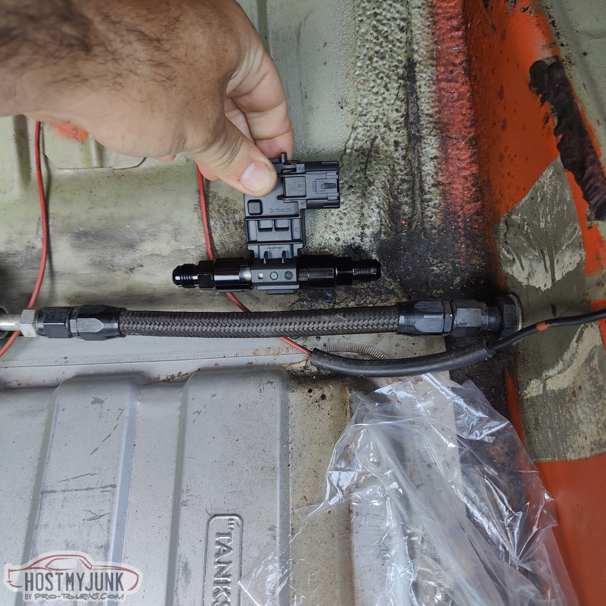
There was no sense in stacking adapters and unions. I could simply plug the sensor into the outlet of the Wix fuel filter. Doesn't get much easier then that!
I needed to make a new hose to go from the flexfuel sensor to the bulkhead. Here I am mocking it up to determine the exact length.
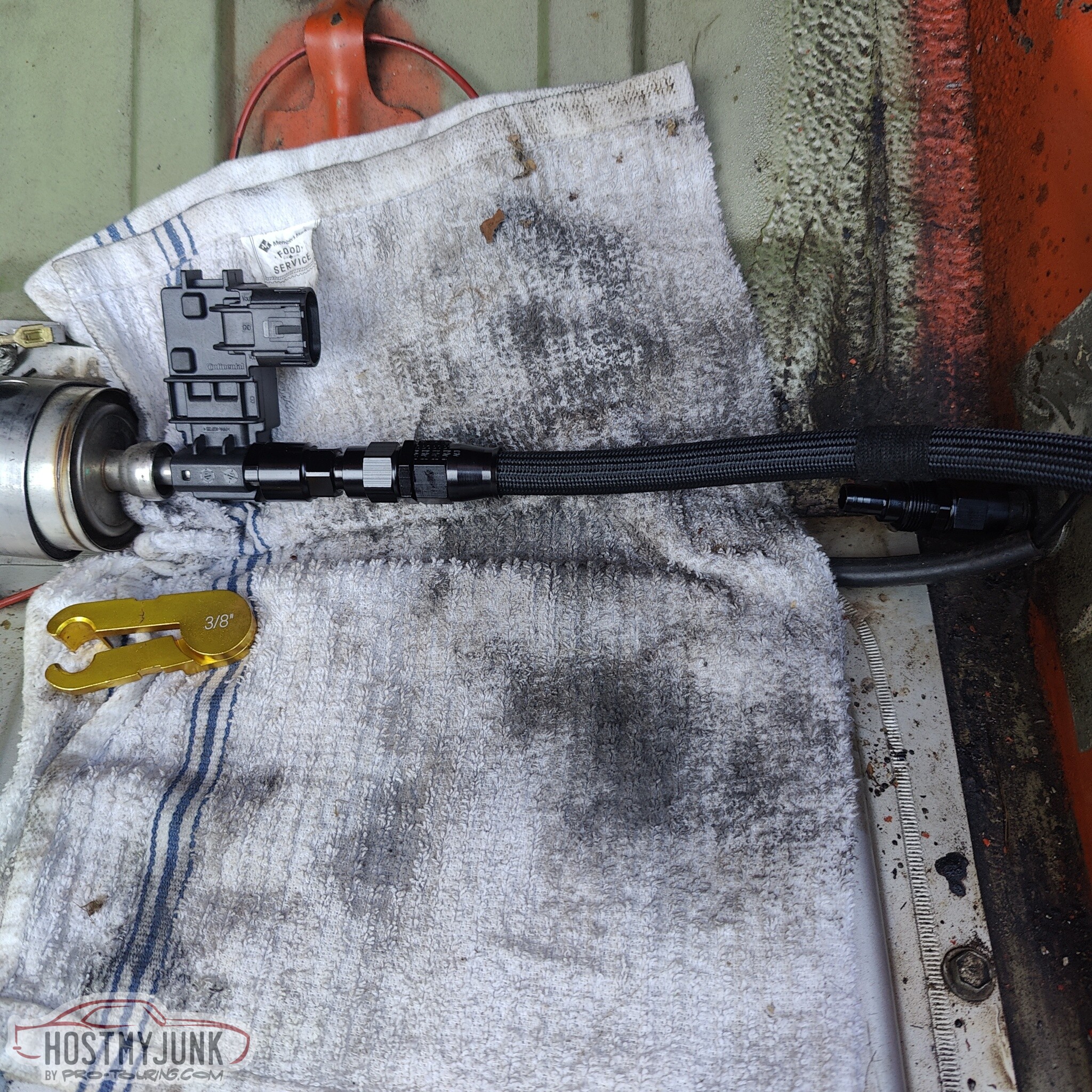
Sorted....
This sensor is of course useless until it is wired to the ECU...
Andrew
There was always a fairly large opening between the grill and the core support, but with the removal of the hood latch, now that opening got a lot bigger. There was also a little loss of structural rigidity to the grills, because they tied into the hood latch, which in turn was bolted to the core support. I also didn't like the huge opening because I felt like air could go up and over the core support, instead of being forced through the heat exchanger and radiator.
This was the solution. Vic took some measurements, made a couple of templates, got a piece of aluminum from his pile and magic happened...This is the first fitment of the new close-out panel.
The panel attaches using two existing holes in the core support and two holes in the grill area. We also added rivnuts to the core support at the outer edges of the panel to tie it all together better.
If you are really paying attention then you may have also noticed a new alternator.
I also added some beauty clamps to the heater hoses.
These aren't necessary, but I think they add a nice touch.
This is a ground strap for the new alternator. This is something that Powermaster recommends doing with their alternators. I used an existing 10mm hole in the block to hold the "bolt studs" that I made for this car back when I first built it. It is a cheap 10mm bolt that I drilled a hole in the head and welded a 6mm bolt to, hence, bolt studs. You can also see the potting compound of the SCL heat shrink. It actually is complete unnecessary here, but it gives it a finished look.
This is the case ground lug that was already installed on the new alternator. The reason for the new alternator is that the old one could not keep up with the new fan at idle. When the fan was at full speed (which actually almost never happens) the voltage output of the alternator would drop below 13 volts, and that's not acceptable for good battery life. This new alternator also happens to have a smaller than stock pulley, which isn't going to work...
I also have a "one drop per hour" leak...
On to more fun stuff. I saw no reason why I should not make this fuel system be ethanol capable. The first thing that is needed is a flex fuel sensor. This is the exact same sensor that I got for the GTO. It is the same AC Delco branded Continental sensor that everyone seems to use.
I thought about using a fancy sensor holder with a bypass passage, but after talking with Carl from VaperWorks, I was convinced that it was not needed. This is the easiest spot to mount the sensor. It is inside the trunk, and to the right is a bulkhead fitting and to the left is a Wix C5 Corvette filter/regulator.
There was no sense in stacking adapters and unions. I could simply plug the sensor into the outlet of the Wix fuel filter. Doesn't get much easier then that!
I needed to make a new hose to go from the flexfuel sensor to the bulkhead. Here I am mocking it up to determine the exact length.
Sorted....
This sensor is of course useless until it is wired to the ECU...
Andrew