
1937 Ford Sedan


 09-21-2015, 10:32 AM
#202
TECH Apprentice
I have a question about your 1-1/2" dia tube you have for the trans/rearend alignment...Don't the u-joints require a bit of a working angle for them to function properly? If you use the tube as I have it pictured in my little brain, won't the working angle of the u-joints be zero?
BTW, love the way you are fabbing all these fixtures as you go to solve your problems. I also have power to my shop now and working betting my stuff moved in from storage!
09-21-2015, 11:04 AM
#203


that's cool that did that for you. Great customer service!
I have a question about your 1-1/2" dia tube you have for the trans/rearend alignment...don't the u-joints require a bit of a working angle for them to function properly? If you use the tube as i have it pictured in my little brain, won't the working angle of the u-joints be zero?
Btw, love the way you are fabbing all these fixtures as you go to solve your problems. I also have power to my shop now and working betting my stuff moved in from storage!
09-21-2015, 03:45 PM
#204
TECH Regular
Thread Starter

"I have a question about your 1-1/2" dia tube you have for the trans/rearend alignment...don't the u-joints require a bit of a working angle for them to function properly? If you use the tube as i have it pictured in my little brain, won't the working angle of the u-joints be zero?"
Yes agree 100% on the u joint design and needing some angle to work properly. The pipe serves as a line up tool and has some other good functions that help during the fab process. My spring pads are not welded, and somewhere near the end I will decide what the angle needs to be and assemble accordingly. Motor and pinion will not be same as driveshaft. Hopefully that makes sense and is correct. I'll defer all other driveline questions to my fab director, who left me after the first hot Texas day in my non air conditioned shop, but I expect him back when it cools down this Fall .
.
Yes agree 100% on the u joint design and needing some angle to work properly. The pipe serves as a line up tool and has some other good functions that help during the fab process. My spring pads are not welded, and somewhere near the end I will decide what the angle needs to be and assemble accordingly. Motor and pinion will not be same as driveshaft. Hopefully that makes sense and is correct. I'll defer all other driveline questions to my fab director, who left me after the first hot Texas day in my non air conditioned shop, but I expect him back when it cools down this Fall
.
09-22-2015, 12:00 AM
#205
Teching In

Join Date: Oct 2013
Posts: 9
Likes: 0
Received 0 Likes
on
0 Posts
Nice car! LS is a nice way to go. You will need a lot of room up front for all the stuff that spins. Especially with the engine bay so pinched near the radiator. I'm just finishing a '36 sedan with an LS2, Ford 8.8, 4L60E, Vintage Air, and TCI front suspension. That made a nice package!
09-22-2015, 09:48 AM
#206
TECH Regular
Thread Starter
09-22-2015, 09:57 AM
#207
TECH Regular
Thread Starter
Nice car! LS is a nice way to go. You will need a lot of room up front for all the stuff that spins. Especially with the engine bay so pinched near the radiator. I'm just finishing a '36 sedan with an LS2, Ford 8.8, 4L60E, Vintage Air, and TCI front suspension. That made a nice package!
09-22-2015, 02:57 PM
#208
Teching In
Join Date: Oct 2013
Posts: 9
Likes: 0
Received 0 Likes
on
0 Posts
Yes. I have many pictures of most every aspect of the build. Having recently gone through all the fitment issues of stuffing an LS in a narrow engine bay, I might be able to help you out with what worked for me.
09-23-2015, 08:46 PM
#209
TECH Regular
Thread Starter
While I'm waiting on some brake parts to come in, I decided to knock out a bunch of frame knick knacks. Most of it is not very noticeable, but things that just needed to be done. This spot in the frame had been ripped at some point in its life, so I gave it some attention.
BEFORE
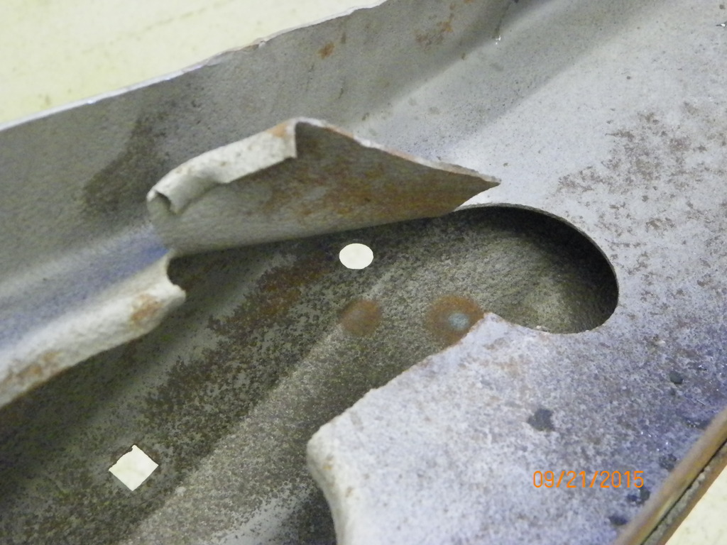
AFTER

BEFORE

AFTER
 10-25-2015, 09:03 PM
#210
TECH Regular
Thread Starter
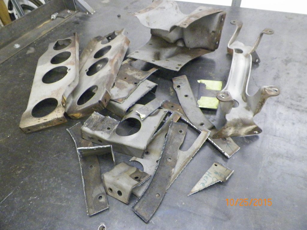
Now for the dreaded x brace. Here is the original assembly. There are aftermarket kits out there designed for overdrive transmissions, but the only ones I was able to find would still probably require modifications due to the motor being set back from the factory location. I am aware of one particular kit that allows some flexibility in the location it is mounted front to back, BUT I could not get the manufacturer to respond. I spent a couple of weeks trying to chase down the makers of the kit I wanted to purchase, but I was unsuccessful. They have probably retired and rode off into the sunset with the tooling sitting in the corner collecting dust .....oh well here goes plan B - build one.

.....oh well here goes plan B - build one.
Last edited by Kharp; 10-26-2015 at 01:30 PM.
10-25-2015, 09:08 PM
#211
TECH Regular
Thread Starter
Plan B - start cutting until the motor/trans will fit, and then come up with a design.

Last edited by Kharp; 10-25-2015 at 09:33 PM.
10-25-2015, 09:17 PM
#212
TECH Regular
Thread Starter
Here is the trimming required to get the tranny to fit. Ignore the one side support that was still there for the picture - it had to leave also. My thoughts are to design a cross member and frame connectors that will allow the transmission to be pulled without taking the motor out. I would also like to make the pieces look like they "belong there". This is going to require some careful planning.


Last edited by Kharp; 10-26-2015 at 06:17 AM.
10-25-2015, 09:25 PM
#213
TECH Regular
Thread Starter
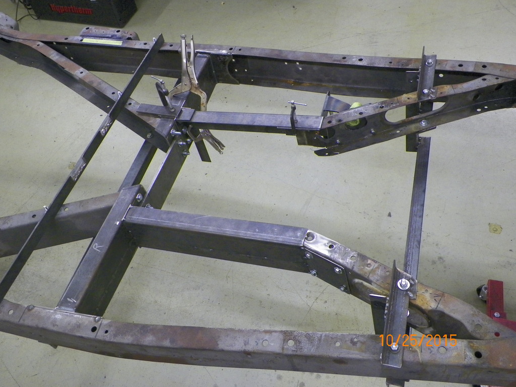
Here is the new layout under construction. Passenger side (lower portion of pic) is roughed in and drivers side in progress. The piece of plate in middle tying it together is just a temporary piece. I will make the real deal when the tranny finds its home. More pics and details soon...

Last edited by Kharp; 10-26-2015 at 01:31 PM.
10-26-2015, 06:52 AM
#214
As usual.........Perfectly thought out ...............Great Job !!! "Again".........
Ken
Ken
10-27-2015, 07:42 AM
#215
TECH Regular
Thread Starter
Thanks a lot Ken! I did have some help, but he seems to want to stay off the radar so I don't mention him often, but I definitely appreciate his help! By the way, I saw a car in this months Street Rodder magazine in a TCI advertisement that sure looks like your old Coupe. Could it be?


Last edited by Kharp; 10-29-2015 at 08:39 AM.
10-27-2015, 06:05 PM
#216
10-29-2015, 08:14 AM
#217
TECH Regular
Thread Starter
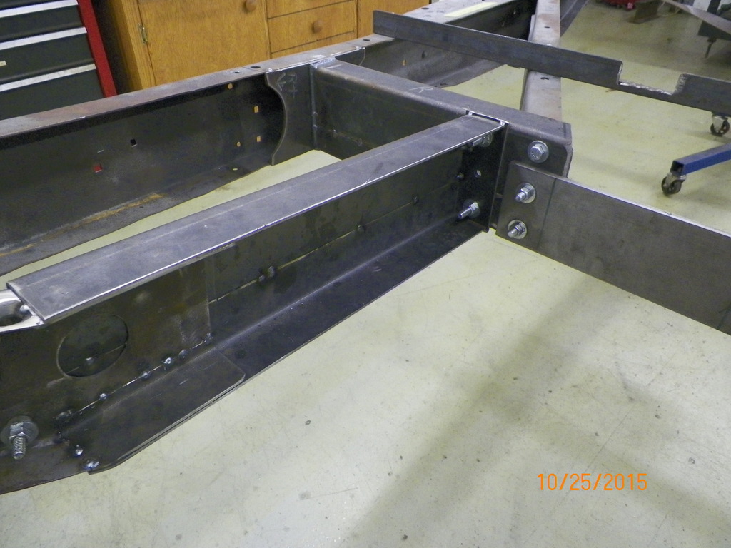
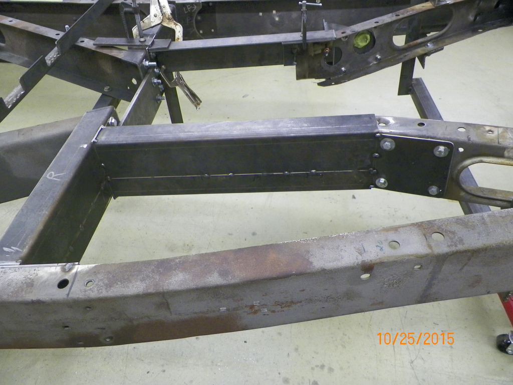
Here is a closer shot of some pieces for the new x brace assembly. They are only spot welded and don't have all the fasteners attached etc. In other words only "roughed in". Started with a small boxing plate on the outside frame rail. This will allow me to run wires and lines behind the boxing plate as well as have access to the running board factory mounting holes right behind the plate. Then I had some 10 gauge bent at 90 degrees to make some 2 x 3 angle iron. I couldn't find any material like this to buy that was thinner than 3/16", and that was thicker than it needed to be. The long 3" leg was then cut on an angle across so that when the top and bottom pieces are put together they form a piece of tapered channel. This was necessary because the x brace is not at the same level than the frame...the x makes a drop in the center of the car, so the channel needed to be wider at that point. Mounting flanges were put on the ends to tie the pieces together. The piece running toward the front of the car was done the same way splicing 2 pieces of angle together to form some channel just wide enough to fit around the existing frame.
 10-29-2015, 08:27 AM
#218
TECH Regular
Thread Starter
A look from the other side. In the event the transmission needs to be pulled, the piece running from the cross member to the existing frame can be unbolted to give more room for the tranny to drop straight down. The other side is under construction. I'll leave the temporary plate in the center until the transmission is located, and then I'll know how to build the center piece that will tie it all together. This has been a hurdle in the build, and I'm glad its starting to fall into place.
 10-29-2015, 07:10 PM
#220