


Awd, lsx, t56 scratch build.

Thread Starter
TECH Apprentice


Joined: Apr 2014
Posts: 305
Likes: 8
This post will be a VERY VERY VERY slow process, hopefully not but it's a side project of mine and between work and family, it'll be a long time before it done.
Anyways, I'm making this post as a pic saver and time line for myself.
Parts-
5.3 aluminum lm4 (eventually forged internals shooting for 600-800awhp)
C6 torque tube cut down to 17" including bellhousing.
C5 t56 with fbody main shaft with 3 1/2" cut off the end.
Trailblazer ss np120 transfer case
Trailblazer ss front diff (4.10)
Cobra 31 spline 8.8 rear diff (4.10)
Wheelbase- 103"
Trackwidth front and back- 70"
Roof line- 39" (just to be lower than gt40)
Ride height- 3.5"
It will be a full tubed 1.5" .095" Dom tubing. Hoping for under 2500lbs with me in it and full tank of gas.
Will be making my own body, Pagani zonda / lemans prototype similar design, haven't really drawn up the body yet.
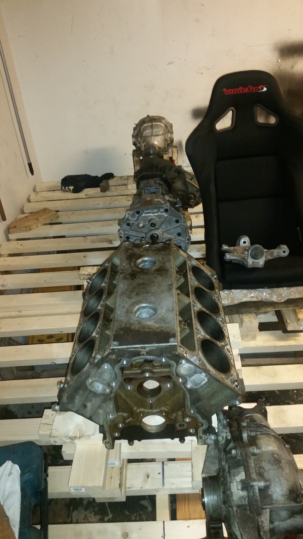
No more talking... pictures!!!
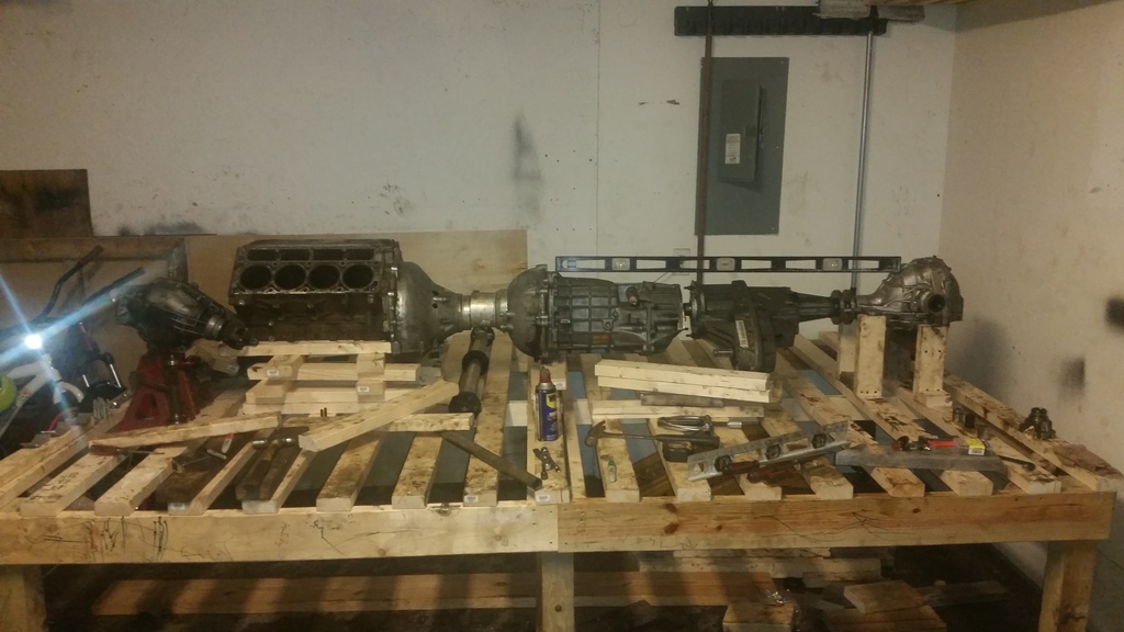
That's it for now. Between the rear diff and transfer case there will be a 1" poly bushing like a guibo. Also inside the torque tube, it'll have an approx 3" driveshaft with regular c5-c6 poly bushing on both ends.
Up next, I'll be picking up the dom tubing and getting a tube bender and starting the frame. Also, welding the shorten torque and finishing making a bracket from t56 to transfer case.
Anyways, I'm making this post as a pic saver and time line for myself.
Parts-
5.3 aluminum lm4 (eventually forged internals shooting for 600-800awhp)
C6 torque tube cut down to 17" including bellhousing.
C5 t56 with fbody main shaft with 3 1/2" cut off the end.
Trailblazer ss np120 transfer case
Trailblazer ss front diff (4.10)
Cobra 31 spline 8.8 rear diff (4.10)
Wheelbase- 103"
Trackwidth front and back- 70"
Roof line- 39" (just to be lower than gt40)
Ride height- 3.5"
It will be a full tubed 1.5" .095" Dom tubing. Hoping for under 2500lbs with me in it and full tank of gas.
Will be making my own body, Pagani zonda / lemans prototype similar design, haven't really drawn up the body yet.
No more talking... pictures!!!
That's it for now. Between the rear diff and transfer case there will be a 1" poly bushing like a guibo. Also inside the torque tube, it'll have an approx 3" driveshaft with regular c5-c6 poly bushing on both ends.
Up next, I'll be picking up the dom tubing and getting a tube bender and starting the frame. Also, welding the shorten torque and finishing making a bracket from t56 to transfer case.
Thread Starter
TECH Apprentice
Joined: Apr 2014
Posts: 305
Likes: 8
Never seen a wooden frame table?? Hah. That is my frame table, 100% leveled in all corners, all measurements are on the table and drivetrain is being mocked up leveled and at riding height, both front and rear diffs are at wheelbase. Those pics just show a quick mock up since I just cut the torque tube yesterday, once it's all mated, I'll make it a more solid mock up platform and start with the tubing.
The TBSS front is the regular 7.2 IFS used in lots of stuff right? Have you found any limited slips for those? Ive looked and looked and there isn't anything made. At one time there were Lock-Rites but they stopped making those even. Great project, keep us updated.
Thread Starter
TECH Apprentice
Joined: Apr 2014
Posts: 305
Likes: 8
Yea the front diff is used in more applications but I wanted the ss one due to the 4.10 gears. I haven't found limited slip for it though, unfortunately.
Thread Starter
TECH Apprentice
Joined: Apr 2014
Posts: 305
Likes: 8
Trending Topics
That won't suffice as a frame table.... but this is going to be a cool project!
My buddy built his own frame table and it was a ton of work. Wood flatness will change with humidity.....
Obviously not everyone can build/justify a frame table like this....
My buddy's setup: 6'x20' piece of half inch plate steel. Large I beam down the center and at the ends and 2"x4" tubing for the outer frame rails. It has levelling feet every few feet as well.
Bought a magnetic base drill press just for the job of drilling 490+ holes and tapping them to 3/8 coarse thread. Funny fact... a friend of mine ran the numbers on how much the material weighed that we drilled and tapped out of the plate and it came to 100lbs.
Last edited by gnx7; Dec 5, 2015 at 01:26 PM.
LS1 Tech Stories
The Best V8 Stories One Small Block at Time

6 Common C5 Corvette Failures and What's Involved In Repairing Them
Pouria Savadkouei
Retro Modern Bandit Pontiac Trans AM Comes With Burt Reynolds' Autograph
Verdad Gallardo
Top 10 Greatest Cadillac V Series Performance Models Ever, Ranked
Pouria Savadkouei
Top 10 Most Powerful Chevy Trucks Ever Made!

Hennessey's New Supercharged Silverado ZR2 Has 700 HP
Verdad Gallardo
Coachbuilt N2A Anteros Is an LS2-Powered C6 Corvette In Italian Clothes
Verdad Gallardo
Awesome K5 Blazer Restomod Comes With C7 Corvette Power
Verdad Gallardo
10 Camaros You Should Never Buy

10 LS Engine Myths That Refuse to Die
Verdad Gallardo Thread Starter
TECH Apprentice
Joined: Apr 2014
Posts: 305
Likes: 8
A table like that would be amazing if i were to build more than one car, eventually I'll probably end up making a decent 2x4 steel table or something similar. I only have $50 into this table since I had the wood in the garage. If I notice it warping due to humidity, then I'll upgrade.


Thread Starter
TECH Apprentice
Joined: Apr 2014
Posts: 305
Likes: 8
Update! And my first problem!( I'm sure of many)
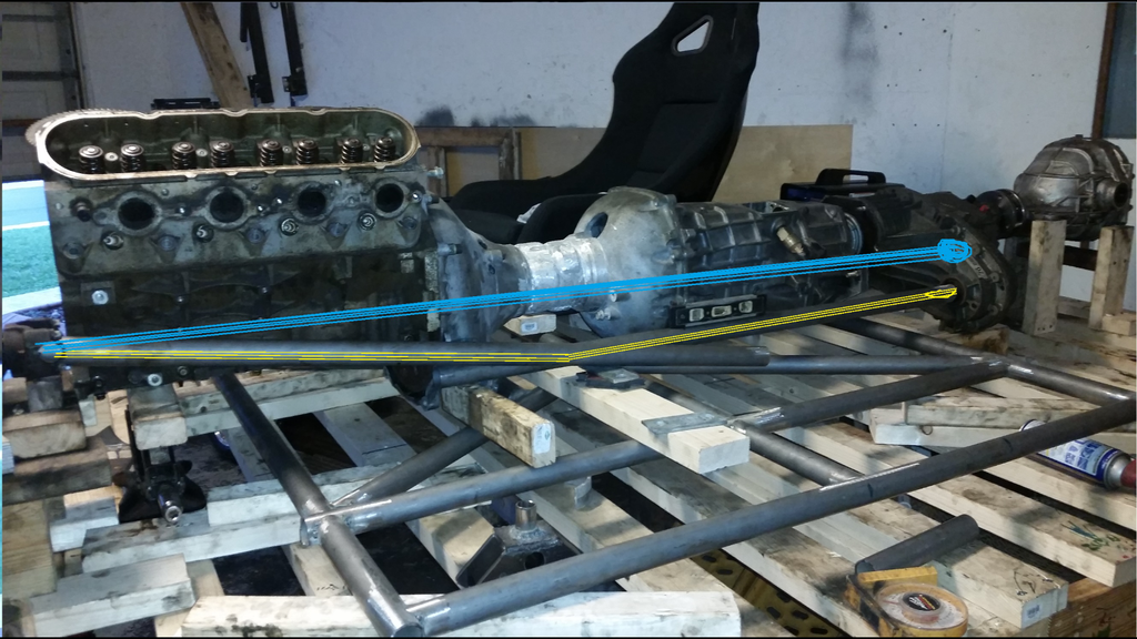
So I started doing the cockpit floor and ran into my first dilemma. My front driveshaft will have to be roughly 67-69" long and it will need to be a 2 piece to be able to have a critical speed of 200+mph. It'll only see 350 hp (if i decide to go up to 1000hp) . Anyway, the yellow is how I'd LOVE for it to be, with carrier bearing right in front of the inclined section. It'll hAve to go up ~10� , and I'm afraid that wouldn't be good for the high critical speed. The blue line is obviously a straight shot (that's with swinging the transfer case up until it's parallel with the ground) but I'll have to put my seat about 7-9" high off the floor making the height of the car 44-45" off the ground. It's still low, roughly a vette height but if I could somehow get away with the (yellow line) way, I could keep my seat down low and keep my roof height at 39".
I emailed DSS and they told me the 10� incline might cause a problem so I'm guessing I'll have to go with the straight shot way.
Anyway, anyone running a high angle driveshaft with any success?
TECH Addict
Joined: Jul 2013
Posts: 2,189
Likes: 123
From: Portland, Oregon
Very cool concept, but yes, why use the torque tube if AWD is the goal?
Could you run the front driveshaft directly under the engine if you were to use a low profile dry-sump oil pan?
Definitely keep us posted.
Could you run the front driveshaft directly under the engine if you were to use a low profile dry-sump oil pan?
Definitely keep us posted.