When you click on links to various merchants on this site and make a purchase, this can result in this site earning a commission. Affiliate programs and affiliations include, but are not limited to, the eBay Partner Network.
Controlling Vintage Air Surefit Gen IV with LS Gen III Vortec PCM
I've been brainstorming all afternoon on A/C options for my 8.1L swap. I think I've got a way to run the Vintage Air system compressor through the Vortec Truck PCM, but I wanted to throw it out for critique before I do any wiring.
Background:
-Donor Engine: L18 Vortec 8100 out of 2004 C4500 Medium Duty Truck
-Recipient: 1986 C20 Suburban with Vintage Air Gen IV Surefit system.
Problem: It would be really easy to just run the Vintage Air as a standalone unit. However, I'd like to control the compressor with the Vortec PCM, as it includes high RPM and WOT shut off capability.
Analysis:
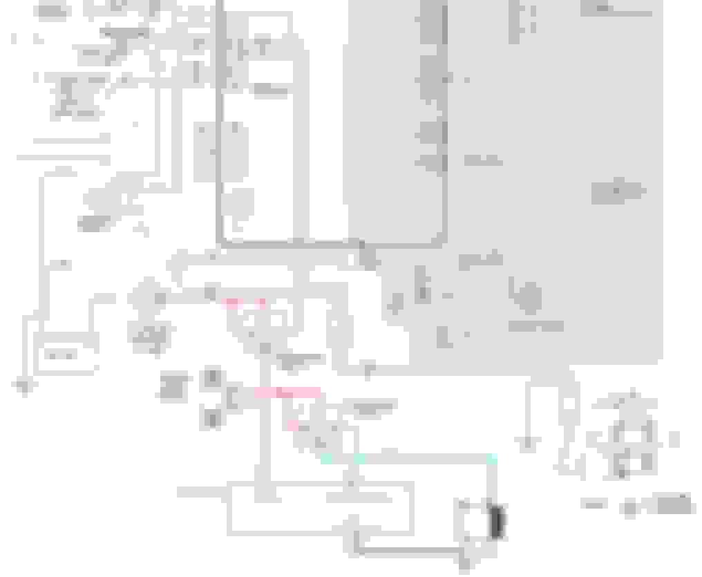
1) The Vintage Air System uses a relay to apply 12V to the A/C compressor clutch from a 30A circuit breaker. The relay signal comes in the form of a ground signal via a blue wire from the Vintage Air ECM to Pin 30 on the Vintage Air Compressor Relay. When the Vintage Air ECM commands the relay on, the relay sends a 12V signal via a blue wire through the high/low pressure trinary switch to the Vintage Air compressor. If the A/C pressure is either too high or too low, the trinary switch does not pass the signal, thus the A/C clutch remains disengaged. This circuit is shown below:
2) The factory HVAC system in the '04 C4500 works like the 99-02 Vortec Gen III trucks (03-up trucks have a much different pinout that is not very swap friendly). The A/C request signal is a +12V signal sent from the HVAC controls through the normally closed High Pressure Switch to C2 Pin 17 on the PCM. The PCM also looks at a normally open ground switch at C2 Pin 55. If the system has adequate pressure, the switch closes, supplying a ground to the PCM. If the PCM sees a +12V A/C request at Pin 17(A/C is being requested and the pressure is below the upper limit), and a ground signal at Pin 55 (pressure is above the lower bounds), and passes its internal PCM checks to enable the compressor clutch, a ground is sent via C2 Pin 43 to the A/C compressor relay. When grounded, the relay provides +12V to the clutch, causing it to engage. This circuit is shown below with annotation:
Proposed Solution:
Using a second relay between the Vintage Air Relay and the A/C compressor to allow PCM control. The +12V output of the activated Vintage Air Relay would be sent through the Trinary Safety Switch to the +12V A/C request input at C2 Pin 17. The output from the Vintage Air Relay would also be used to provide power to a 2nd Relay, which uses the PCM Clutch Enable Relay output as the ground signal to activate the relay. The output from this second relay would then be used to provide +12V to the Compressor Clutch. C2 Pin 55 would be connected directly to ground, bypassing the low pressure switch protection, since this protection is already provided by the Trinary Switch. The proposed modified diagram is shown below:
My Main Concerns
1) Am I interpreting the inputs and outputs from the PCM correctly?
2) Can I use the output from Relay 1 to power Relay 2, or does it need a completely separate connection back to the 30A circuit breaker, independent of Relay 1?
3) Can I simply connect C2 Pin 55 to ground, or do I need to add in some sort of switch or resistor inline?
4) Am I in any danger of sending to much amperage to the A/C request at C2 Pin 17 and frying the PCM?
5) Am I missing something completely obvious after thinking about this all day?
I'd be interested on anyone's input. I searched and read a good bit on the topic, but most of the swaps that have done anything like what I'm trying to do used either factory air conditioning, or a F-body/Corvette PCM calibration which is set up for a different style pressure switch. Thanks in advance for the help.
Your approach seems reasonable to me. On #4 - amperage isn't "sent" anywhere; rather, the device consuming the power tries to "pull" the amount of current required. I've gotta think the circuit responsible for A/C request pulls a very minimal amount of current once that wire has 12V+ on it from the pressure switch. On any other connections, if you're worried about back-feeding something that you don't want back-fed, put a properly sized diode in that line.....only lets the current flow one way, like a check valve.
If you are positive the AC request is an input, then your circuit works....conventional relay logic....I like the approach, where did you find the pin out?
Hey guys I hope I�m doing this right .. I�m new to all this but could really use the help .. I�m building a 1957 gmc truck with a 08 5.3 chevy engine I have a stand-alone harness with no ac recognition .. trying to figure out to wire the vintage air system with my electric fan .. if anybody can help I would greatly appreciate it ..
Hey guys I hope I�m doing this right .. I�m new to all this but could really use the help .. I�m building a 1957 gmc truck with a 08 5.3 chevy engine I have a stand-alone harness with no ac recognition .. trying to figure out to wire the vintage air system with my electric fan .. if anybody can help I would greatly appreciate it ..
Both the VA trinary switch and LS ecu provide a ground to the fan relay. I wired both the trinary and ecu to ground the same relay. That works but some have indicated the grounding of the trinary can cause a CEL from the fan circuit.
Search "trinary" here, you'll find schematics.
Originally Posted by Glasshouse 75
yes I know I already have that .. I�m just not sure how to wire it all to work together


 10-08-2017, 06:45 PM