

1970 GTO Version 3.0


Thread Starter


Joined: Mar 2003
Posts: 10,605
Likes: 1,881
From: Little Austin
I actually took the plate to the garage earlier today and kind of looked at where they might go. The bulkheads have an o-ring on the backside, so when they are screwed down against the panel they should seal nicely.
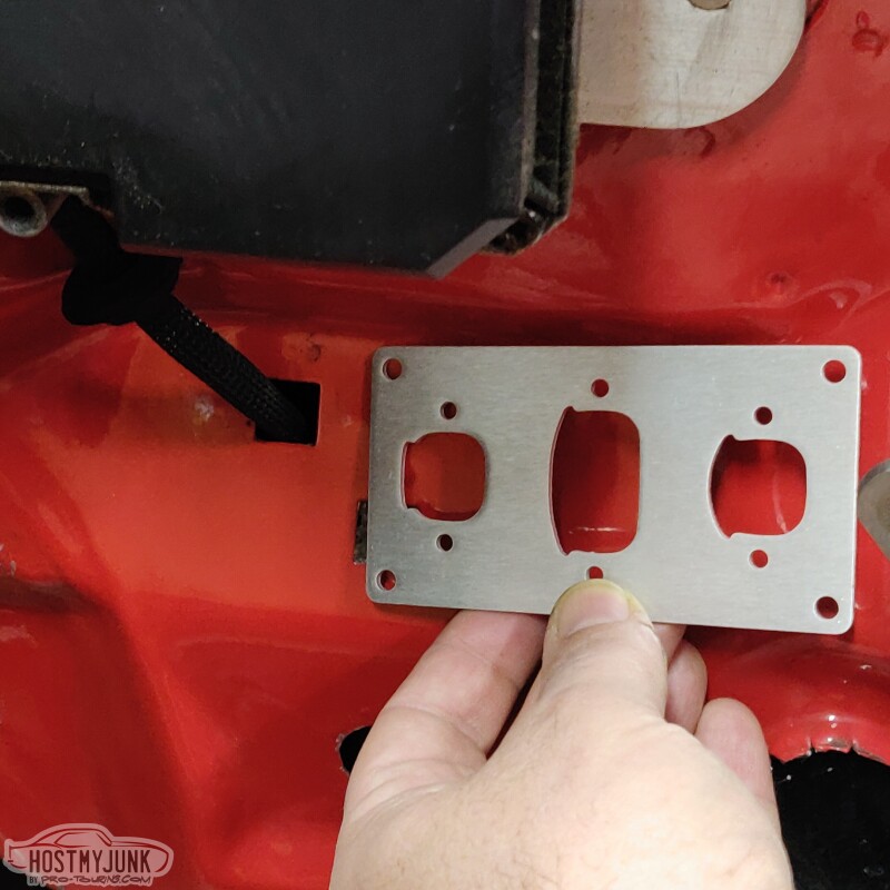
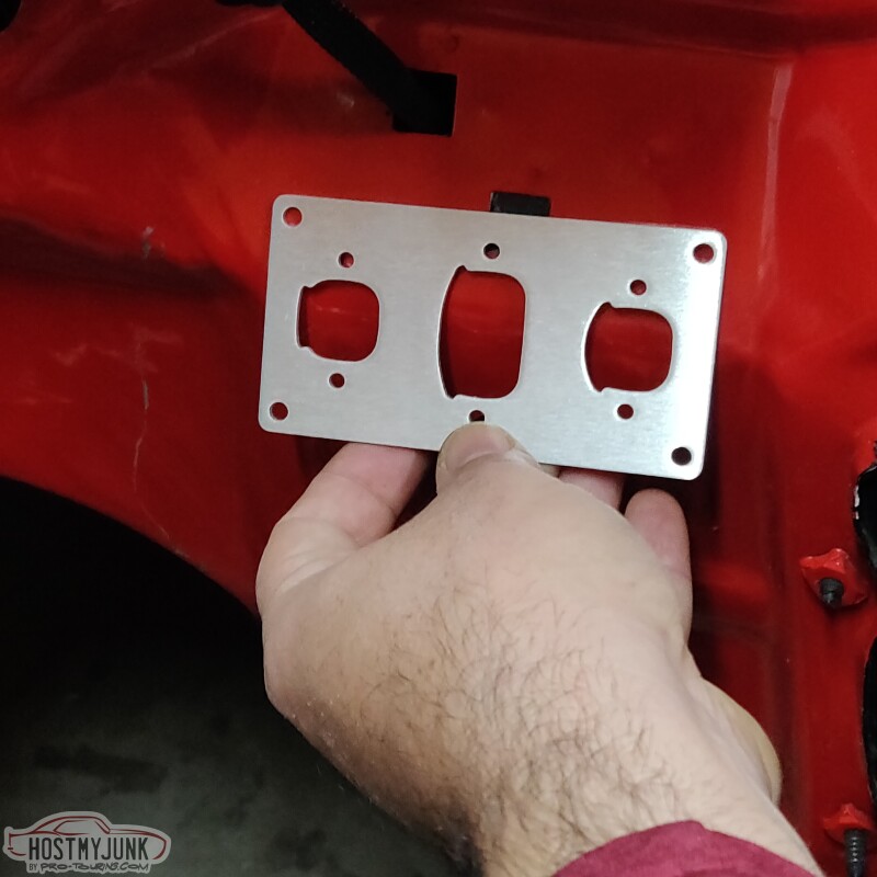
I am thinking they will fit perfectly here:
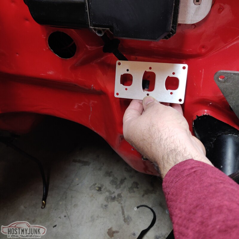
I will reroute the wiring for the wiper motor somewhere else. Maybe to the grommet just below, where my hand is covering some of it.
This is a picture from when we were taking the engine out. It gives you an idea of where the plate would go, just below the wiper motor.
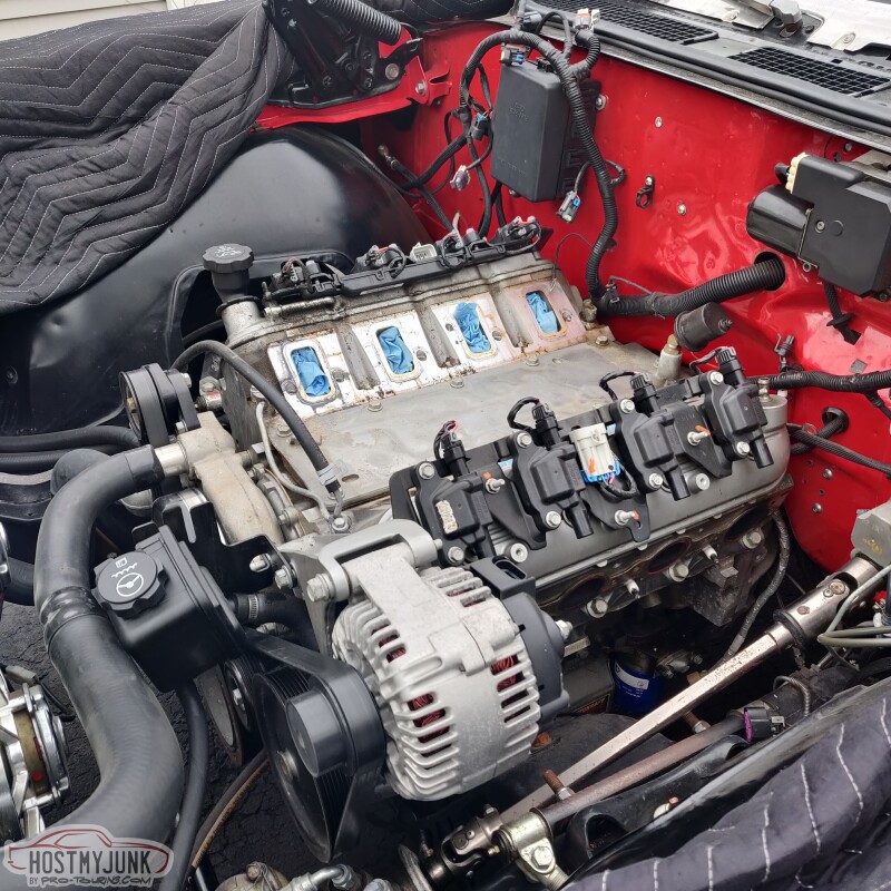
These 3 connectors are not for the whole engine harness. The center connector is for the injectors and the smaller ones on the side are for the coils. The rest of the harness will pass through the big hole to the left, where the old harness is in the picture above.
Andrew
I am thinking they will fit perfectly here:
I will reroute the wiring for the wiper motor somewhere else. Maybe to the grommet just below, where my hand is covering some of it.
This is a picture from when we were taking the engine out. It gives you an idea of where the plate would go, just below the wiper motor.
These 3 connectors are not for the whole engine harness. The center connector is for the injectors and the smaller ones on the side are for the coils. The rest of the harness will pass through the big hole to the left, where the old harness is in the picture above.
Andrew


Thread Starter
Joined: Mar 2003
Posts: 10,605
Likes: 1,881
From: Little Austin
Andrew
Thread Starter
Joined: Mar 2003
Posts: 10,605
Likes: 1,881
From: Little Austin
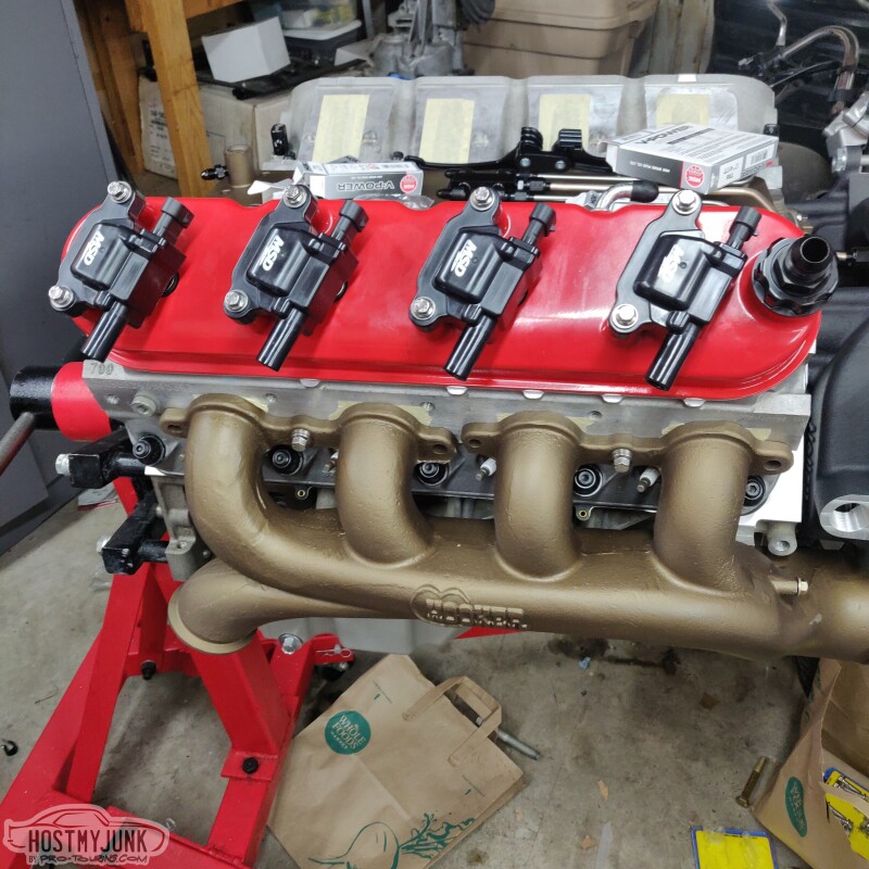
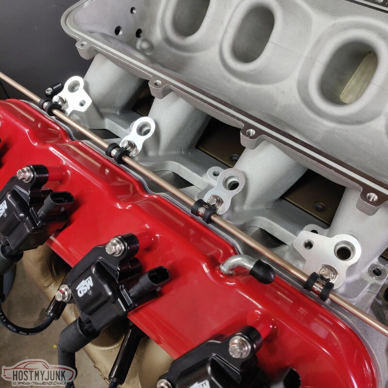
Did a little more mock-up. I was a little worried about the coils and Accel wires playing nicely together with the turbo manifold.
Spark plug access is amazing, which is really nice for quick plug checks.
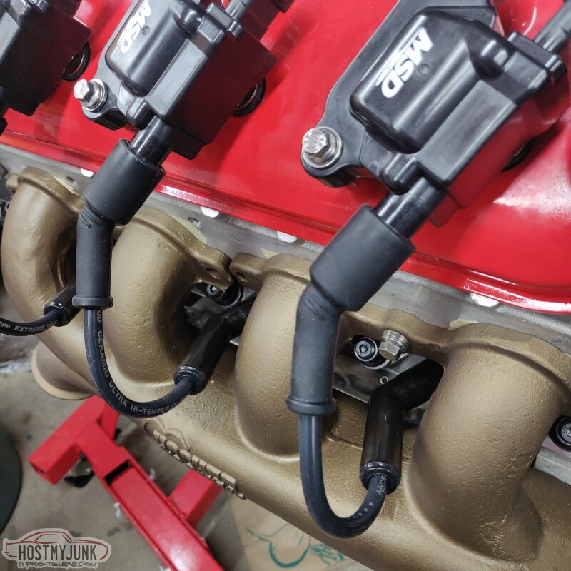
Cylinders 2 and 4.
Cylinders 6 and 8.
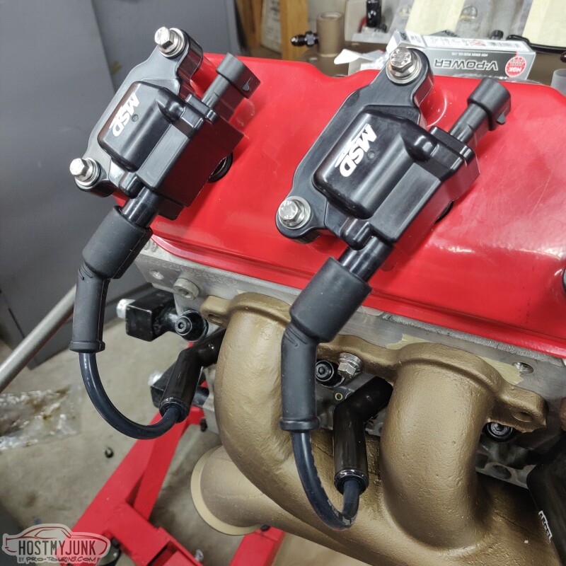
There is a solid 1/2" gap between the ceramic plug boots and the manifold runners.
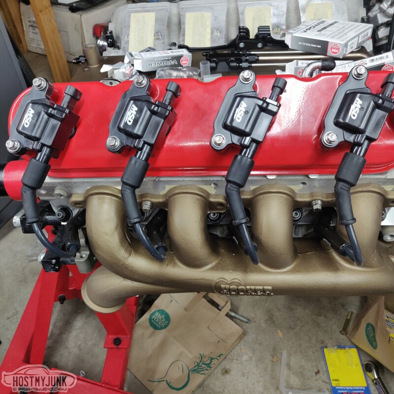
Overall, this is looking promising. It remains to be seen how the downpipes will effect any of this.
Andrew
Spark plug access is amazing, which is really nice for quick plug checks.
Cylinders 2 and 4.
Cylinders 6 and 8.
There is a solid 1/2" gap between the ceramic plug boots and the manifold runners.
Overall, this is looking promising. It remains to be seen how the downpipes will effect any of this.
Andrew


Did a little more mock-up. I was a little worried about the coils and Accel wires playing nicely together with the turbo manifold.
Overall, this is looking promising. It remains to be seen how thedownpipes 5" Hole saw to the front fender will effect any of this.
Andrew
Overall, this is looking promising. It remains to be seen how the
Andrew
Thread Starter
Joined: Mar 2003
Posts: 10,605
Likes: 1,881
From: Little Austin
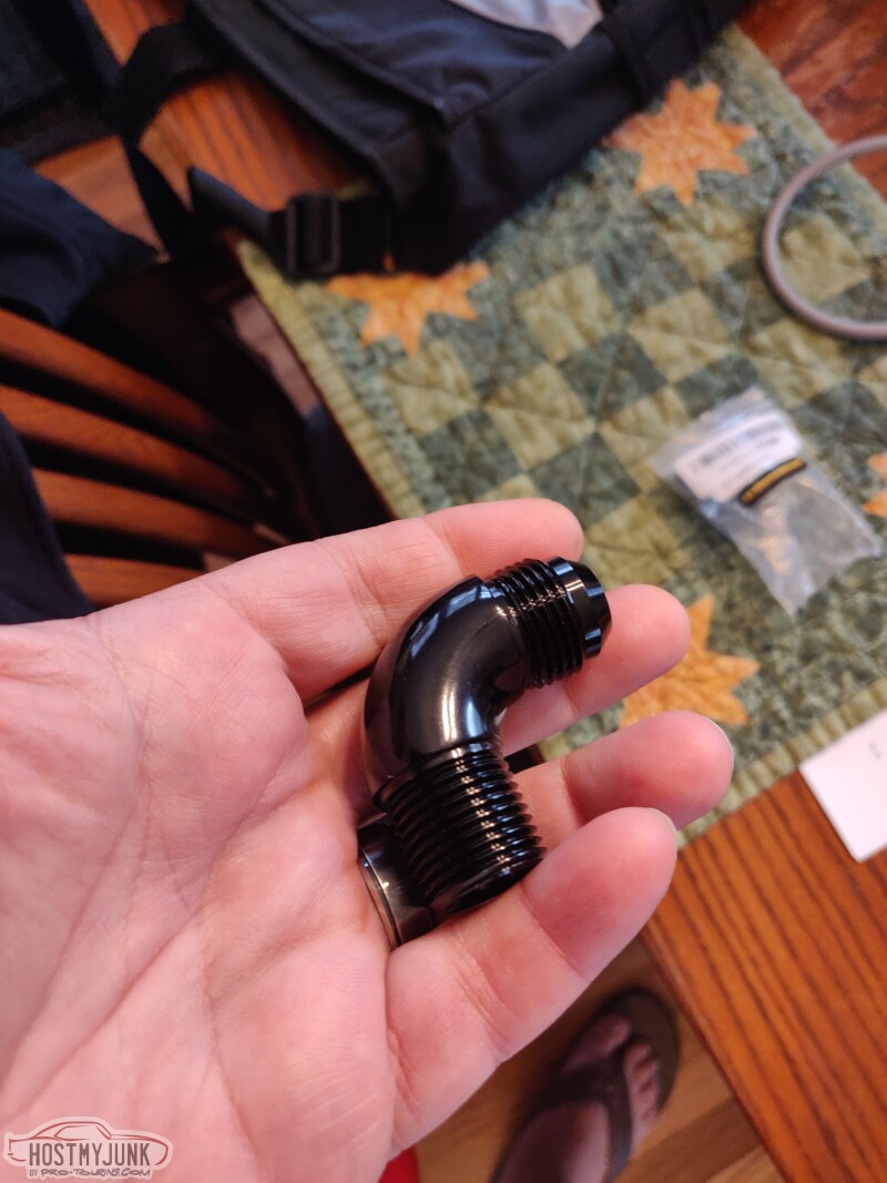
Since I am back to looking at the oil pan for turbo drain, I found this smooth 90 degree fitting on Amazon. I will probably still have to pull the pan to install it, but hopefully that will be the last time!
I also got my first order from Stainless Bros for the turbo up-pipe. I was very impressed that they had everything that needed in stock and it shipped the same day. I placed my order on Monday afternoon and got my parts Wednesday afternoon. I was also pleased to see that everything was thoughtfully bagged and well packaged.
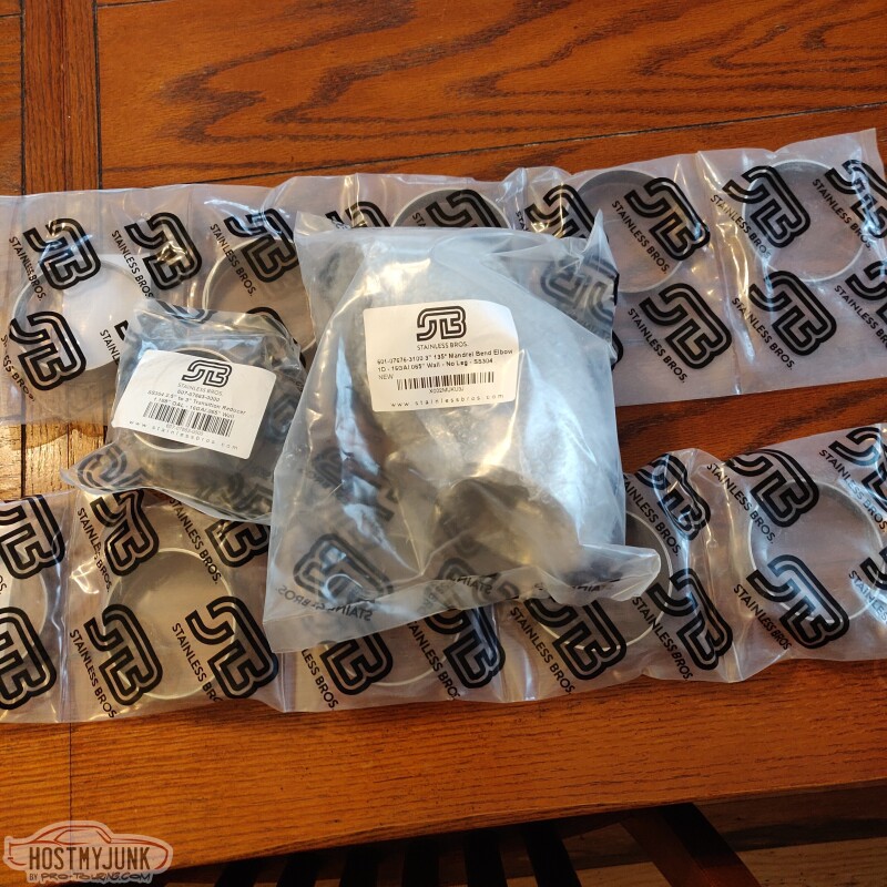
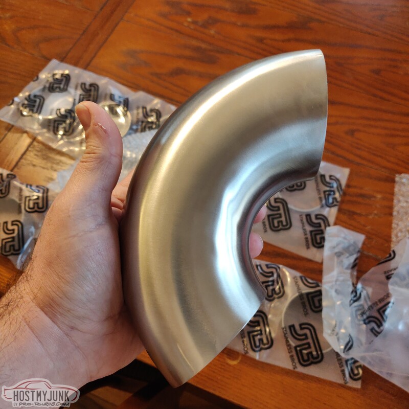
This is a 3" 135 degree bend that will go on the manifold exit.
I also got some precut pie-cuts that will be used to snake around and place the turbo where I want.
Andrew
I also got my first order from Stainless Bros for the turbo up-pipe. I was very impressed that they had everything that needed in stock and it shipped the same day. I placed my order on Monday afternoon and got my parts Wednesday afternoon. I was also pleased to see that everything was thoughtfully bagged and well packaged.
This is a 3" 135 degree bend that will go on the manifold exit.
I also got some precut pie-cuts that will be used to snake around and place the turbo where I want.
Andrew

On The Tree
Joined: Nov 2021
Posts: 127
Likes: 74
Pieces all look like good quality. Those pie cuts will certainly come in handy.
I've saw people literally use a punch to install turbo drain fitting while the pan was still on the motor. Personally, I'd take the pan off but that's just me haha.
I've saw people literally use a punch to install turbo drain fitting while the pan was still on the motor. Personally, I'd take the pan off but that's just me haha.
Thread Starter
Joined: Mar 2003
Posts: 10,605
Likes: 1,881
From: Little Austin
Andrew
Thread Starter
Joined: Mar 2003
Posts: 10,605
Likes: 1,881
From: Little Austin
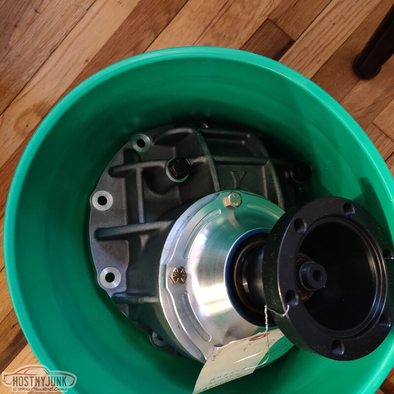
Quick Performance finally sent me that remainder of the rear end parts. Yes, they shipped the carrier in a Menards bucket, which was then packed in a really heavy duty cardboard box. No complaints, just found it funny. It's a Yukon bolt through aluminum carrier with an Eaton 35 spline TruTrack and 3.25 gears, plus the CV pinion yoke, which I sent them.
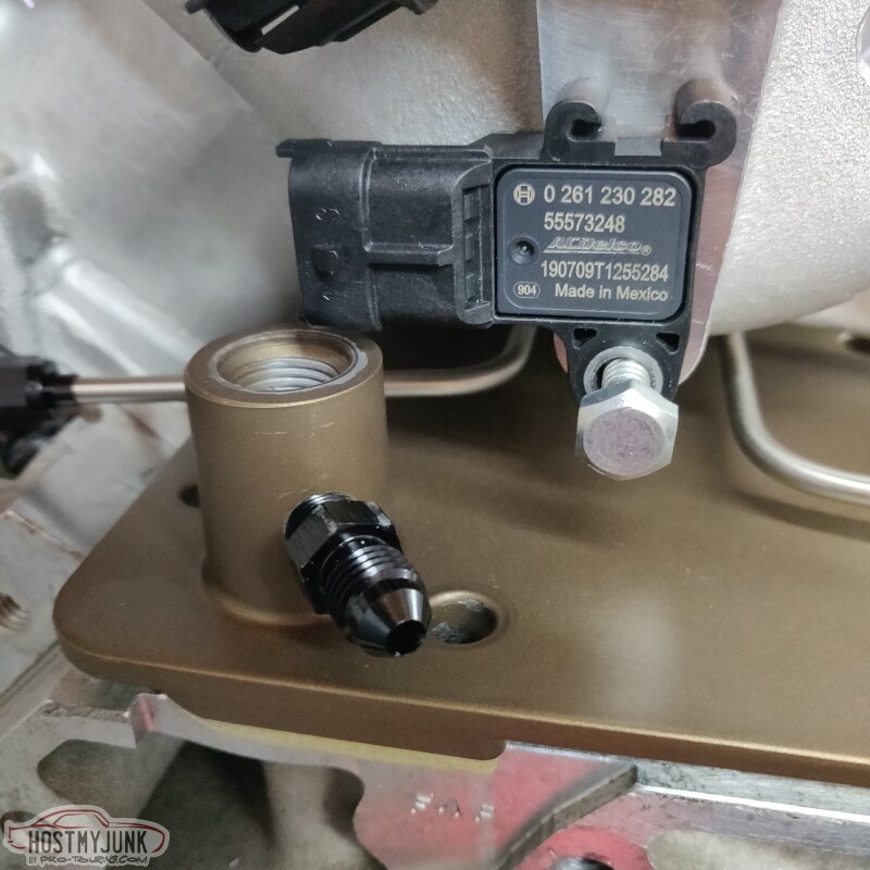
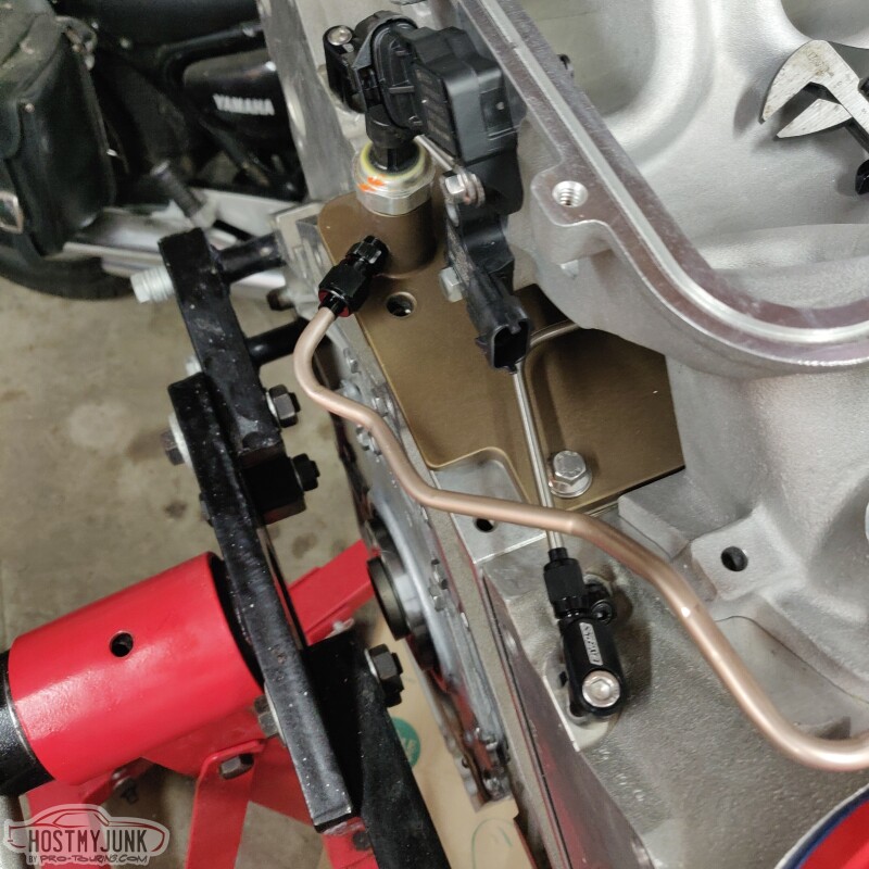
I've also been keeping Vic busy with small machining projects. He used some really heavy duty loctite to install a 3/8" NPT plug into an existing port in the intake manifold, then drilled it out to a 12mm hole. This is for the Bosch TMAP that I will be using as the main vacuum/boost sensor for the Holley EFI.
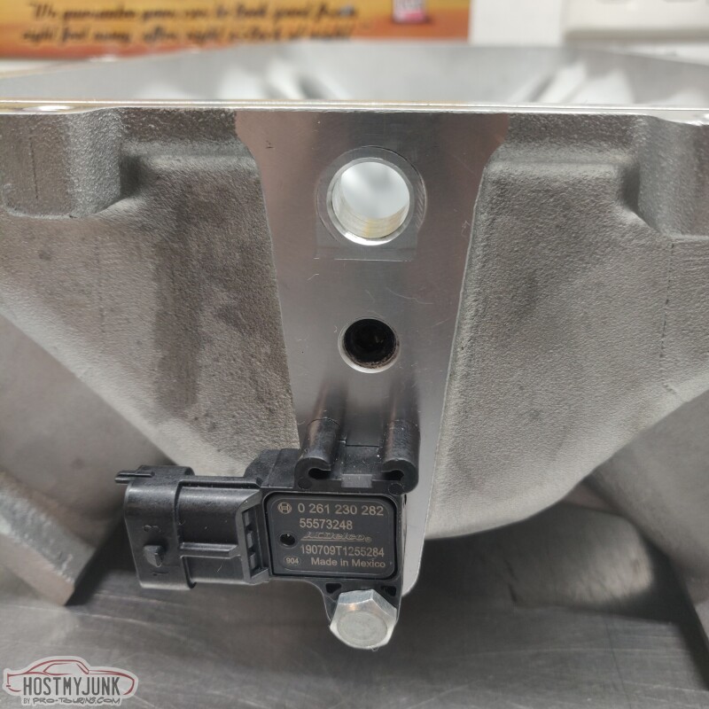
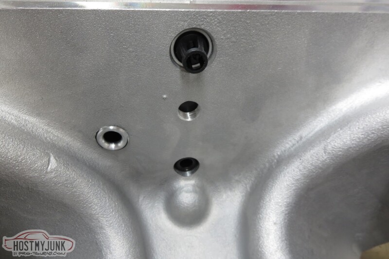
The MAP sensor below it is for the VaporWorks fuel pressure controller. It will adjust rail pressure based on vacuum and boost to maintain a consistent deferential pressure across the injectors. He also added a port for the vacuum line that will go to the catch can.
He is also going to drill and tap little holes for P-clamps that will hold the oil feed line for the turbo.
Andrew
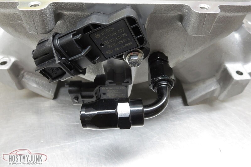
I've also been keeping Vic busy with small machining projects. He used some really heavy duty loctite to install a 3/8" NPT plug into an existing port in the intake manifold, then drilled it out to a 12mm hole. This is for the Bosch TMAP that I will be using as the main vacuum/boost sensor for the Holley EFI.
The MAP sensor below it is for the VaporWorks fuel pressure controller. It will adjust rail pressure based on vacuum and boost to maintain a consistent deferential pressure across the injectors. He also added a port for the vacuum line that will go to the catch can.
He is also going to drill and tap little holes for P-clamps that will hold the oil feed line for the turbo.
Andrew
Thread Starter
Joined: Mar 2003
Posts: 10,605
Likes: 1,881
From: Little Austin
Andrew
Thread Starter
Joined: Mar 2003
Posts: 10,605
Likes: 1,881
From: Little Austin
This morning Vic sent me a few mock up pictures of the new radiator (I had to get a new one...long story) with all of the tabs ready to weld. The tabs on the radiator will hold the fans, heat exchanger for the A2W intercooler, and the AC condenser.
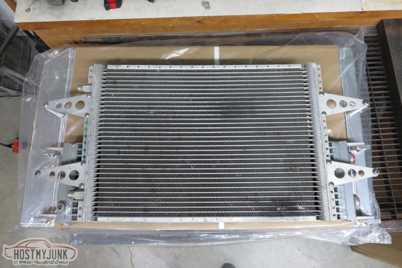
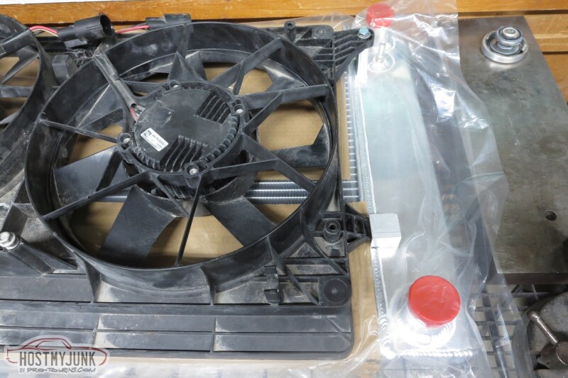
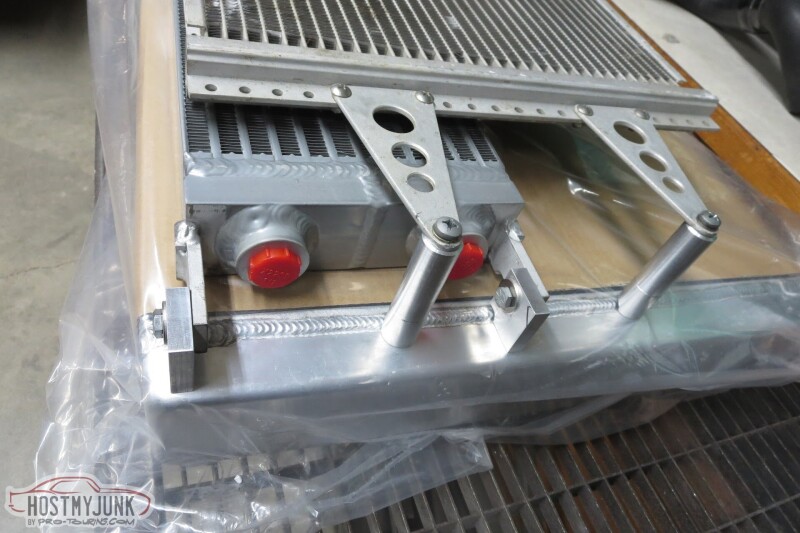
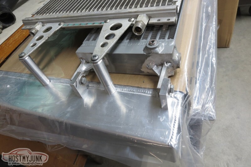
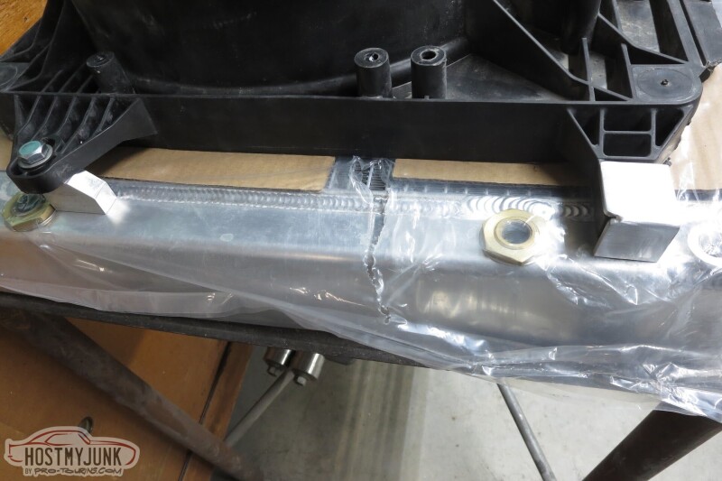
Progress is being made.
Andrew
Progress is being made.
Andrew
Thread Starter
Joined: Mar 2003
Posts: 10,605
Likes: 1,881
From: Little Austin
Some of my friends rag on me for not dropping the engine in the car, but this is the kid of stuff that is so much easier to deal with when the engine is still on the stand. This situation is on Holley. Not sure what their thinking was...
This situation is on me...::facepalm::
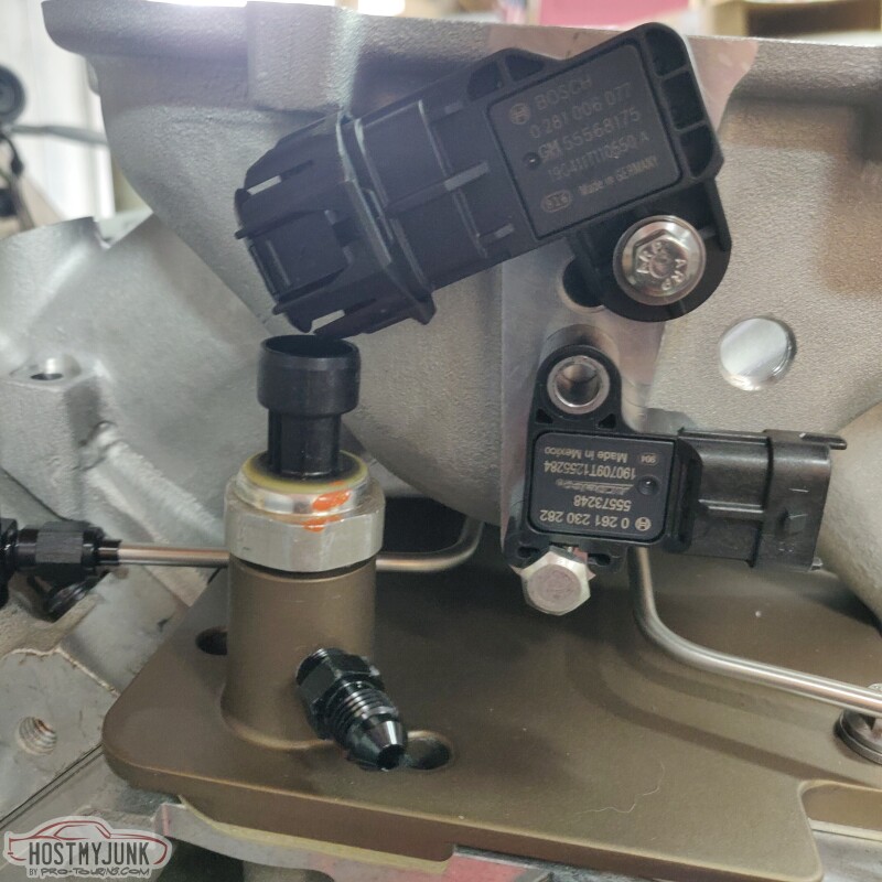
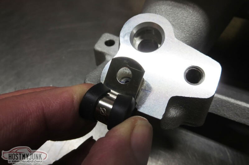
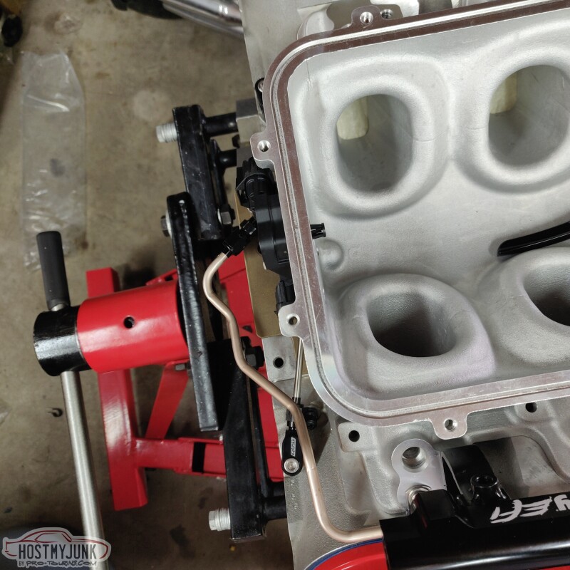
The added holes for the P-clamps turned out really well. I like the look and how the oil feed line for the turbo will be well supported.
This is with the fuel rail fitted.
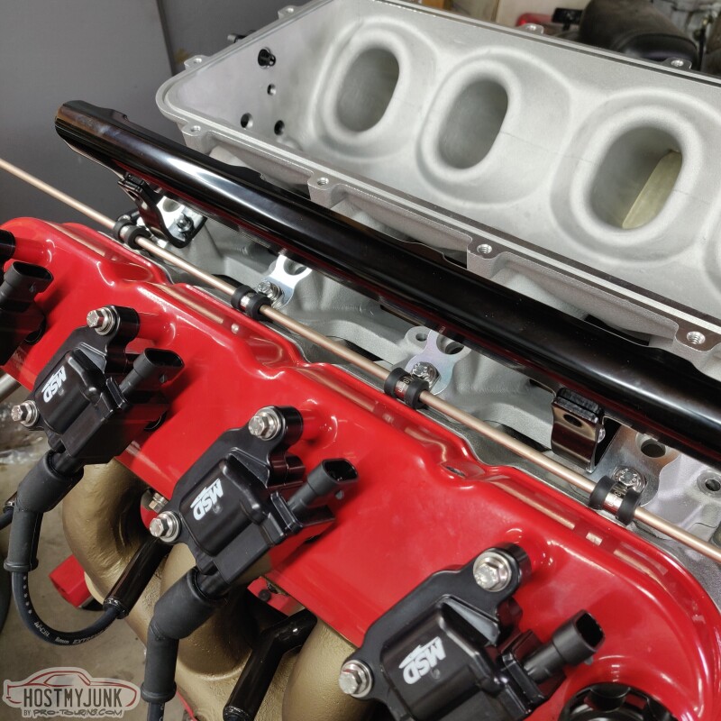
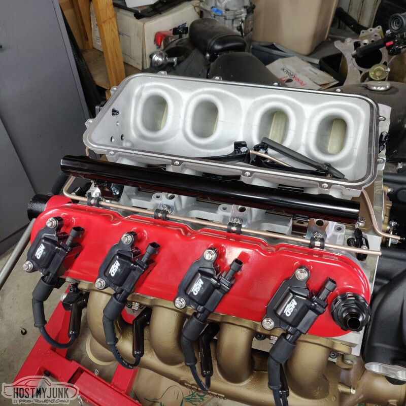
Hopefully this oil feed line routing doesn't cause any issues.
Andrew
This situation is on me...::facepalm::
The added holes for the P-clamps turned out really well. I like the look and how the oil feed line for the turbo will be well supported.
This is with the fuel rail fitted.
Hopefully this oil feed line routing doesn't cause any issues.
Andrew