When you click on links to various merchants on this site and make a purchase, this can result in this site earning a commission. Affiliate programs and affiliations include, but are not limited to, the eBay Partner Network.
This has been an awesome build to follow and we appreciate your patronage throughout it! You have detailed updates good/bad with quality images to showcase the progress of the build. We like that you're using one of our HD Dual Seal Clamps for the compressor discharge. These are robust clamp assemblies that allow for movement/misalignment. Using them on the compressor discharge is a great way to showcase how they can be used. We'll be sure to continue following along on this impeccable build
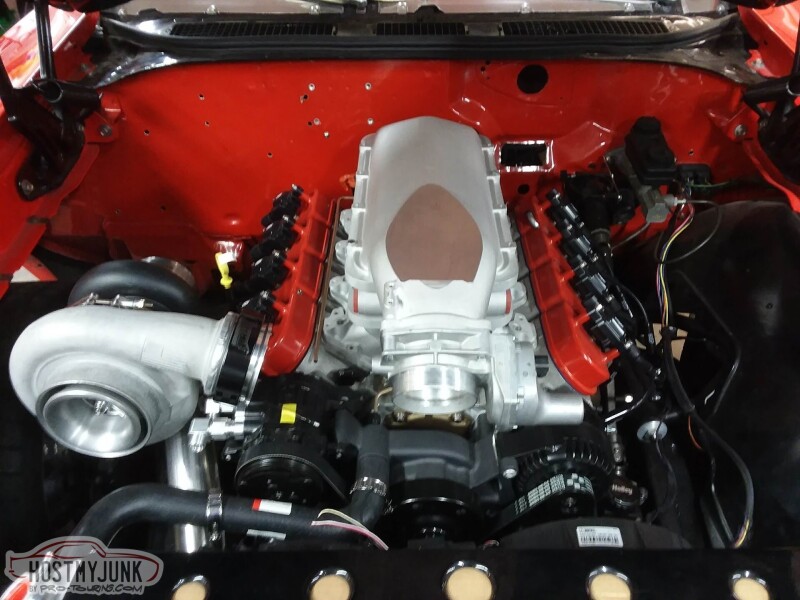
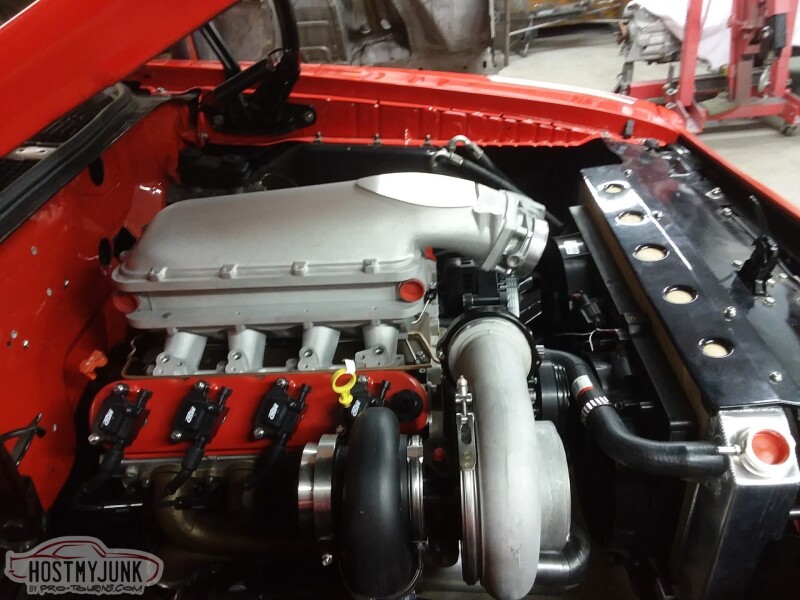
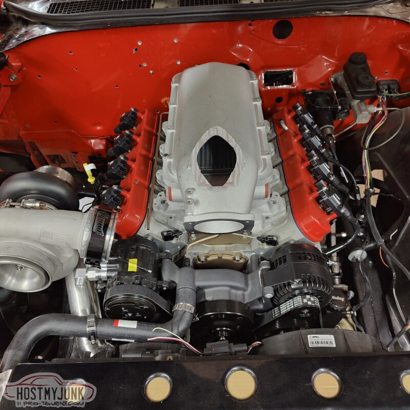
Thanks for the kind words. This build also features the 8715R1 Ghost Cam and whatever springs and pushrods that you guys recommended
Not to mention a bunch of small parts that keep having to get, like this long -10 ORB fitting for the oil drain, and so much more!
This morning I spent a few hours trying to help a local customer with a Coyote no-start issue, so I didn't have time mess with the car. But Vic sent me these pictures in the afternoon.
I think as far as looks go, it looks pretty good.
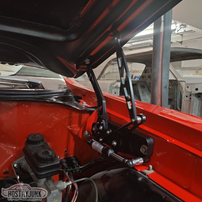
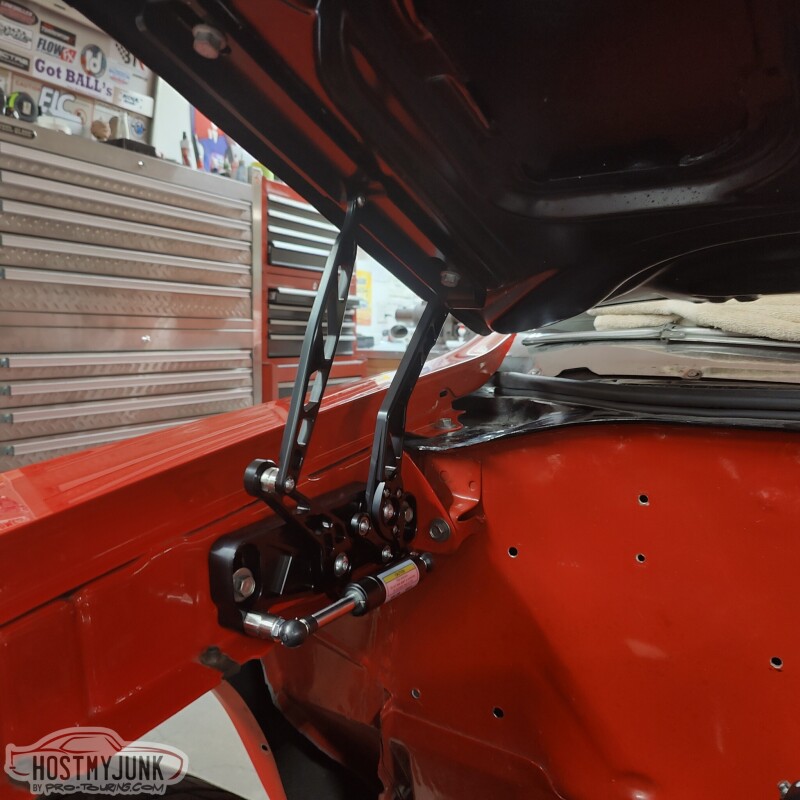
Tomorrow I will have a chance to go se it in person and see what kind of clearance there is with the hood. We are also going to install the Ring Brothers billet hinges, just to make sure everything fits the way it should.
Before we finalized the intake, we thought it would be good to install the new Ring Brothers hinges. These are very well made and have plenty of adjustment to get the hood lined up well.
Installing them was a simple remove and replace operation and after a bit of fiddling with the adjustment, the hood was closing better than it ever has before. We did notice that these hinges don't allow the hood to open as much as the stock hinges. I guess this was mentioned on the Ring Brothers website, but I somehow missed it. I really don't think it will cause any issues...
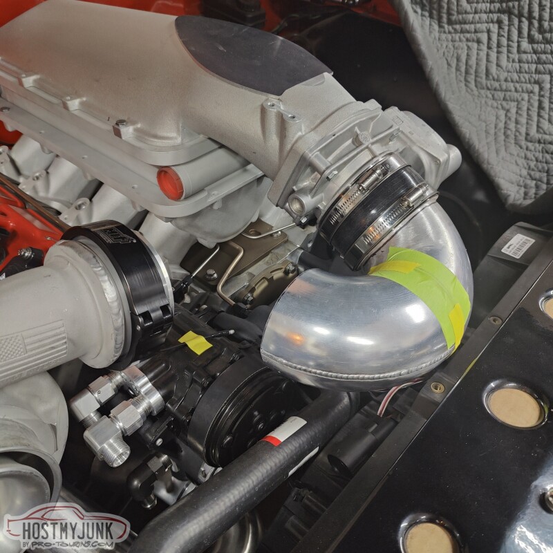
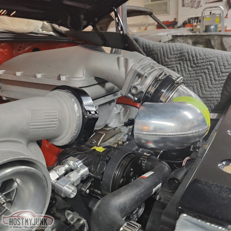
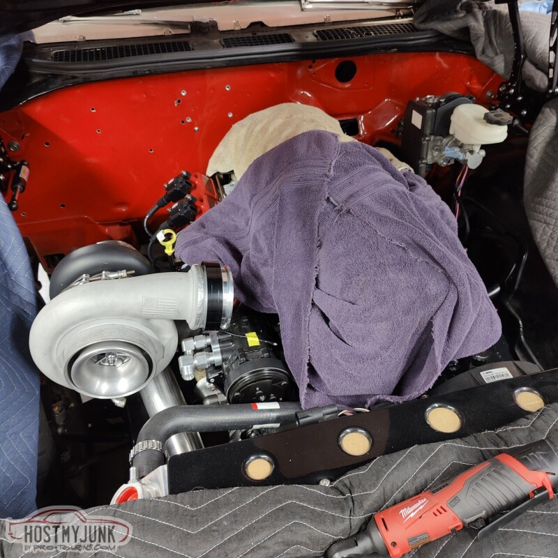
Now that the intake was finalized it was time to keep working on the charge pipe from the compressor outlet to the throttle body.
We ended up cutting the 180 degree bend that we had made previously so that half of it could be clocked independently.
This gave us a more clear path to the compressor, so all that is left is to add another 90 and a couple of small straight cuts to make it all fit.
It is a bit of a tortured path, but this is why we chose to stay with 4" piping to keep the pressure drop to a minimum. It is really no more elaborate than if there was an A2A intercooler in the front and we had to make all the associated pieces to work with that. I think this looks super clean too.
Happy New Year to Everyone and thanks for following along.
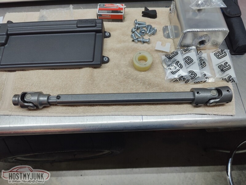
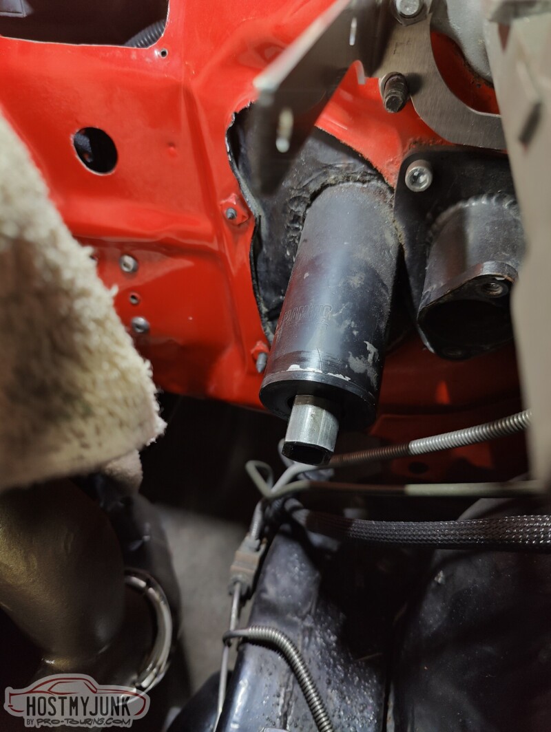
One of the items to replace for this update was the steering shaft. There was nothing wrong with it, but I never liked that it was a solid shaft.
This is a collapsable shaft and new u-joints from Borgeson. I will also be replacing my 20 year old AGR steering box with one from Borgeson.
In this picture the shaft is is already trimmed to fit.
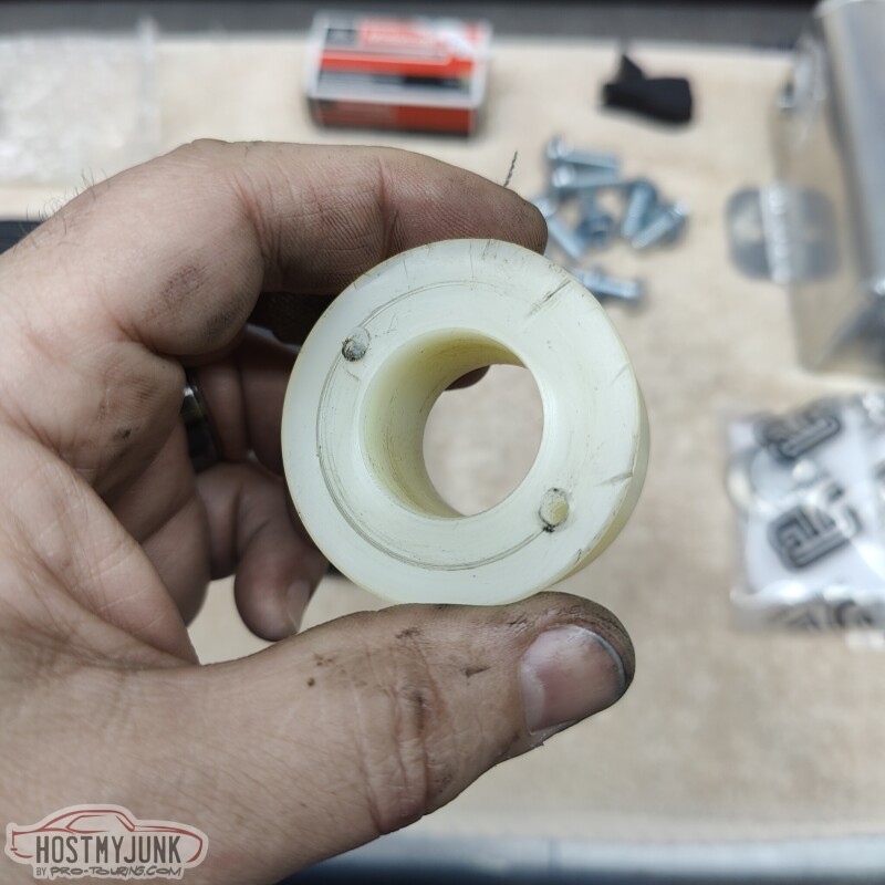
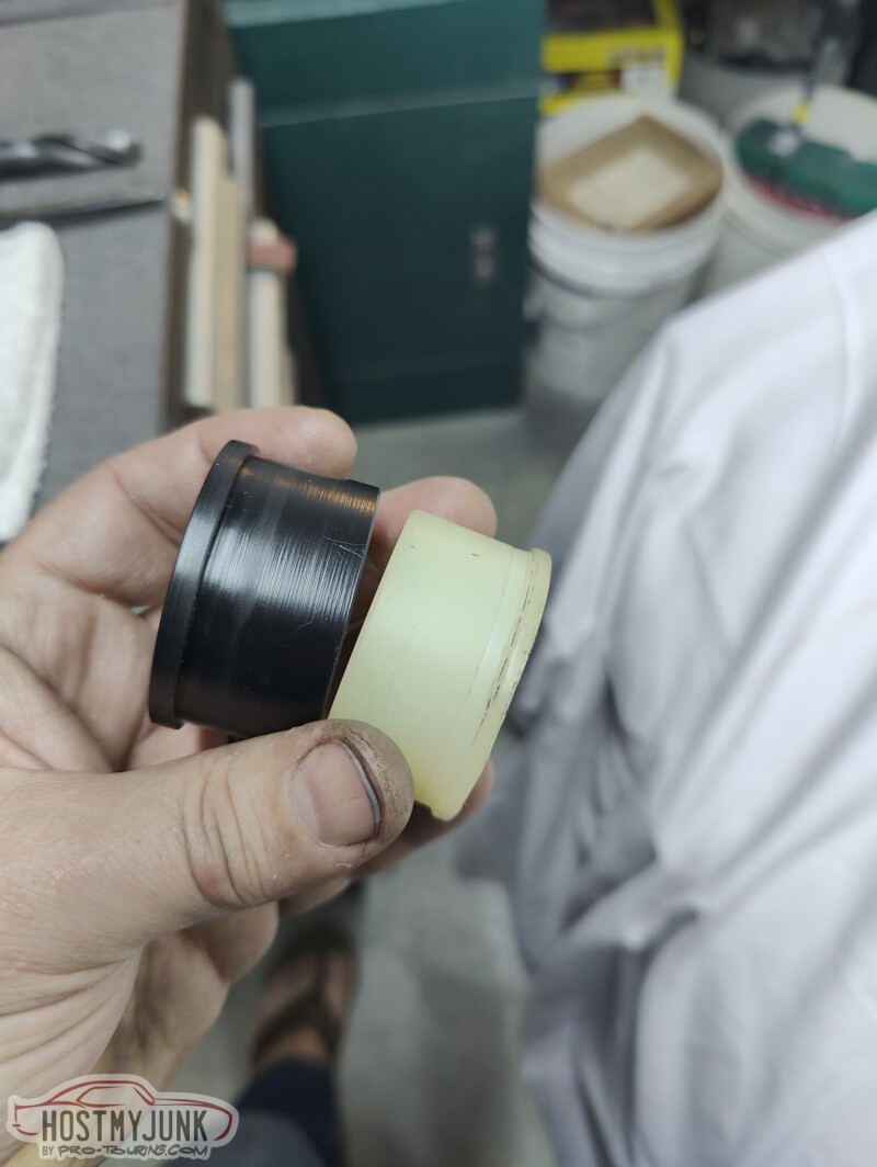
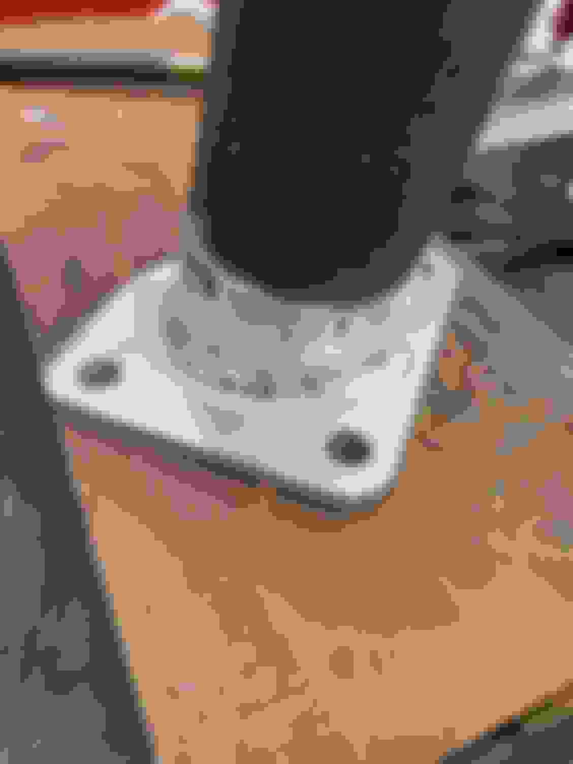
This is the bushing that supports the steering shaft inside the column. Whenever I would drive the car on a hot summer day, I would notice that the steering would get a little sticky. I suspect that this nylon bushing swell up from the heat and causes the steering to bind a little. The holes are from the screws that I installed to pull the bushing with a slide hammer.
The bushing on the left is one that Vic made on his lathe. It is made out of Delrin, which I hope will be more stable with temperature changes.
LOVE the hinges. I have Eddie Motorsport hood and trunk hinges. The best thing about them is the smooth action vs the original springs and torsion bars. My hood hinges are the same though. They don't open as far as the factory. Watch your forehead and eyes when working around it with the hood open. I actually had the body shop hold my hood and trunk lid while I finished the wiring and trunk upholstery so I didn't have to deal with limited access.
Originally Posted by Project GatTagO
Before we finalized the intake, we thought it would be good to install the new Ring Brothers hinges. These are very well made and have plenty of adjustment to get the hood lined up well.
Installing them was a simple remove and replace operation and after a bit of fiddling with the adjustment, the hood was closing better than it ever has before. We did notice that these hinges don't allow the hood to open as much as the stock hinges. I guess this was mentioned on the Ring Brothers website, but I somehow missed it. I really don't think it will cause any issues...
Happy New Year to Everyone and thanks for following along.
Today we decided to take a little break from turbo stuff and figure out how to upgrade the brakes. Over the last year or so I have been seeing electronically assisted brakes on various cars and on a couple of YouTube channels that I watch. The technology seems really cool and by all accounts they work great.
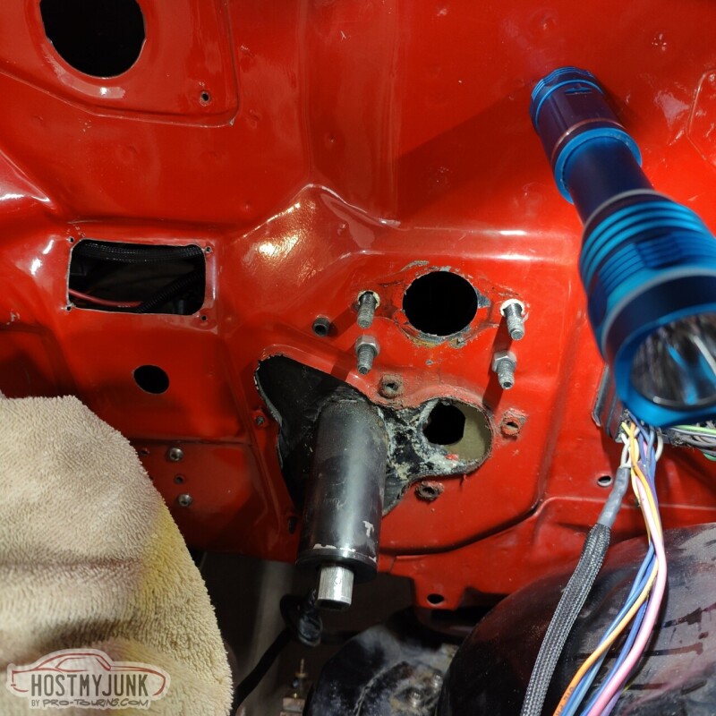
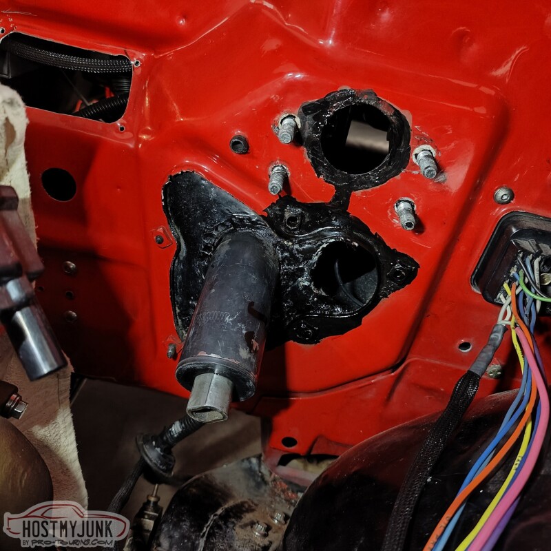
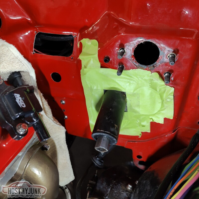
I started by removing the manual MC and the old mount for the clutch MC. There is a little rust here and there, but remember, this car was "done" 20 years ago. That area will definitely get cleaned up.
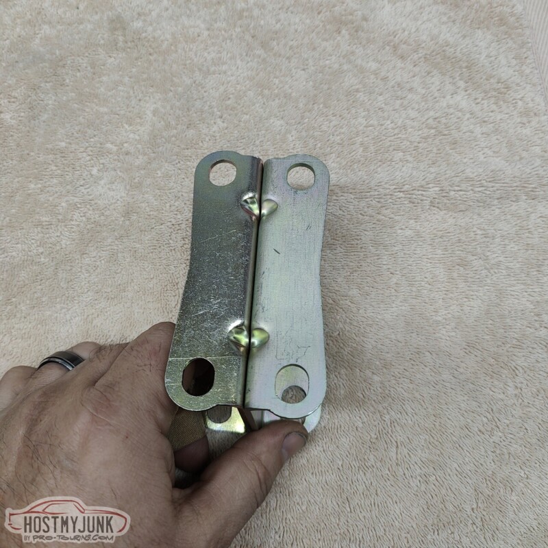
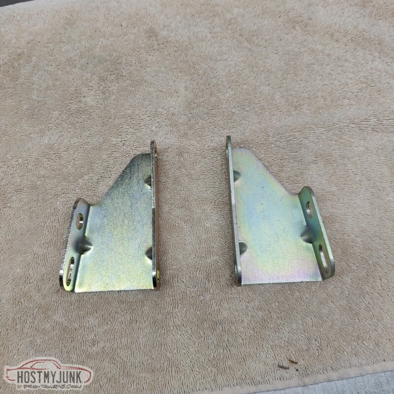
I figured a good place to start to be these brackets that I got them I was planning on doing vacuum power brakes. These are from DSE and it is their reduced angle bracket.
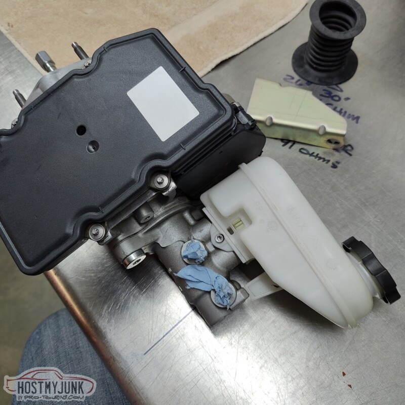
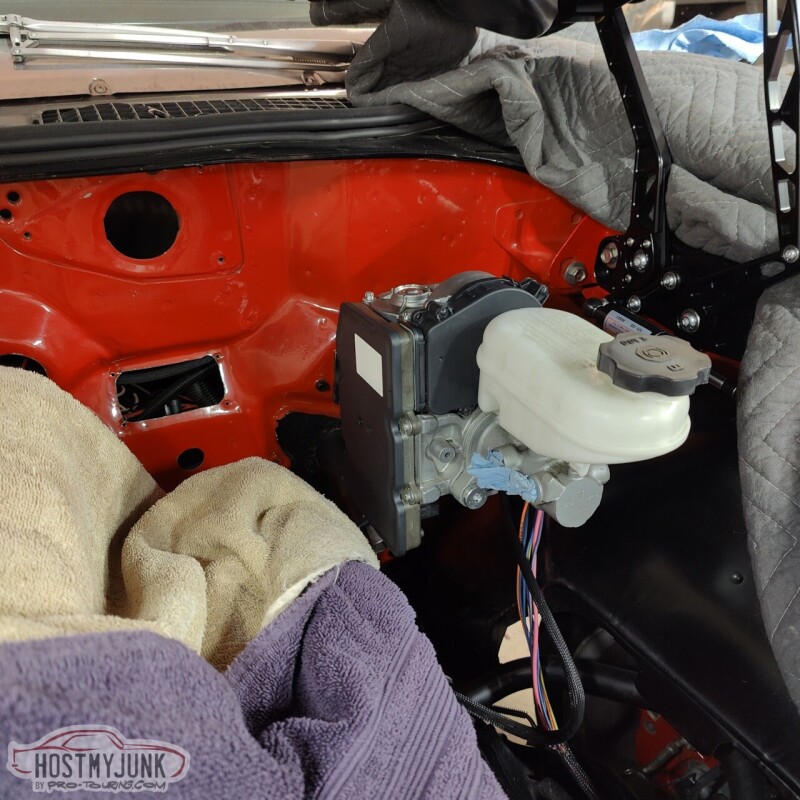
The is the Gen 1 Bosch iBooster unit that I got. It is from a 2010ish Tesla Model S with the adaptive cruise control. Bosch has a Gen 2 model of the iBooster available, but I don't like the looks of them and I am sure that none of the features of the new unit are even applicable to what we are doing here.
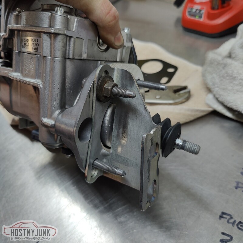
After a little welding, milling and hole sawing, we had the bracket modified to fit the iBooster.
It is bolted to the firewall here, but there is still a lot to sort out.
I am not really happy with how the pushrod alignment is looking at the moment. The unit might actually need to be tilted up at the front a little more, but I am already concerned about hood clearance. We will sort out the details the next time.
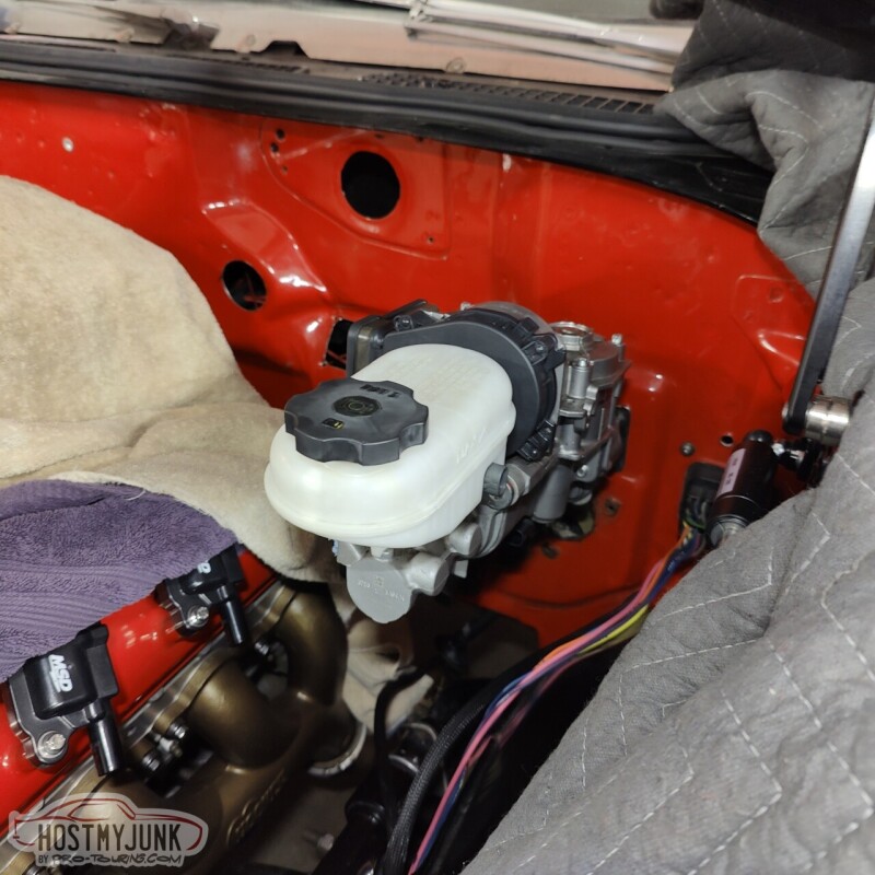
I really like the way these look. They add a little high-tech touch to the engine compartment.
im using a gen2 ibooster in my car but i havent shown anyone yet. im actually about to bleed it and power it up for the first time in the next couple days, just got the wiring finished up yesterday on it.
some of the pins were quite difficult to identify and source, so i took pictures of the labels.
wow, march, thats a lot of time to accomplish so little.
dont mind the reservoir, it gets mounted on the firewall once im done with wiring and bleeding.
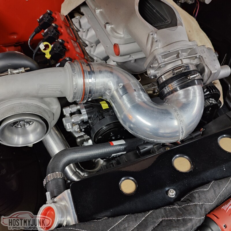
This seems like a pretty straightforward part to make, but it's quite intricate. There is very little space and we had to use a donut to get the radii tight enough to connect the dots.
There is a slight gap where the pipe meets the compressor discharge. This was done to accommodate any movement due to heat, etc...The Summit Racing clamp is made to account for this movement. All that is left is to finish a couple of welds, add the blow-off valve, which will go on the outside bend just before the throttle body, and smooth out whichever welds we can.
im using a gen2 ibooster in my car but i havent shown anyone yet. im actually about to bleed it and power it up for the first time in the next couple days, just got the wiring finished up yesterday on it.
some of the pins were quite difficult to identify and source, so i took pictures of the labels.
wow, march, thats a lot of time to accomplish so little.
.....
dont mind the reservoir, it gets mounted on the firewall once im done with wiring and bleeding.
Did you just use the lower hole on your brake pedal? It looks like you mounted the iBooster directly to the firewall, is that right?
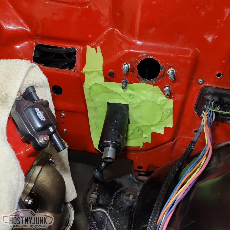
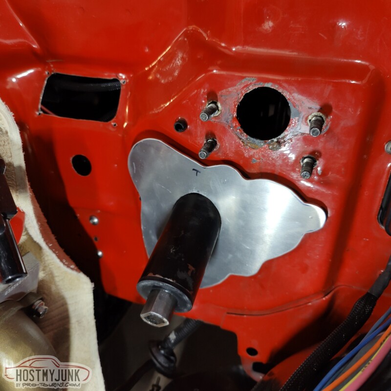
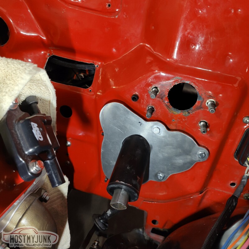
Today I had a few hours to spare, so I drove to Vic's house to make a little close-out panel that would go under the brake booster. In one of the previous pictures you can see the hole that was left after I removed the clutch MC mount. That hole needed to be covered up and I also needed to clean up some of the peeling paint and surface rust that was there.
I scraped the loose paint off and then scrubbed the surface with an abrasive pad. Then I sprayed some primer into a small cup and used a small brush to apply it and then did the same with some black paint. The point wasn't to make it look pretty, but to seal the exposed metal.
I then started to layer 2" masking tape over the whole area.
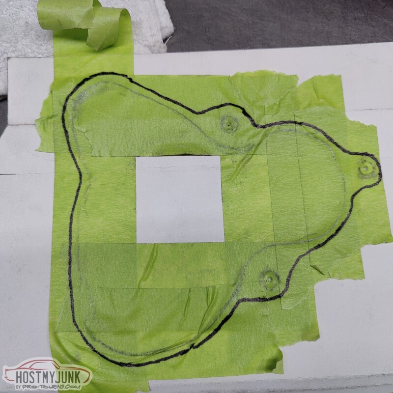
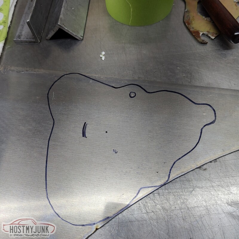
I used a pencil to trace out the outline of the patch that I wanted to cover and also marked out the 3 mounting holes.
I then transferred the masking tape template to some thin cardboard and used a sharpie to draw out the shape that would capture the mounting bolts and that would overlap the opening that I wanted to cover.
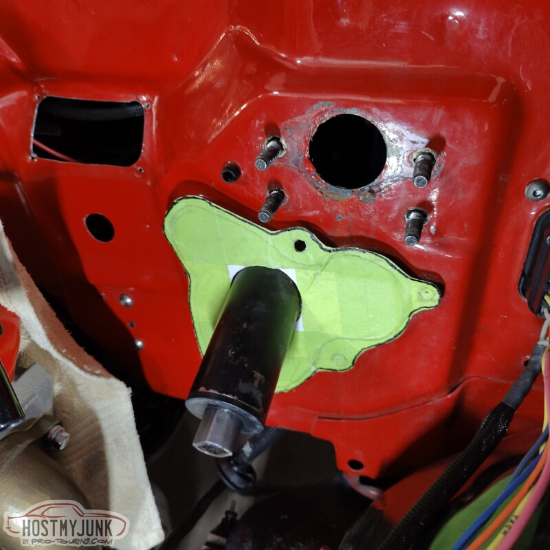
I cut the cardboard with some scissors and did a trial fit. Everything was looking pretty good.
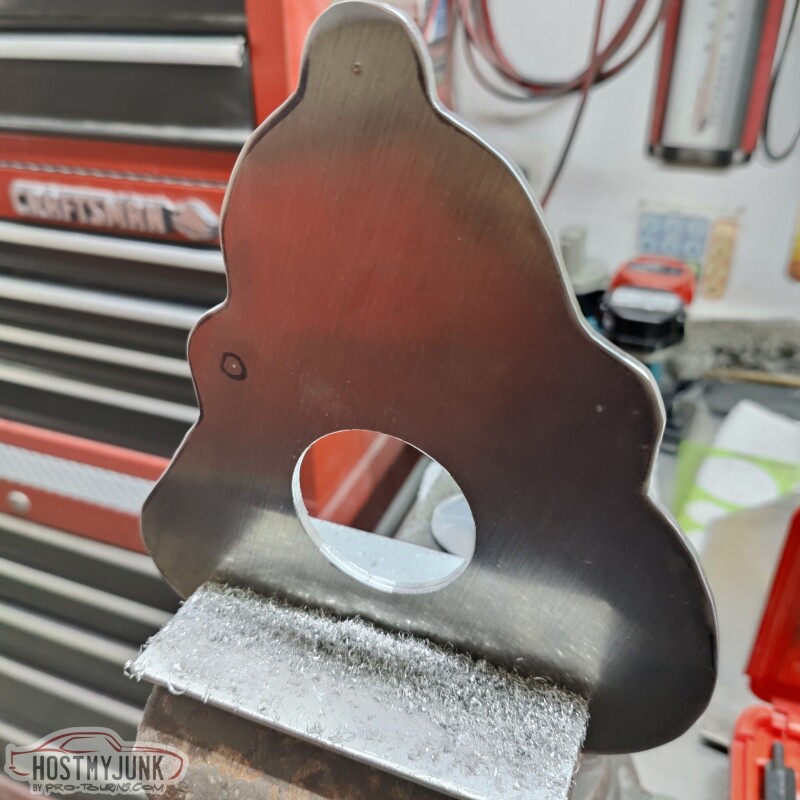
I used the cardboard template to transfer the shape and the holes to a piece of 1/8" aluminum plate.
I cut the couch shape on a bandsaw and then used a belt sander the arrive at the final shape. I also used a 2" hole saw to make the hole.
Since the column pokes through the plate at an angle, the opening had to be oval, not round, so I used a file to contour the opening until the panel fit flush against the firewall.
Then I drilled out the 3 mounting holes.
The panel fits really well. It will get painted black and I will use some window mount urethane to seal the plate against the firewall. This will keep water from collecting and keep that area clean and dry. Once the booster is installed, the panel won't really be visible, but I think it adds a finished touch to an area that looks a little raggedy before.
yeah i used the lower spot. the pushrod angle is a little higher than id like but it shouldnt really see much force if everything is working properly. i cut the pushrod off the stock booster and welded a metric nut to it at an appropriate length then threaded it onto the stock booster pushrod stud.
i made a mount out of aluminum that tilts it up and also rotates it at a weird angle to make the hardware all fit and so overall it fits and looks how i liked.
...
Nice job!
My original brake lines were 1/4" for the rear and 3/16" in the front. Any particular reason that you used 1/4" for both? I am not really sure that it even matters, but just curious.
it had to do with the fitting sizes in the honda master. both are m12 bubble which works directly with 1/4" hard lines and i wanted to avoid a stack of adapters. using the larger line there allowed me to directly connect everything up top. the only adapters are on the underside so not as visible.
also, this wilwood prop block is flippin sweet, it bolts right in place of the original one, has built in rear proportioning **** and a spot for brake pressure sensor/switch
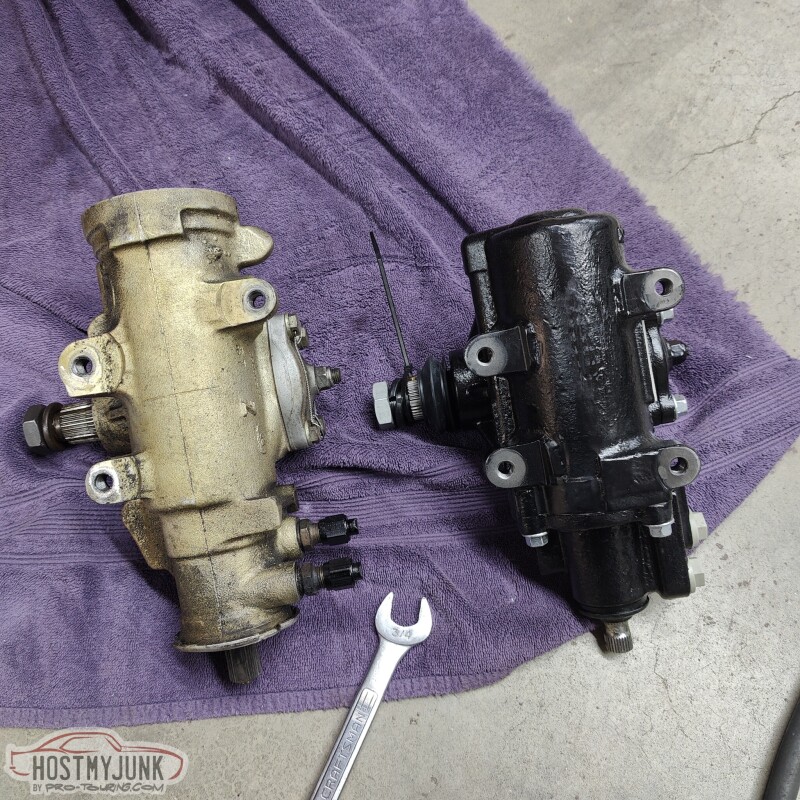
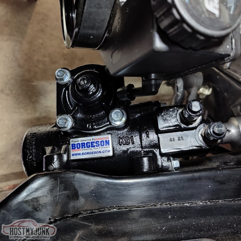
Today wasn't terribly productive. I managed to install the new Borgeson steering box. Overall it looked pretty similar to my ancient AGR steering box, with the exception of having 4 mounting ears instead of 3. My frame only has 3 mounts, so the 4th is just, there...
I was able to reuse the fittings from the old box on the new box. The Borgeson box uses metric fittings with o-rings, which were the same size as my old AGR box.
The Borgeson box also uses a slightly smaller input shaft.


 12-29-2022, 09:34 PM