When you click on links to various merchants on this site and make a purchase, this can result in this site earning a commission. Affiliate programs and affiliations include, but are not limited to, the eBay Partner Network.
With the torque arm's crossmember bolted to the welded in brackets, I measured the pinion angle.
You can see the two, large diameter shims in between the TA and the rear end housing. Each shim will change the angle about 1/2 degree. With one of those shims removed, this was my reading.
With a 2 degree reading of the engine/transmission tail down and 1.9 degree reading of the pinion pointing up, I was happy. The Maximum Motorsports instructions talk about the angles being less than 3 degrees and equal.
Yesterday afternoon, I confirmed the angles of my engine and the rear end. This time I was very meticulous to make sure that the angle finder was straight up and down for the most accurate measurements. My previous measurements were confirmed.
I think that these digital angle finders are very accurate. Maybe not Space Shuttle accurate but accurate enough for our purposes. One of the best $45 purchases I've ever made!
My measurements would vary by about .1 degree if I would remove the angle finder and put it back on. Like I said. It's plenty accurate for this work.
You need to approximate the angle of the driveshaft in order for all of your angle measurements to have a common reference point.
Andrew
Andrew, correct me if I'm wrong because often I'm wrong. My current angle measurements are 1.9 degrees. I'm just going to say 2 degrees. The pinion is pointing up and the transmission tail is pointing down. IF my car were sitting on a level surface, wouldn't my net driveshaft angle be 2 degrees from horizontal?
In the Maximum Motorsports torque arm installation instructions, there is a diagram showing this and they say to have both angles equal and less than 3 degrees.
Your engine inclination angle and pinion are both showing as sloping downward towards the rear of the car, so your component angles themselves are good at this point, but they don't tell you what your U-joint operating angles are going to be. You can have matching component angles and still have excessive U-joint working angles due to great differences in the elevation between the components. The only way to evaluate and check for that is to mock-up a drive shaft as Andrew has suggested to you so that you can factor its inclination angle into your calculations...those three component angles are measured (engine crankshaft angle, driveshaft angle and pinion angle), the U-joint working angles are calculated from those measurements. I'm assuming the 3 degree maximum angle Maximum Motorsports is conveying to you in their instructions is the U-joint working angles, not the installed angles of the components. 3 degrees of working angle is the maximum angle at which a U-joint can reliably and efficiently work at by design and it is RPM dependent...the faster you spin them, the less angle they can tolerate.
Okay. I think that I'm picturing this now! An exaggerated example would be if the tailshaft of the transmission were 24" above the ground and the diff's pinion were 10" above the ground, right? The driveshaft connecting the two would have a lot of angle.
Continuing on this line of thought; couldn't I get an idea by just measuring the heights of the trans output shaft centerline and the pinion shaft centerlines? Doing some trigonometry should solve for the angle.
What if the driveshaft's angle was excessive? How would one go about fixing that??
Last edited by dannyual777; 03-04-2021 at 12:38 PM.
This is a picture I took of the Maximum Motorsports instruction sheet for the torque arm. Looking at the picture, it didn't occur to me that the trans output and the pinion input might be on different horizontal planes.
Okay. I think that I'm picturing this now! An exaggerated example would be if the tailshaft of the transmission were 24" above the ground and the diff's pinion were 10" above the ground, right? The driveshaft connecting the two would have a lot of angle.
Continuing on this line of thought; couldn't I get an idea by just measuring the heights of the trans output shaft centerline and the pinion shaft centerlines? Doing some trigonometry should solve for the angle.
What if the driveshaft's angle was excessive? How would one go about fixing that??
Bingo, now you're getting it. From my experience with that platform I can almost guarantee you're not going to have an issue U-joint angles unless you your rear suspension is dropped by a large amount (dropping the rear suspension raises the pinion elevation relative to the crankshaft center line). You'll want to measure it to be sure and you can simulate the driveshaft for a quick look by using a piece of steel or plastic pipe jammed in between the transmission output shaft yoke and the rear pinion yoke.
Once you do that, you will measure the driveshaft angle and use subtraction to calculate the operating angle of the front U-joint (subtract the lower measurement of the two from the higher one) as long as the driveshaft angle is also sloping downward towards the rear of the car. If the driveshaft is sloping upward towards the rear of the car you would need to add the same two measurements together to calculate the U-joint operating angle. Once you have that you move to the rear U-joint and use the method to calculate the rear U-joint operating angle (using the driveshaft angle and the pinion angle this time, subtracting the lower measurement from the higher one).
If the U-joint operating angles were excessive, you could correct them a few different ways, i.e. by raising the rear suspension ride height, using a Ford 9" rear end to take advantage of its lower pinion height, or be raising the transmission tail shaft and tipping the rear pinion downward simultaneously. As you know, the last method would be very problematic for you.
Yes, Todd, you're right! There is no way I could raise the tail of the T56. It's up as high as it can go without hitting the trans tunnel.
I got under the car today and took these measurements:
22.5"
About 23.5"
A quick tape measure measurement between the transmission output shaft to the pinion flange showed about 47". I did some math and came up with a working angle of roughly 1.25 degrees.
......I'm assuming the 3 degree maximum angle Maximum Motorsports is conveying to you in their instructions is the U-joint working angles, not the installed angles of the components. 3 degrees of working angle is the maximum angle at which a U-joint can reliably and efficiently work at by design and it is RPM dependent...the faster you spin them, the less angle they can tolerate.
The picture of the MM instructions that I posted in post #246 shows the 3 degree maximum as an installed max, not a max working angle. At least that's what it looks like to me.
It's confusing because a common, old rule-of-thumb on the engine/tranny angle is "3 degrees down at back" -- and equal/opposite angle on the pinion "3 degrees up". But the "less than 3 degrees" is also often cited as the max u-joint operating angle.
It's confusing because a common, old rule-of-thumb on the engine/tranny angle is "3 degrees down at back" -- and equal/opposite angle on the pinion "3 degrees up". But the "less than 3 degrees" is also often cited as the max u-joint operating angle.
That's a great summary, Michael. It can be confusing for sure. I'll be aware of it for my next project, the resto-modification of my very first car. My 1980 Camaro Z28 that I've owned since it was pulled out of the dealer's showroom.
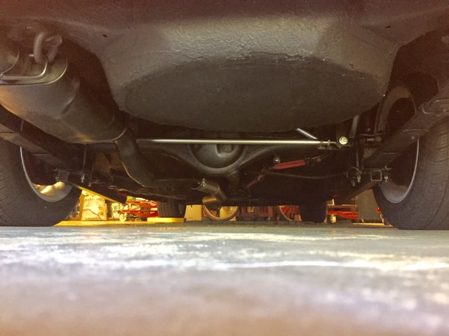
The torque arm is completely installed so I thought I'd post a couple of pictures from the rear of the car. The aftermarket suspension parts are high tech and ultra cool looking. I'm certain they'll perform to the level that they look !
I've recently removed the gas tank so these pictures really show the rear suspension.
Your last picture reminds me of the one I took of mine -- a couple of months back I finished fabricating a Panhard rod for the Toy.....was a fun project.
I want to mention that even though the major suspension work is done, there remains a lot to be done. I've still got to buy bumpsteer measuring equipment and get to work on the front suspension. That will come later this month, March 2021.
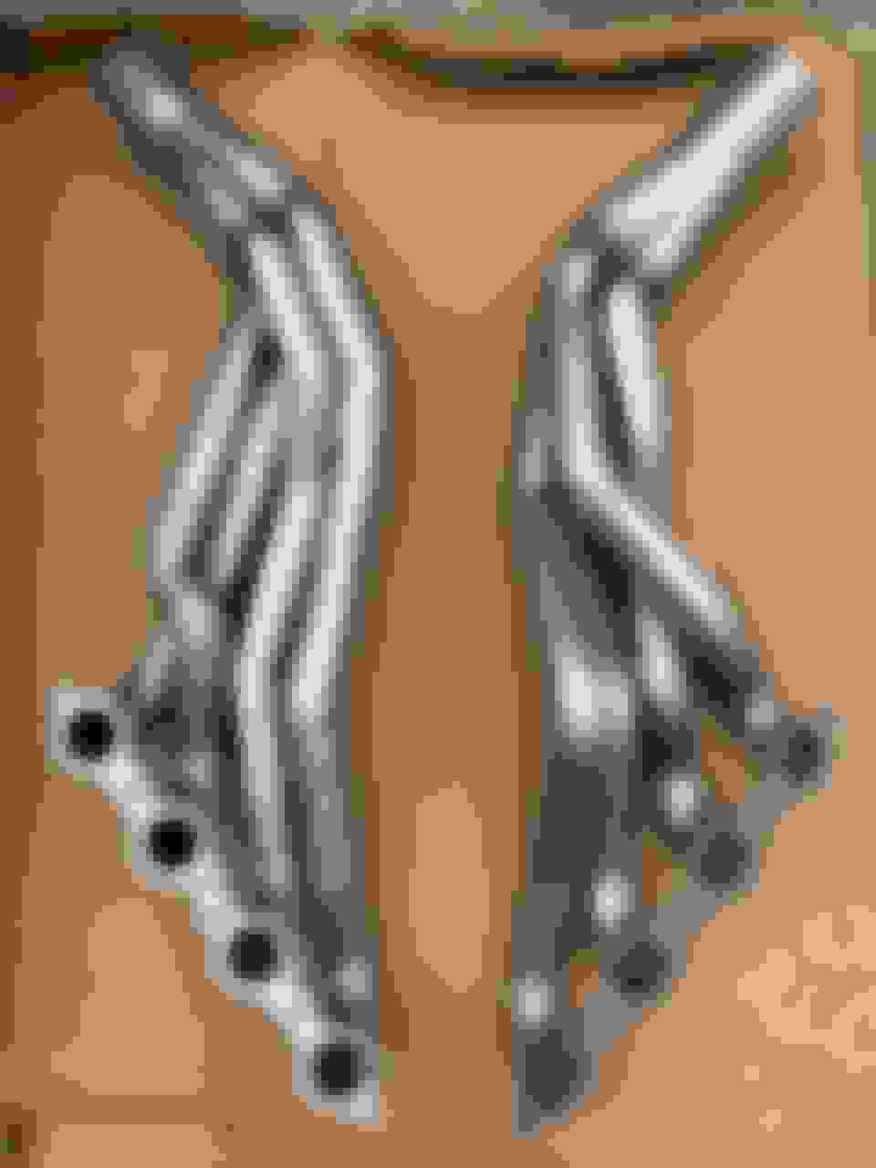
According to the installation instructions, you must remove the starter and the oil dipstick tube. My Powermaster starter is still in it's box but I did have to remove the OEM dipstick tube. The driver's side was ready to go as is. Installation of both headers was very easy with my car up on the wooden jackstands. The passenger side slid right into place but I had to work the driver's side just a little bit. I ended up removing my Maximum Motorsports hybrid steering shaft on the driver's side and the header easily slipped into place. I probably didn't need to remove the steering shaft but it was easy to do and so I did it.
Passenger side is still loose waiting for my starter to be installed.
I used the OEM exhaust manifold gaskets as the header gaskets.
The Hooker instruction say, "Place a stock (new or used) GM multi-layer steel manifold gasket between the header assembly and the cylinder head ....."
Bummer! I've got a couple of plug wire boots touching the headers. Definitely not good! These are brand new wires and I've looked at aftermarket wires. For being so short, they're pricey. On the other hand, not much on this project hasn't been .
I'm open to suggestions on the plug wires touching the headers.
Tip - check both flanges for "flat" with a machinists straight edge. Doesn't take much "unflatness" to cause all sorts of issues from a simple, but maddening exhaust leaks to stripped threads because of overtightened fasteners - trying to get them to seal. Be sure they're actually flat.
You putting them on as they are or going with coating? You're going to need a different boot.....

 03-03-2021, 07:56 AM


 !
!


 .
.

