

Madaguy 1955 Nomad Build


Thread Starter

Joined: Apr 2012
Posts: 2,171
Likes: 716
From: Ruckersville, VA
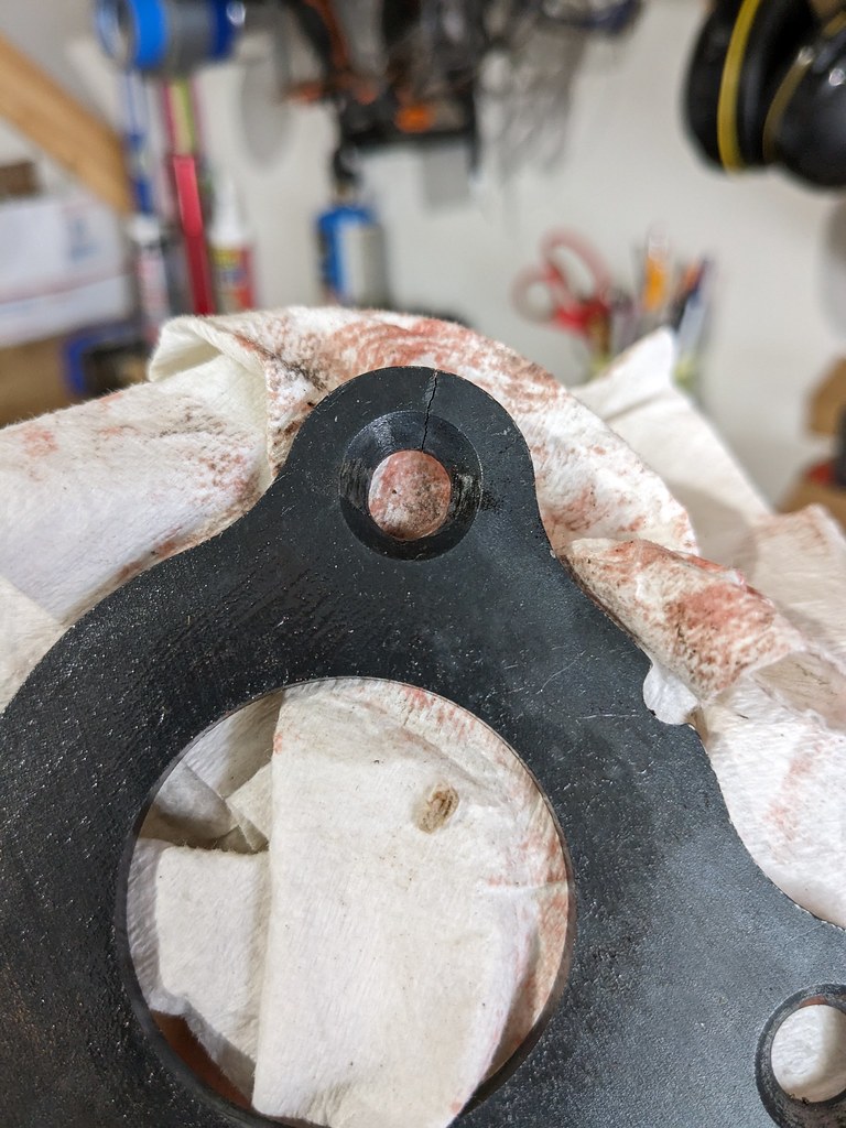
I love building cars, but wow they can really put you on a roller coaster ride of emotions! I'll get more into that in a bit, but where I left off was making sure that my cam end play was right before I moved forward with the final torque specs. I assumed that the reason for the endplay being so tight was the cam retainer plate, so I called Summit and they promptly send me a new one and had that in less than two days! Thanks @Summit! I quickly got that new one installed and took the measurements and again came up with .002" so I was quite bummed about that. So my next call (which should have been the first) was to Scoggin-Dickey who made the cam. I talked to the parts guy and asked him what they recommend for end play, and went back to talk to the guy who actually makes the cams! He came back and said that they recommend a .002-.004" of clearance on their cams, so I'm right where I need to be. What a huge relief, so thanks to both Summit and @SDPC! So I figured that since Summit had sent me a second plate that I'd just put that new one back on a box and keep it for my next build. Well glad that I had it because when I went to install the first one that I bought, I got to the bottom bolt and hear a loud snap. I'd read this happening on a few of the reviews other people posted, well the bottom of the cam plate cracked in half! So it all worked out that I had a spare. I removed and replaced with the new one and now I have a short block!
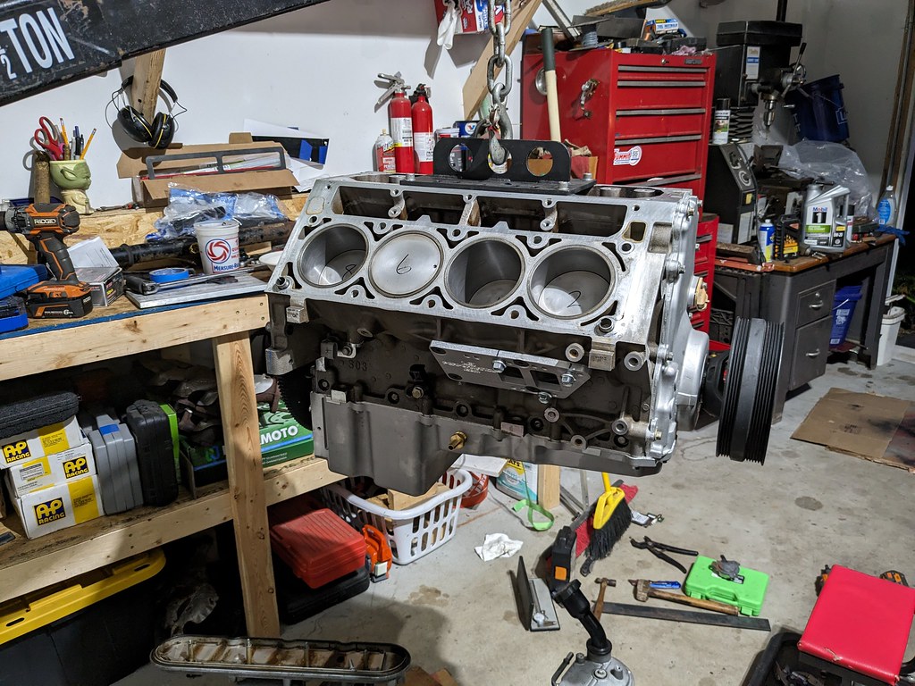
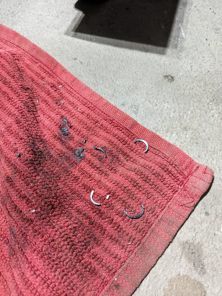
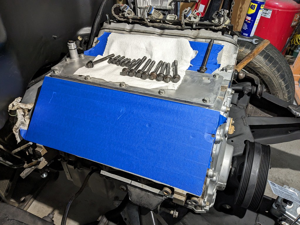
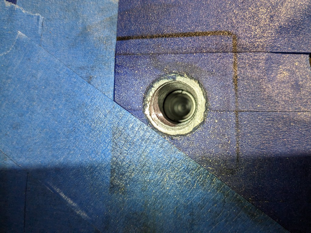
So glad that it spec'd out for me, so I quickly moved on to get my long block back together so that I could get it installed in the car. I have everything to get this engine to fire up and run, so I'm getting really excited now. I ran a thread cleaning bolt that I have in and out of all the threads to clean out the trash. Some of them had a lot of junk in them. I picked up the ARP head bolts and followed the instructions to a T, and then followed the torque spec sequences. Got the driver's side done, then moved to the passenger side. On the third pass torqueing the second to last head bolt, all of a sudden the bolt felt spongy and my heart sank. I removed the bolt and I saw some threads...
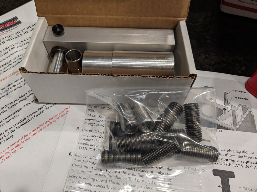
I walked out of the garage and just went to bed. I tried searching for a solution and everyone seemed to say that a threadsert was the best repair when this happens. Was not thrilled to find that the kits were about $700 bucks! I started looking around for some used kits when I stumbled on a site called Huhn Solutions with a product called NS300L. It started off as an alternative to the Time Sert repairs for Northstar engines, and they developed a kit for LS engines. I really liked everything about the kit and it had really good reviews on other sites. I really liked that the insert was much stronger looking than the Time-Sert kits. His kits for LS included enough to do all the head bolts, but I really just wanted to repair the one with pulled threads. He said that he could put together a kit with 11 inserts, and knock some money off of the total cost. His kit is about half the cost of the Time-Sert kit so I ordered it.
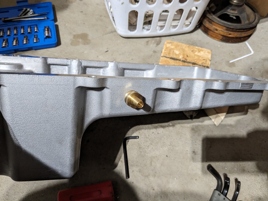
Now that I had a solution, I just continued on and got the motor/trans ready to install. Knowing that I wanted to add a turbo down the road, I drilled/tapped the oil pan for a 1/2 NPT fitting and added the only fitting I had. I taped the barb closed.

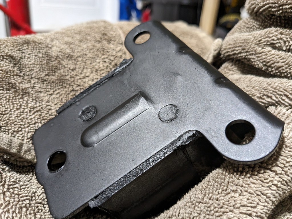
I'm sure I've seen others do the same thing, but I had to grind down the back side of the engine mount because it was not allowing the mount to sit flush with the setback plates.
The last thing that I wanted to do before I reinstalled the motor/trans is to remove the tailshaft to understand why my yoke would only go into the trans about 2". When I removed it became clear that this sleeve was stopping it. After a little research this is simply a sleeve with a seal for a van specific transmission. I can just remove this and then I'll be able to run the yoke that I have.

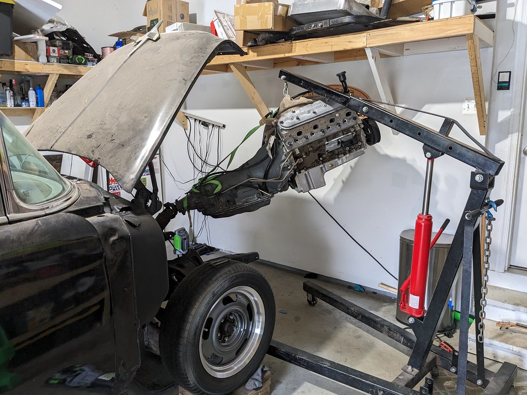
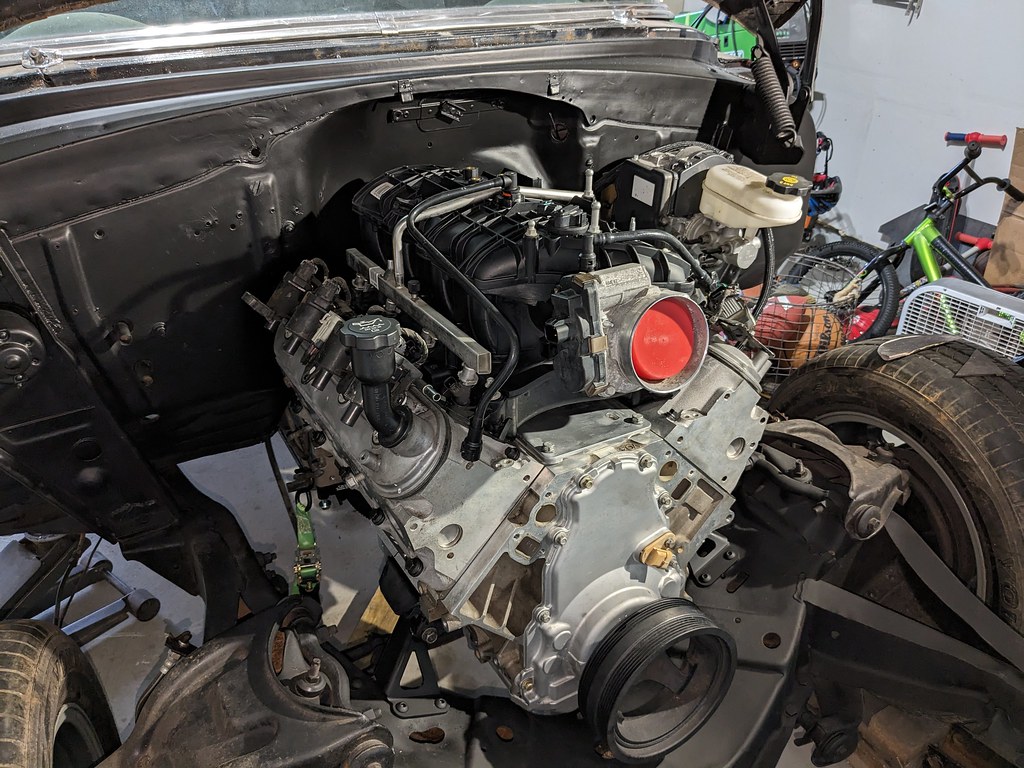
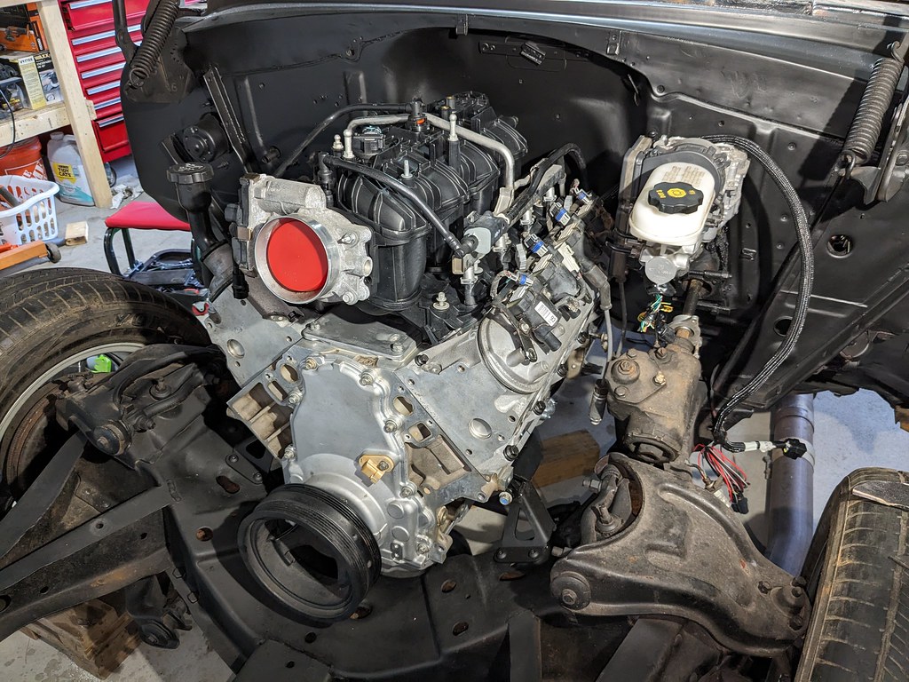
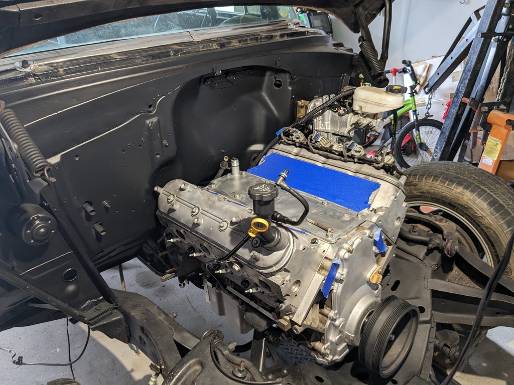
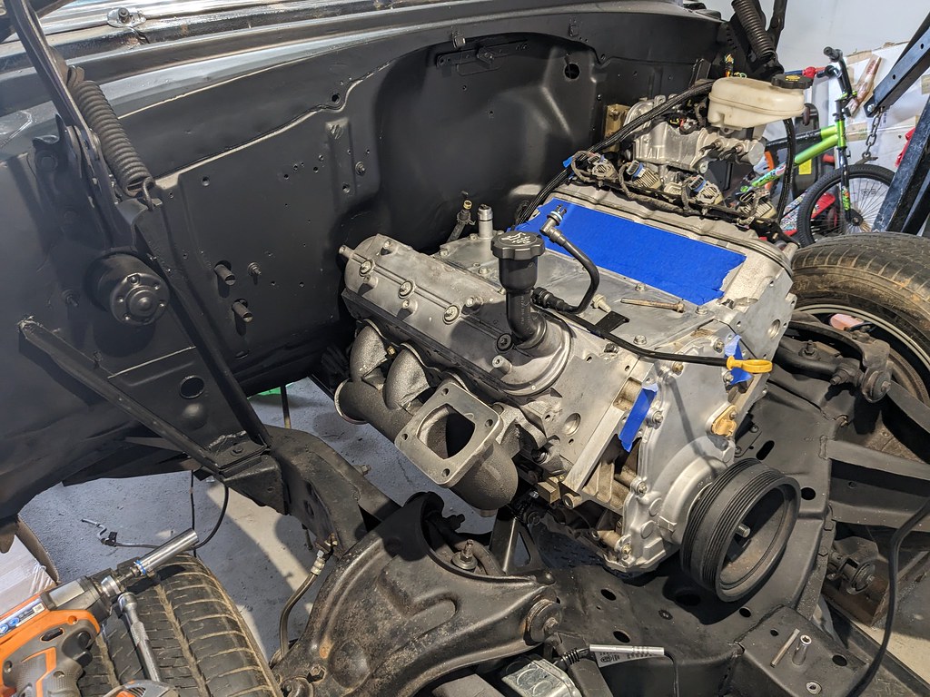
With that finalized, I bolted the engine and transmission together and got it reinstalled. It went in nice and smoothly with no damage to my new painted firewall. It fits in there really nicely, but there's still the fact that the engine is hurt and I need to get it repaired.
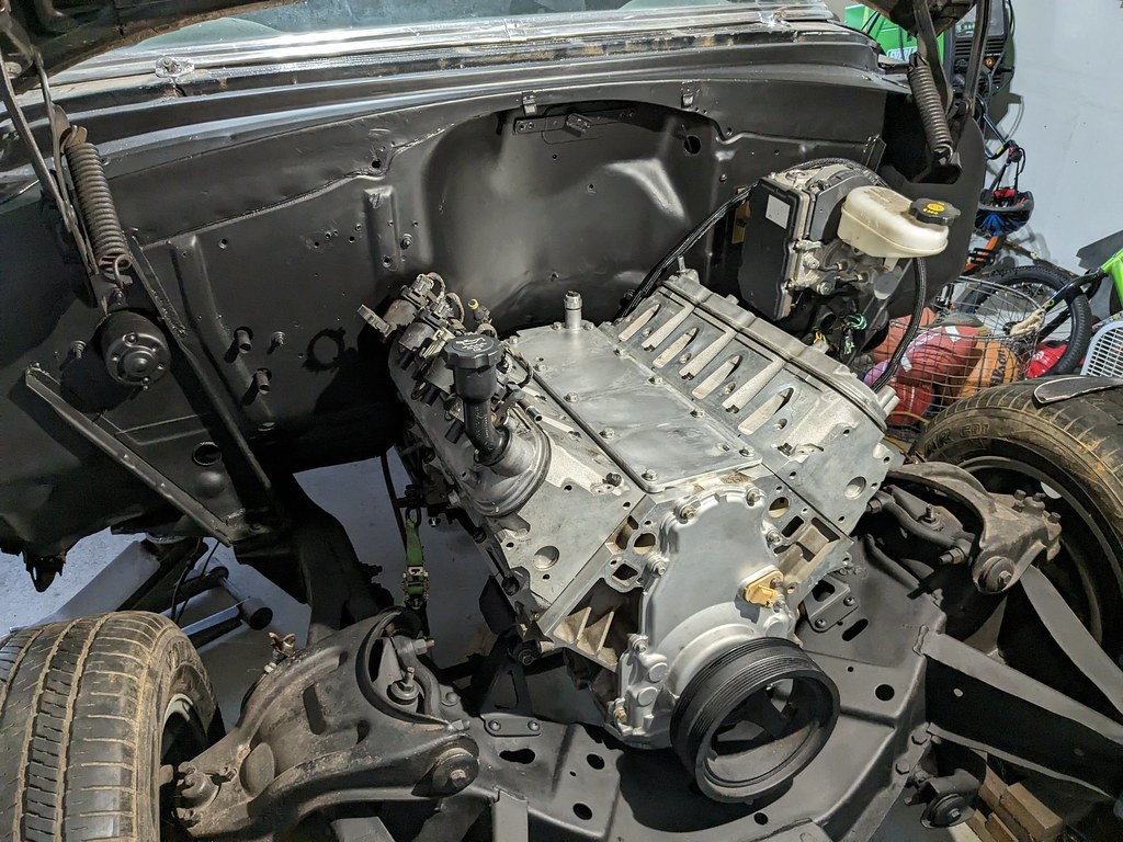
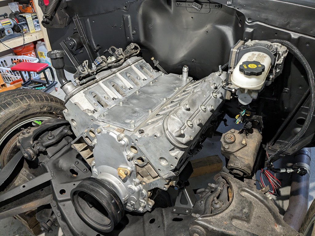
I couldn't help myself and put the intake back on just to get some motivation.
Will have another update on Part 2
So glad that it spec'd out for me, so I quickly moved on to get my long block back together so that I could get it installed in the car. I have everything to get this engine to fire up and run, so I'm getting really excited now. I ran a thread cleaning bolt that I have in and out of all the threads to clean out the trash. Some of them had a lot of junk in them. I picked up the ARP head bolts and followed the instructions to a T, and then followed the torque spec sequences. Got the driver's side done, then moved to the passenger side. On the third pass torqueing the second to last head bolt, all of a sudden the bolt felt spongy and my heart sank. I removed the bolt and I saw some threads...
I walked out of the garage and just went to bed. I tried searching for a solution and everyone seemed to say that a threadsert was the best repair when this happens. Was not thrilled to find that the kits were about $700 bucks! I started looking around for some used kits when I stumbled on a site called Huhn Solutions with a product called NS300L. It started off as an alternative to the Time Sert repairs for Northstar engines, and they developed a kit for LS engines. I really liked everything about the kit and it had really good reviews on other sites. I really liked that the insert was much stronger looking than the Time-Sert kits. His kits for LS included enough to do all the head bolts, but I really just wanted to repair the one with pulled threads. He said that he could put together a kit with 11 inserts, and knock some money off of the total cost. His kit is about half the cost of the Time-Sert kit so I ordered it.
Now that I had a solution, I just continued on and got the motor/trans ready to install. Knowing that I wanted to add a turbo down the road, I drilled/tapped the oil pan for a 1/2 NPT fitting and added the only fitting I had. I taped the barb closed.
I'm sure I've seen others do the same thing, but I had to grind down the back side of the engine mount because it was not allowing the mount to sit flush with the setback plates.
The last thing that I wanted to do before I reinstalled the motor/trans is to remove the tailshaft to understand why my yoke would only go into the trans about 2". When I removed it became clear that this sleeve was stopping it. After a little research this is simply a sleeve with a seal for a van specific transmission. I can just remove this and then I'll be able to run the yoke that I have.
With that finalized, I bolted the engine and transmission together and got it reinstalled. It went in nice and smoothly with no damage to my new painted firewall. It fits in there really nicely, but there's still the fact that the engine is hurt and I need to get it repaired.
I couldn't help myself and put the intake back on just to get some motivation.
Will have another update on Part 2
Thread Starter
Joined: Apr 2012
Posts: 2,171
Likes: 716
From: Ruckersville, VA
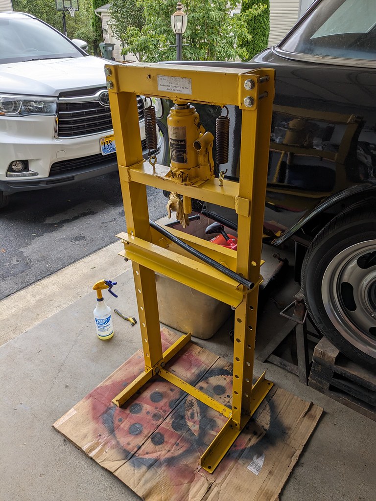
While I was waiting for the Huhn Solutions NS300L repair kit to come in, I decided to make some more progress on my iBooster swap. Just so happened that I was on FB Marketplace and saw a hydraulic press pop up. I had a sandblaster that is the same value, and thought maybe they would be interested in a trade. Turns out that they didn't want the blaster, but were interested in trading for a few 4x4 boards that I had! I love trading for random stuff haha. Came home with this little 12 ton unit, but it should do everything I need. I decided to try and bend the brackets I have to work with the iBooster bolt pattern. Worked perfectly!
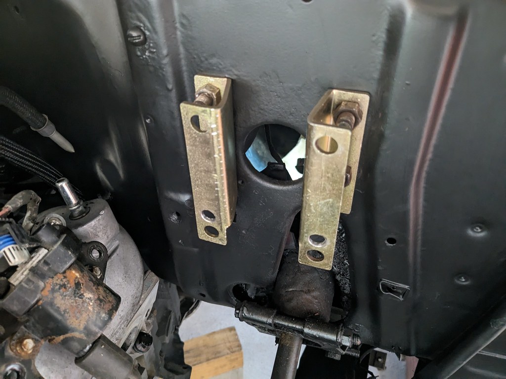
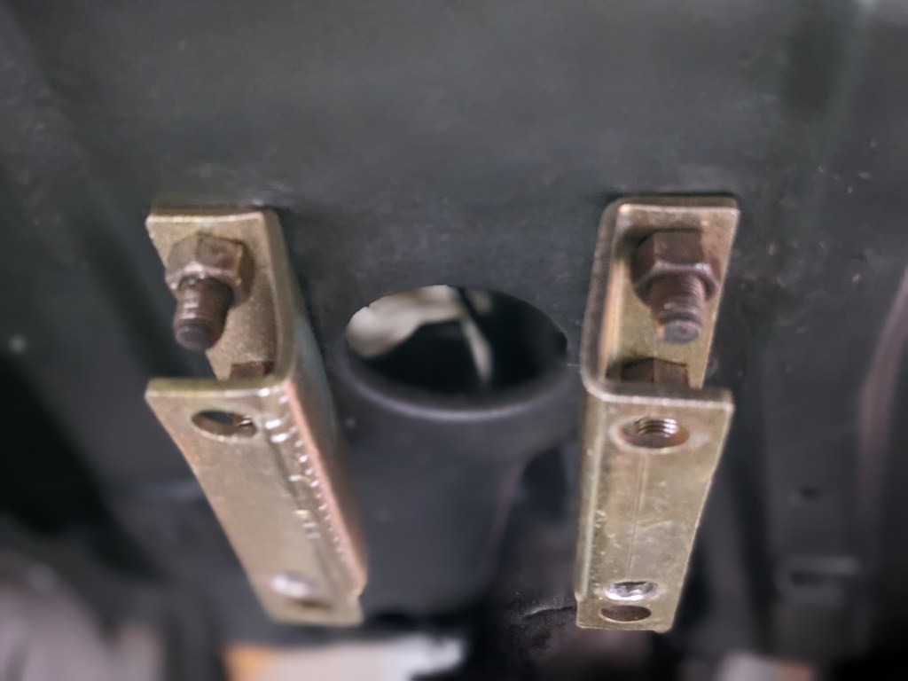
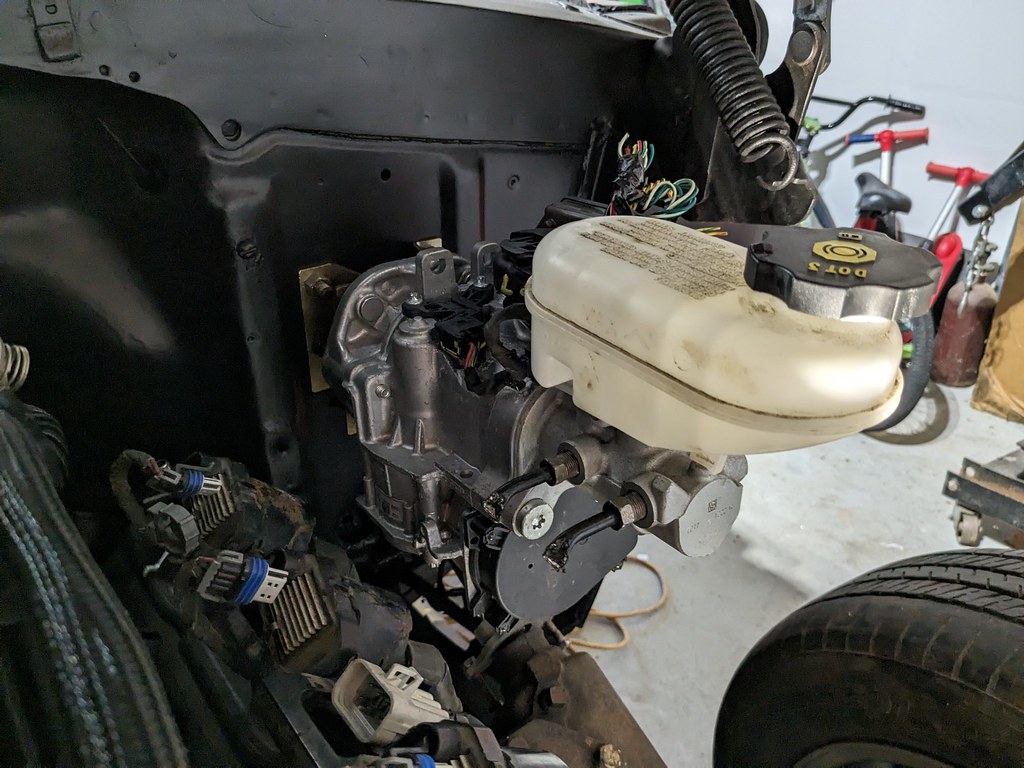
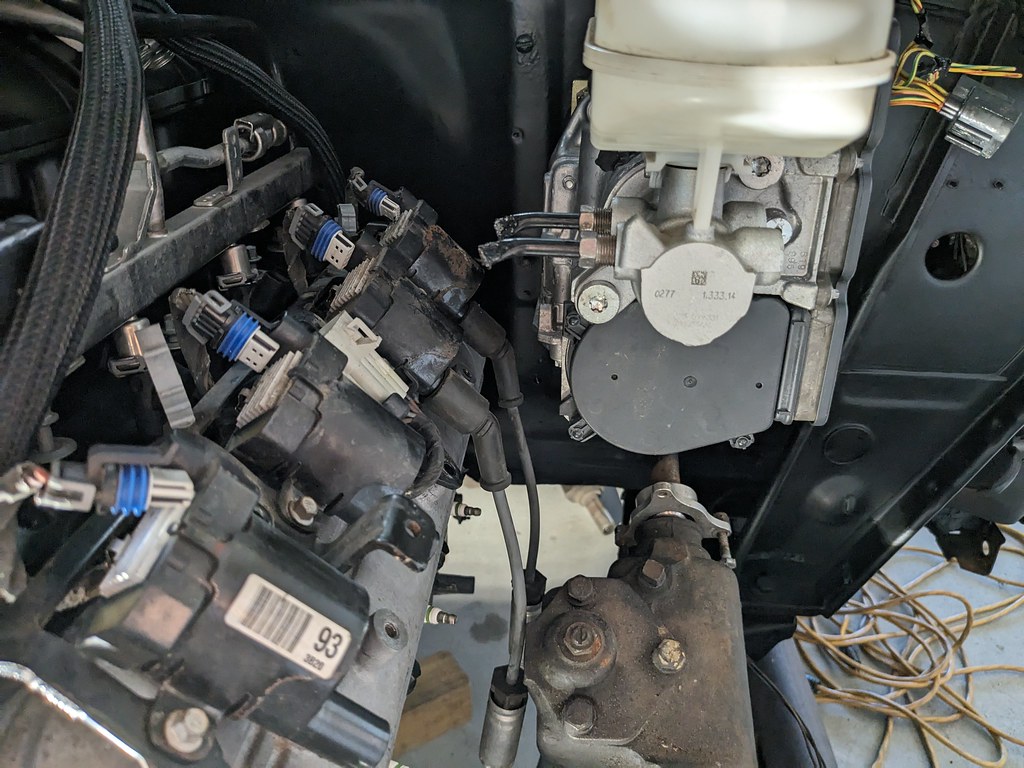
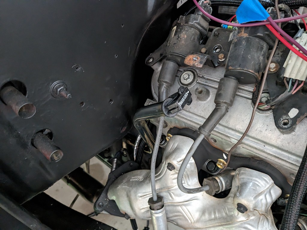
Once I got the engine back in and the brackets modified and in the right spot, I tried to install the coils. Unfortunately, the one plug wire was up against the iBooster. Luckily the bolt pattern on the booster is symmetrical, so I was able to flip it and gain the clearance. I sort of like this orientation better since it sort of looks like an experimental booster from the 50s haha. I have it mocked up right now with some nuts that are tilting it up a few degrees, so I still may need to go in and cut the bracket and weld to get the angle I'm happy with.
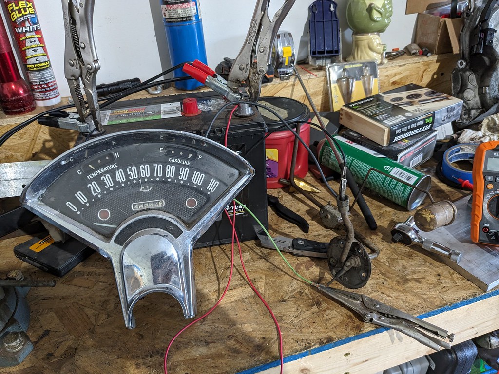
I also was thinking about my fuel tank and getting that finalized. I was thinking that I'd need to get a new fuel sender, but thought I'd try the one that came with the tank I picked up. After some trial and error with testing the sender, I was able to get the wiring right and was able to bench test with my cluster. Works perfectly in the stock location, I just had to bend it about 20* to avoid the fuel pump assembly and tweak the float lever.
Empty:
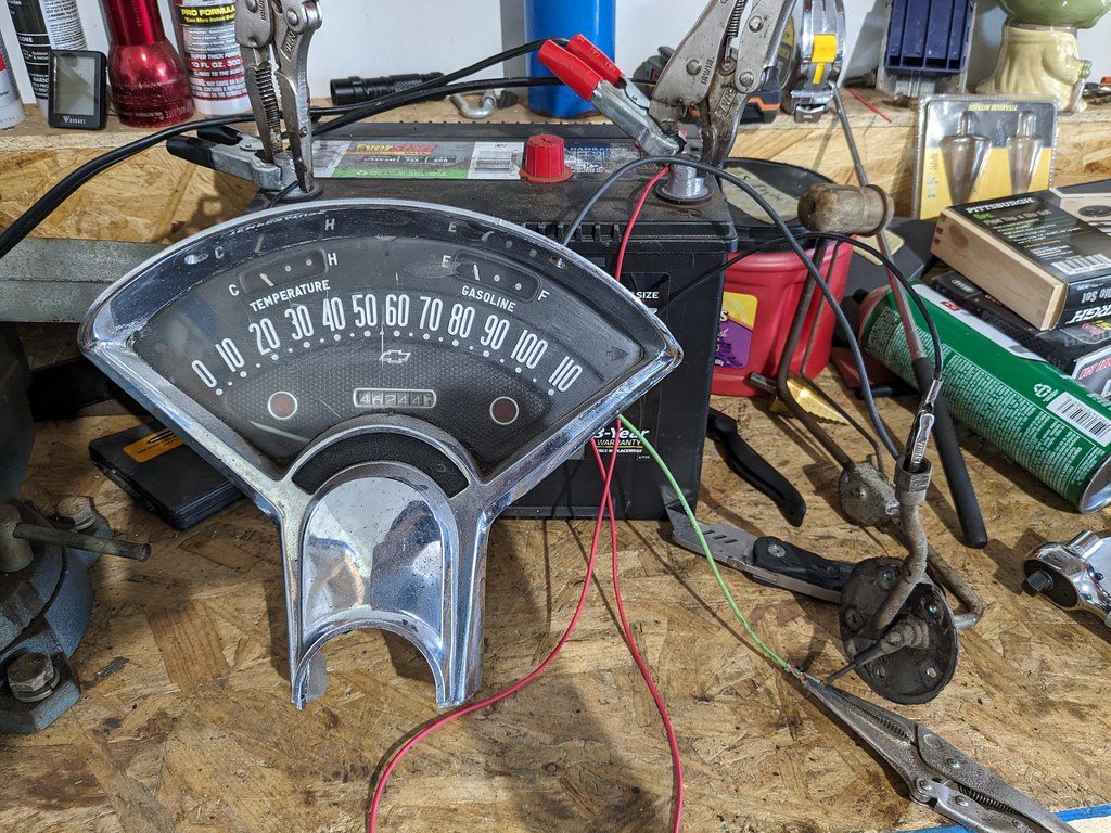
Half:
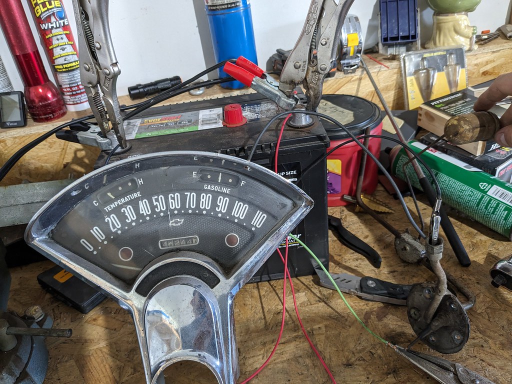
Full:
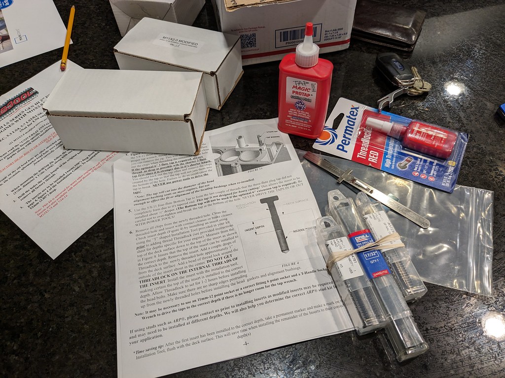
The guy from Huhn Solutions was great and he was able to get the repair kit right out to me. I ordered Friday about 5pm and it was at my door Monday afternoon! Very good news for me. The kit was very well packaged and came with excellent instructions with specific step by step for LS motors.
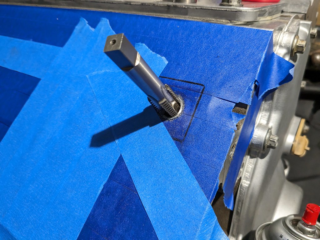
Before I started, I made sure to tape up every part of the exposed engine because chips will get everywhere.
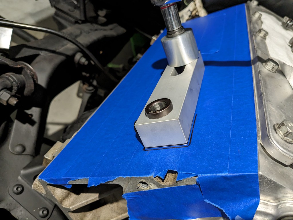
First step was getting the alignment jig set up to drill the block. This was definitely the most scary part of the hole deal, but it was necessary if I wanted to get the bolt hole repaired. The jig comes with interchangeable spacers that are used in various steps of the process. This spacer is used to center the jig over the hole with an alignment pin, and also works to hold the drill bit at the perfect angle for a straight hole. I added a little sharpie mark around the jig to monitor if it moved at all.

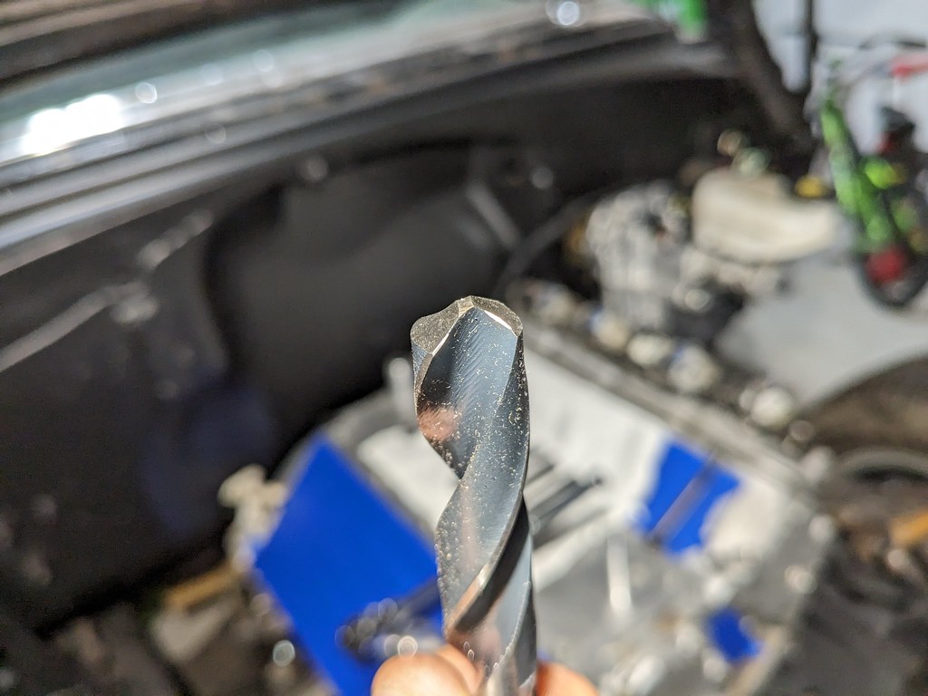
The drill bit is modified to a neutral tip to avoid drilling the hole deeper than the factory hole. this also ensure that all of the factory threads are removed.
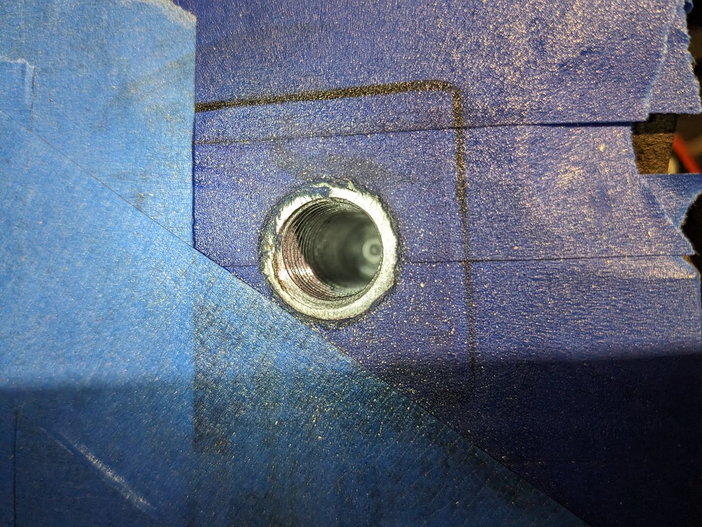
Once the hole was drilled out to the bottom, removed all of the chips. Then I removed the drill bit spacer for the spacer meant for the tap. This again provides a perfectly straight shot for the tap to ensure a nice straight cut. The kit also comes with two taps, one is a 3 flute made for the heavy cutting and a 4 flute that's more of a clean up tap and also cuts about 1/4" more threads.

Once the tap got deep enough, I was able to remove the jig.
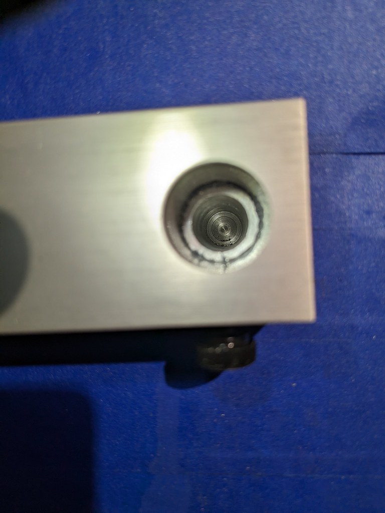
Next up was a test fit of the insert. There is a provided "T" handle that fits into the little notches on the top of the threads that allows you to get it installed to the right depth. There is also a provided depth gauge with the correct specs for LS motors.
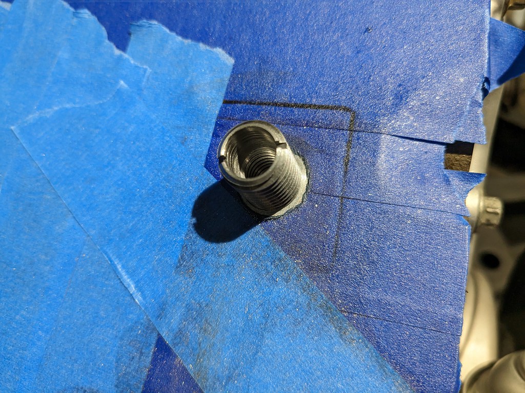
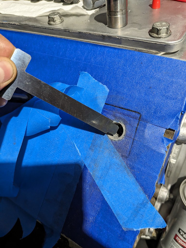
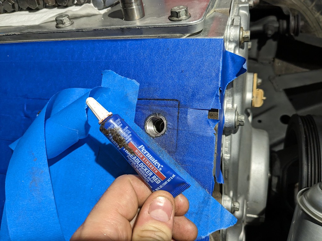
Once I threaded the insert into the new hole, I set it to the right height, and then compared it to the measurements of the untouched holes and it was spot on. It was then time to remove the insert and make it permanent. I used some red thread locker and remeasured to ensure that it was at the same location as the test fit. After that the repair was complete and I had to wait for the thread locker to fully cure 1-2 hours.
There really isn't anything for me to take a picture of, but I again went out last night and cleaned up all the threads in the block with my clean out bolt. Cleaned everything back up to reinstall the cylinder heads. I had also read a trick from Motortrend I believe that said to lightly sand the bottom of the washer that mates to the machined surface of the cylinder head. One of the issues that LS motors can have is that the machined surface of the washers and cylinder heads can actually spin while torqueing and can cause inaccurate measurements. So I tried that this time around and payed extra close attention to not having one bit of the ARP grease touch the machined surface of the head. I made it through all three stages of the torque specs with no issues! I was stoked that it was a perfect repair. Now I can focus on starting the wiring and fuel systems so that I can hear this beast come to life!
Cheers,
Ryan
Once I got the engine back in and the brackets modified and in the right spot, I tried to install the coils. Unfortunately, the one plug wire was up against the iBooster. Luckily the bolt pattern on the booster is symmetrical, so I was able to flip it and gain the clearance. I sort of like this orientation better since it sort of looks like an experimental booster from the 50s haha. I have it mocked up right now with some nuts that are tilting it up a few degrees, so I still may need to go in and cut the bracket and weld to get the angle I'm happy with.
I also was thinking about my fuel tank and getting that finalized. I was thinking that I'd need to get a new fuel sender, but thought I'd try the one that came with the tank I picked up. After some trial and error with testing the sender, I was able to get the wiring right and was able to bench test with my cluster. Works perfectly in the stock location, I just had to bend it about 20* to avoid the fuel pump assembly and tweak the float lever.
Empty:
Half:
Full:
The guy from Huhn Solutions was great and he was able to get the repair kit right out to me. I ordered Friday about 5pm and it was at my door Monday afternoon! Very good news for me. The kit was very well packaged and came with excellent instructions with specific step by step for LS motors.
Before I started, I made sure to tape up every part of the exposed engine because chips will get everywhere.
First step was getting the alignment jig set up to drill the block. This was definitely the most scary part of the hole deal, but it was necessary if I wanted to get the bolt hole repaired. The jig comes with interchangeable spacers that are used in various steps of the process. This spacer is used to center the jig over the hole with an alignment pin, and also works to hold the drill bit at the perfect angle for a straight hole. I added a little sharpie mark around the jig to monitor if it moved at all.
The drill bit is modified to a neutral tip to avoid drilling the hole deeper than the factory hole. this also ensure that all of the factory threads are removed.
Once the hole was drilled out to the bottom, removed all of the chips. Then I removed the drill bit spacer for the spacer meant for the tap. This again provides a perfectly straight shot for the tap to ensure a nice straight cut. The kit also comes with two taps, one is a 3 flute made for the heavy cutting and a 4 flute that's more of a clean up tap and also cuts about 1/4" more threads.
Once the tap got deep enough, I was able to remove the jig.
Next up was a test fit of the insert. There is a provided "T" handle that fits into the little notches on the top of the threads that allows you to get it installed to the right depth. There is also a provided depth gauge with the correct specs for LS motors.
Once I threaded the insert into the new hole, I set it to the right height, and then compared it to the measurements of the untouched holes and it was spot on. It was then time to remove the insert and make it permanent. I used some red thread locker and remeasured to ensure that it was at the same location as the test fit. After that the repair was complete and I had to wait for the thread locker to fully cure 1-2 hours.
There really isn't anything for me to take a picture of, but I again went out last night and cleaned up all the threads in the block with my clean out bolt. Cleaned everything back up to reinstall the cylinder heads. I had also read a trick from Motortrend I believe that said to lightly sand the bottom of the washer that mates to the machined surface of the cylinder head. One of the issues that LS motors can have is that the machined surface of the washers and cylinder heads can actually spin while torqueing and can cause inaccurate measurements. So I tried that this time around and payed extra close attention to not having one bit of the ARP grease touch the machined surface of the head. I made it through all three stages of the torque specs with no issues! I was stoked that it was a perfect repair. Now I can focus on starting the wiring and fuel systems so that I can hear this beast come to life!
Cheers,
Ryan
Thread Starter
Joined: Apr 2012
Posts: 2,171
Likes: 716
From: Ruckersville, VA
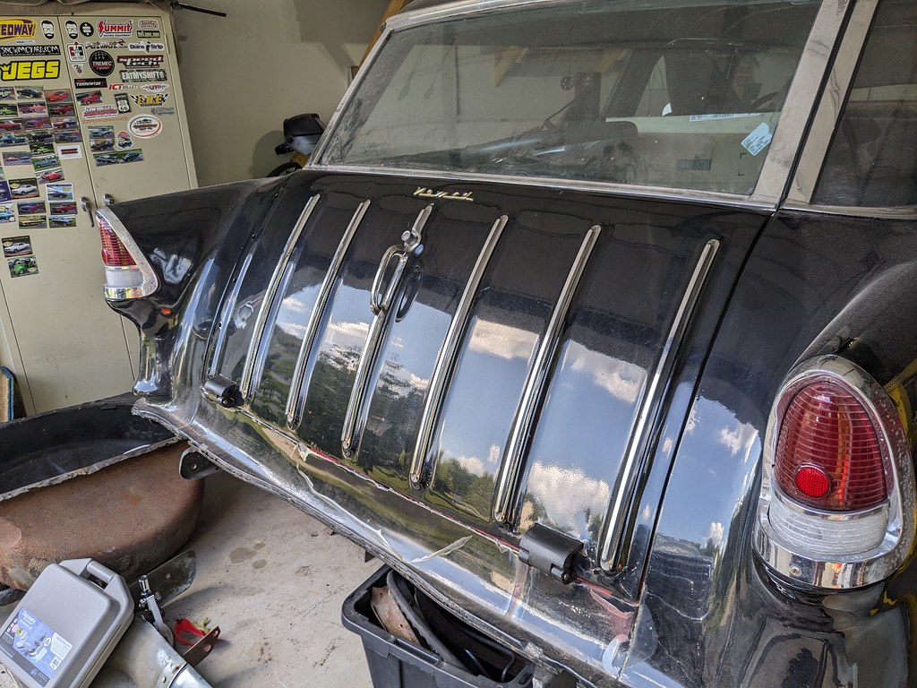
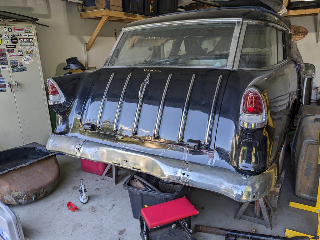
Mostly a parts update, but I'm very happy with some of the key pieces that I picked up. My family and I went back to NY to visit family and as I usually do, I was checking out a new area for parts. I found a guy selling a wagon rear bumper, and after talking to him a bit he ended up having 5 Nomads! He wasn't selling a lot of parts because he was in the process of restoring a 55 and 56 currently, but he was willing to sell me some decent tailgate bars and a rear bumper. The bumper isn't in the best shape, but it came with brackets and will look way better than no bumper at all.


Then after a little elbow grease, they look pretty darn good! I bought all 7 pieces from him, but the 7th tailgate bar was in significantly worse condition and decided to wait for one in better shape to come along.
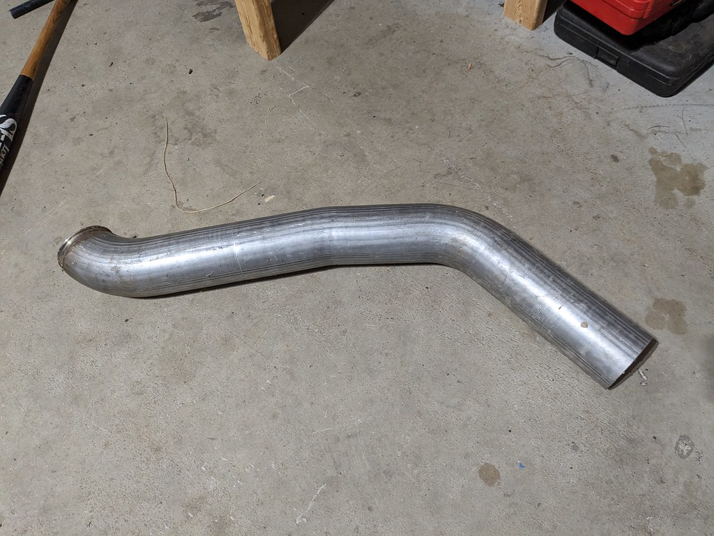
So because the plan in the next year or so is to swap on a turbo, I am trying to plan ahead. I've been keeping my eyes out for some 4" sections of exhaust to build my exhaust. I found a guy selling a 4" downpipe from a 94-02 Cummins with the HX40 for really cheap.
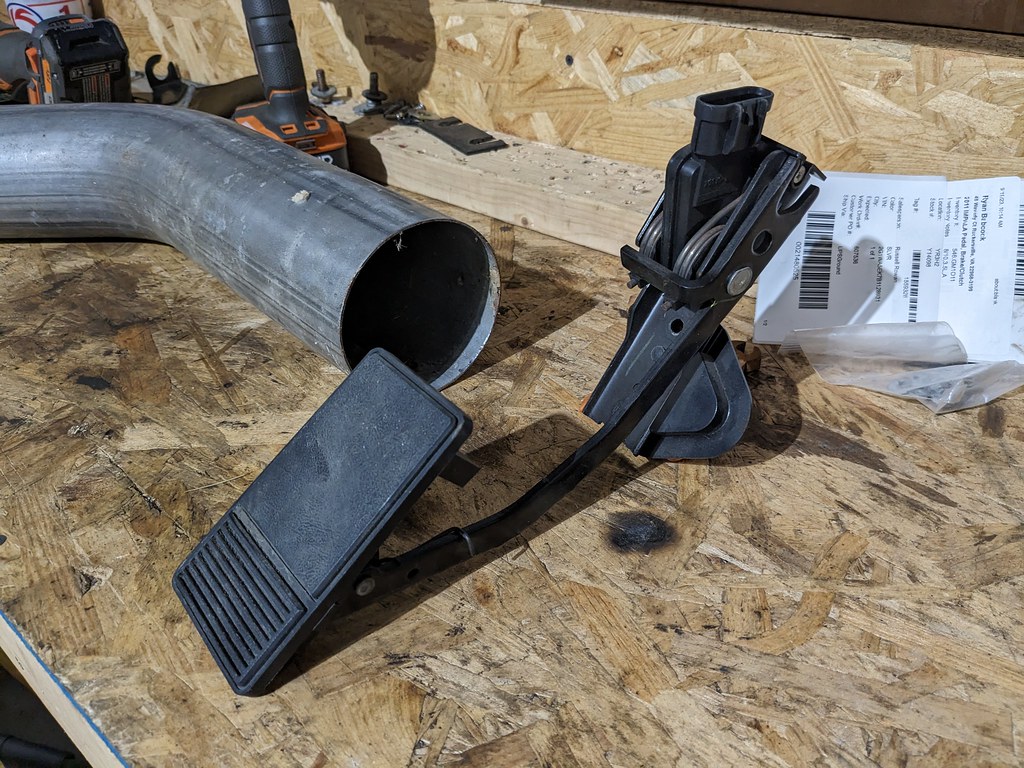
I also picked up a 2011 Impala gas pedal for my Terminator X Max since I'll be running DBW this time. It mounts nice and flat against the firewall, so it should be very easy to make a mount for it.
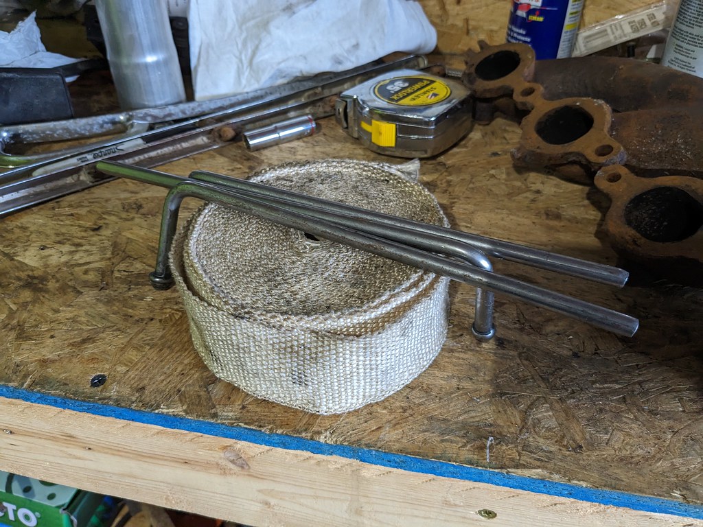
I thought this was a pretty cool full circle moment. I've been building cars for a while and have hung onto parts thinking that I'll use them sometime down the road. Well the day has come that I'll be finally using these exhaust hanger mounts and heat wrap! I bought these sometime around 2009 when I was building my 1976 Trans Am. Pretty cool that I'll be able to use these in my current project.
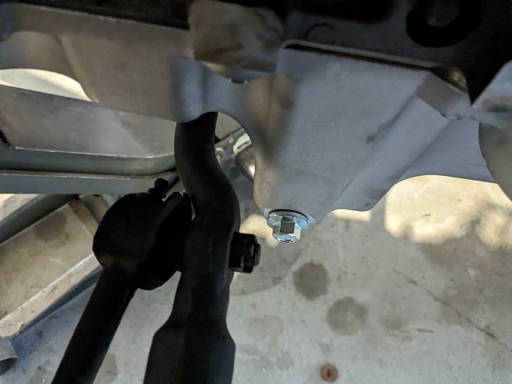
Lastly, I was finally able to get the engine back in the car and able to check on the tie rod clearance. Thankfully the car gods were on my side and there is plenty of clearance against the oil pan on both sides lock to lock. That's a huge relief since I wasn't 100% sure.

I'm hoping that over the next few days the rest of my parts come in so that I can complete my exhaust. I'm going to start laying out the wiring and get the car ready to fire up. I can't wait to hear this car come to life!
Cheers,
Ryan
Then after a little elbow grease, they look pretty darn good! I bought all 7 pieces from him, but the 7th tailgate bar was in significantly worse condition and decided to wait for one in better shape to come along.
So because the plan in the next year or so is to swap on a turbo, I am trying to plan ahead. I've been keeping my eyes out for some 4" sections of exhaust to build my exhaust. I found a guy selling a 4" downpipe from a 94-02 Cummins with the HX40 for really cheap.
I also picked up a 2011 Impala gas pedal for my Terminator X Max since I'll be running DBW this time. It mounts nice and flat against the firewall, so it should be very easy to make a mount for it.
I thought this was a pretty cool full circle moment. I've been building cars for a while and have hung onto parts thinking that I'll use them sometime down the road. Well the day has come that I'll be finally using these exhaust hanger mounts and heat wrap! I bought these sometime around 2009 when I was building my 1976 Trans Am. Pretty cool that I'll be able to use these in my current project.
Lastly, I was finally able to get the engine back in the car and able to check on the tie rod clearance. Thankfully the car gods were on my side and there is plenty of clearance against the oil pan on both sides lock to lock. That's a huge relief since I wasn't 100% sure.
I'm hoping that over the next few days the rest of my parts come in so that I can complete my exhaust. I'm going to start laying out the wiring and get the car ready to fire up. I can't wait to hear this car come to life!
Cheers,
Ryan
Thread Starter
Joined: Apr 2012
Posts: 2,171
Likes: 716
From: Ruckersville, VA
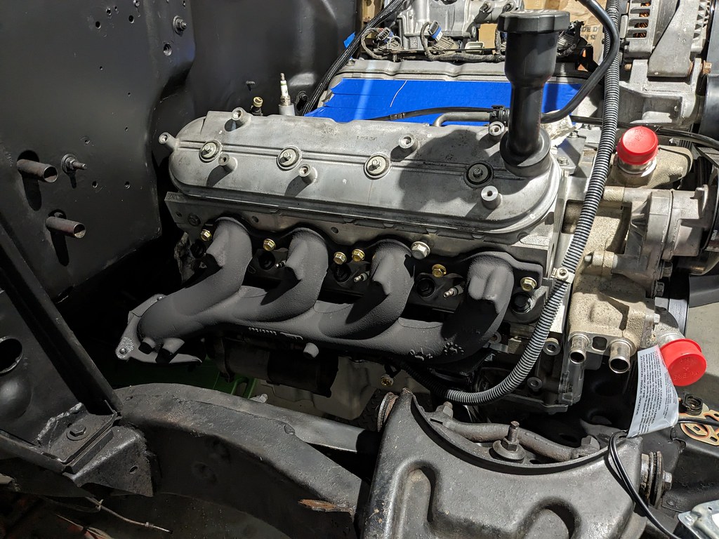
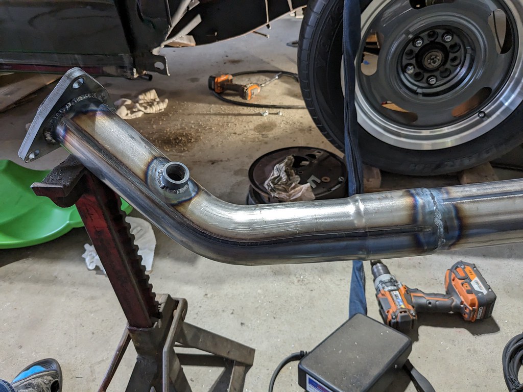
My exhaust parts all came in and now I'm ready to get started on building the exhaust. First step was stepping back and looking at the freshly torqued long block. 
Next was installing the balancer bolt. This thing had to be torqued to 235 lb ft! Marked it to have a quick reference in the unlikely event it loosened.

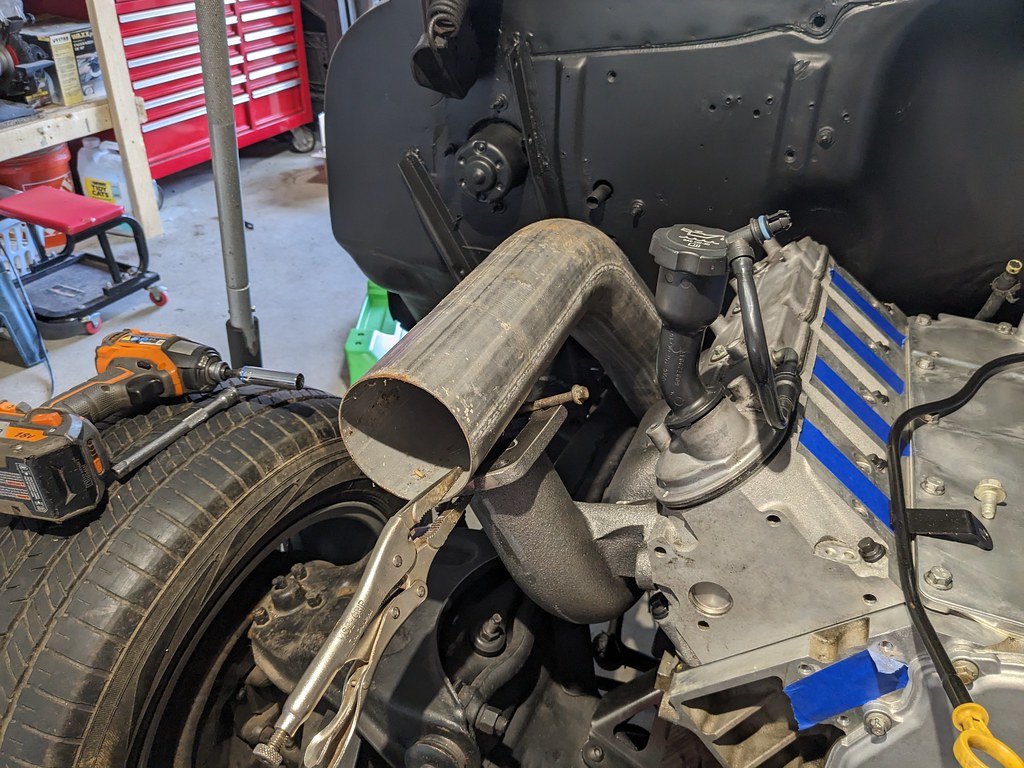
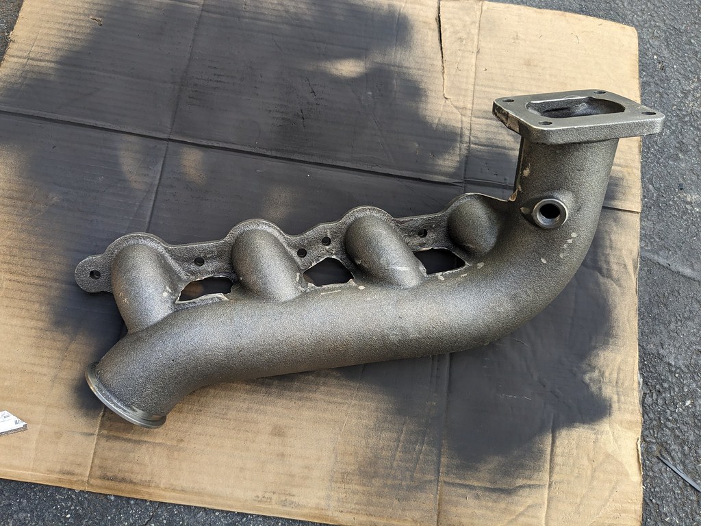
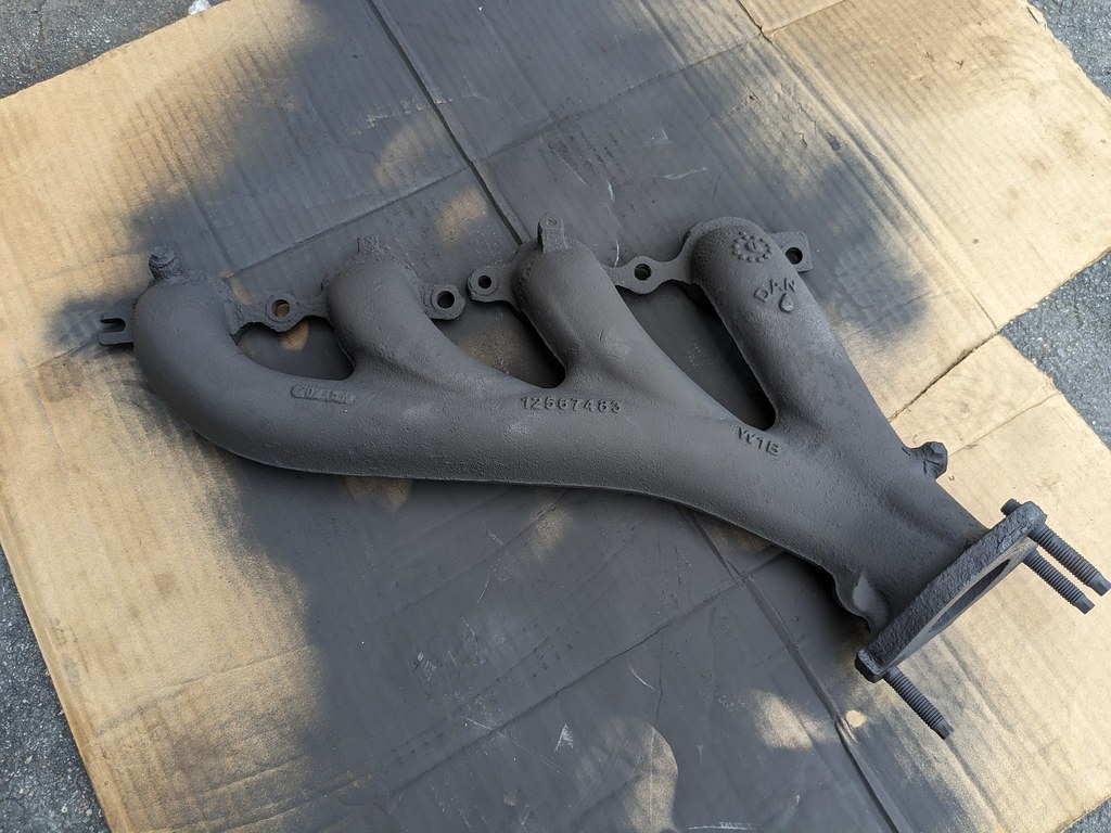
Then I did an initial test on my new passenger exhaust manifold! Unfortunately, it's going to have to wait for a while though until I can get the rest of the components to make the complete turbo kit.
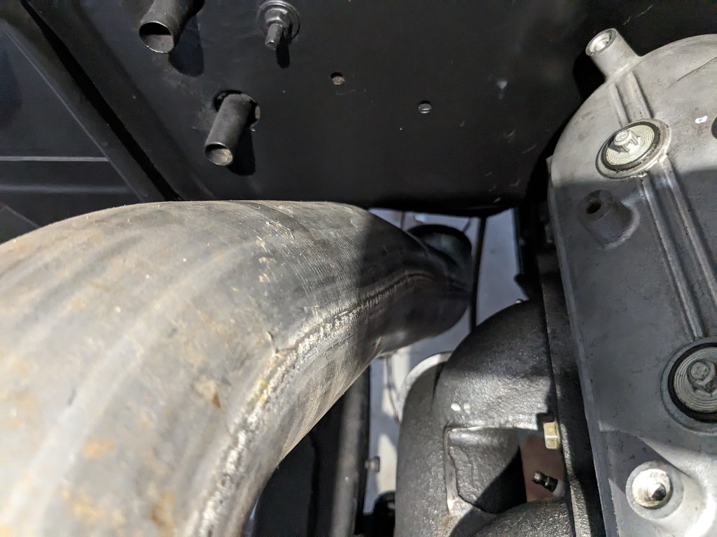
But that didn't stop me from test fitting some components on the car! So far, it looks as if the full 4" exhaust will fit in there nicely. Although the placement of the pipe isn't that close to where the turbo will actually be.

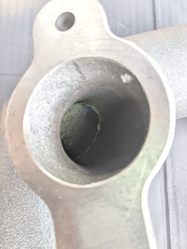
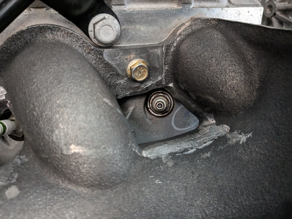
I was very pleased with the test fit, so I decided to start cleaning up the casting flash. Not did the outside need to be cleaned up allow for better plug access, the inside needed to have the flash cleaned up in order to open up the ports. There were some that had flash closing the ports by 1/2" and almost cupping flow in the wrong direction.
Not the greatest picture, but that was the flash inside one of the ports. I used my carbide bits to get the smoothest transitions that I could from the primary ports to the main section.
I couldn't get very good picture of the cleaned up ports, but you get the idea. On the outside I knocked down all the flash and had to open up some spots for plug access and dipstick clearance.

I also noticed that while the machining on the flange was really flat where it bolts to the head, the outside flange where the bolt sits was very uneven. I decided to do something about that and spot face the sections where the flange bolts sit. Here you can see just how much it was off.
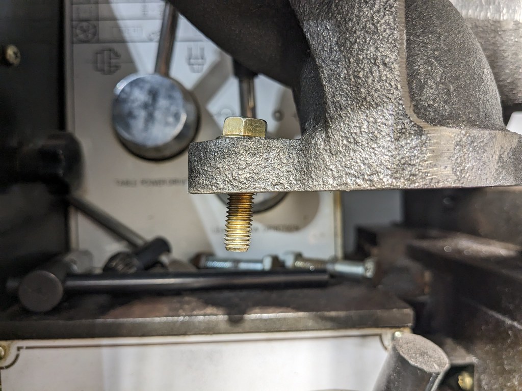
So glad that I found this Mill/Lathe a few months back.
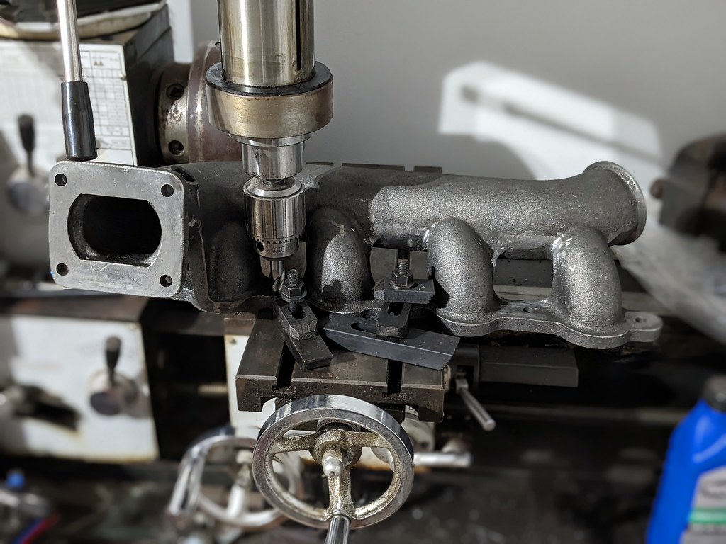

Once I got the manifold bolts spot faced, I was much happier with the fitment, longevity and bolts not loosening up. I cleaned it all up and sprayed with some high temp paint.

While I was at it, I cleaned up the TBSS exhaust manifold I had for the driver's side.
After playing around with the placement of the exhaust I came to the conclusion that without actually having the turbo mounted, I'd be shooting in the dark trying to figure out the placement. I'd probably have more work into reworking the downpipe to fit when I'm ready to swap to the turbo, that I'd be saving doing it now. So I'm putting that manifold on the parts shelf and will move forward with the truck exhaust manifolds.
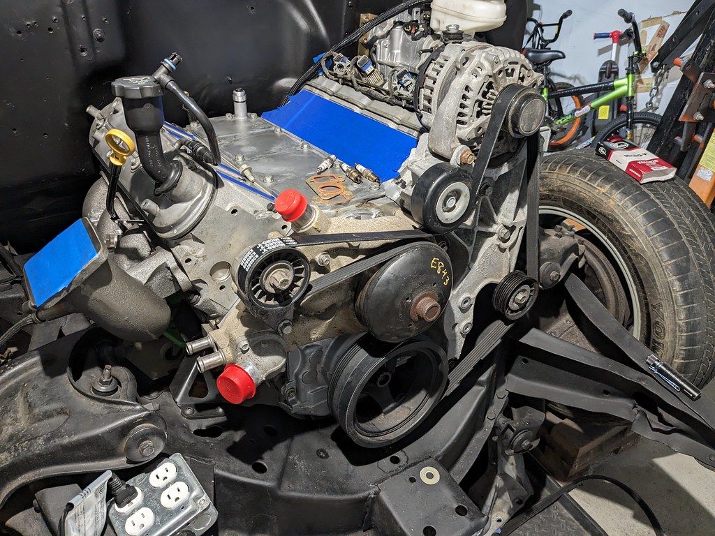
I decided to try and fit up my engine accessories. After bolting on the truck accessories and water pump, I was trying to figure out how to use what parts I have. After playing around for a while, I figured out a way to use the truck accessories with a new Fbody belt I had deleting PS since my box is manual. I robbed a tensioner pulley, idler spacer and one washer in the hole for the PS pump. Worked perfectly! The belt spacing is all at the same level so it should work perfectly for me.
Hoping to get the fuel tank installed this week and the fuel lines and wiring installed along with laying out the Terminator X Max harness.
Cheers,
Ryan
Next was installing the balancer bolt. This thing had to be torqued to 235 lb ft! Marked it to have a quick reference in the unlikely event it loosened.
Then I did an initial test on my new passenger exhaust manifold! Unfortunately, it's going to have to wait for a while though until I can get the rest of the components to make the complete turbo kit.
But that didn't stop me from test fitting some components on the car! So far, it looks as if the full 4" exhaust will fit in there nicely. Although the placement of the pipe isn't that close to where the turbo will actually be.
I was very pleased with the test fit, so I decided to start cleaning up the casting flash. Not did the outside need to be cleaned up allow for better plug access, the inside needed to have the flash cleaned up in order to open up the ports. There were some that had flash closing the ports by 1/2" and almost cupping flow in the wrong direction.
Not the greatest picture, but that was the flash inside one of the ports. I used my carbide bits to get the smoothest transitions that I could from the primary ports to the main section.
I couldn't get very good picture of the cleaned up ports, but you get the idea. On the outside I knocked down all the flash and had to open up some spots for plug access and dipstick clearance.
I also noticed that while the machining on the flange was really flat where it bolts to the head, the outside flange where the bolt sits was very uneven. I decided to do something about that and spot face the sections where the flange bolts sit. Here you can see just how much it was off.
So glad that I found this Mill/Lathe a few months back.
Once I got the manifold bolts spot faced, I was much happier with the fitment, longevity and bolts not loosening up. I cleaned it all up and sprayed with some high temp paint.
While I was at it, I cleaned up the TBSS exhaust manifold I had for the driver's side.
After playing around with the placement of the exhaust I came to the conclusion that without actually having the turbo mounted, I'd be shooting in the dark trying to figure out the placement. I'd probably have more work into reworking the downpipe to fit when I'm ready to swap to the turbo, that I'd be saving doing it now. So I'm putting that manifold on the parts shelf and will move forward with the truck exhaust manifolds.
I decided to try and fit up my engine accessories. After bolting on the truck accessories and water pump, I was trying to figure out how to use what parts I have. After playing around for a while, I figured out a way to use the truck accessories with a new Fbody belt I had deleting PS since my box is manual. I robbed a tensioner pulley, idler spacer and one washer in the hole for the PS pump. Worked perfectly! The belt spacing is all at the same level so it should work perfectly for me.
Hoping to get the fuel tank installed this week and the fuel lines and wiring installed along with laying out the Terminator X Max harness.
Cheers,
Ryan
Thread Starter
Joined: Apr 2012
Posts: 2,171
Likes: 716
From: Ruckersville, VA
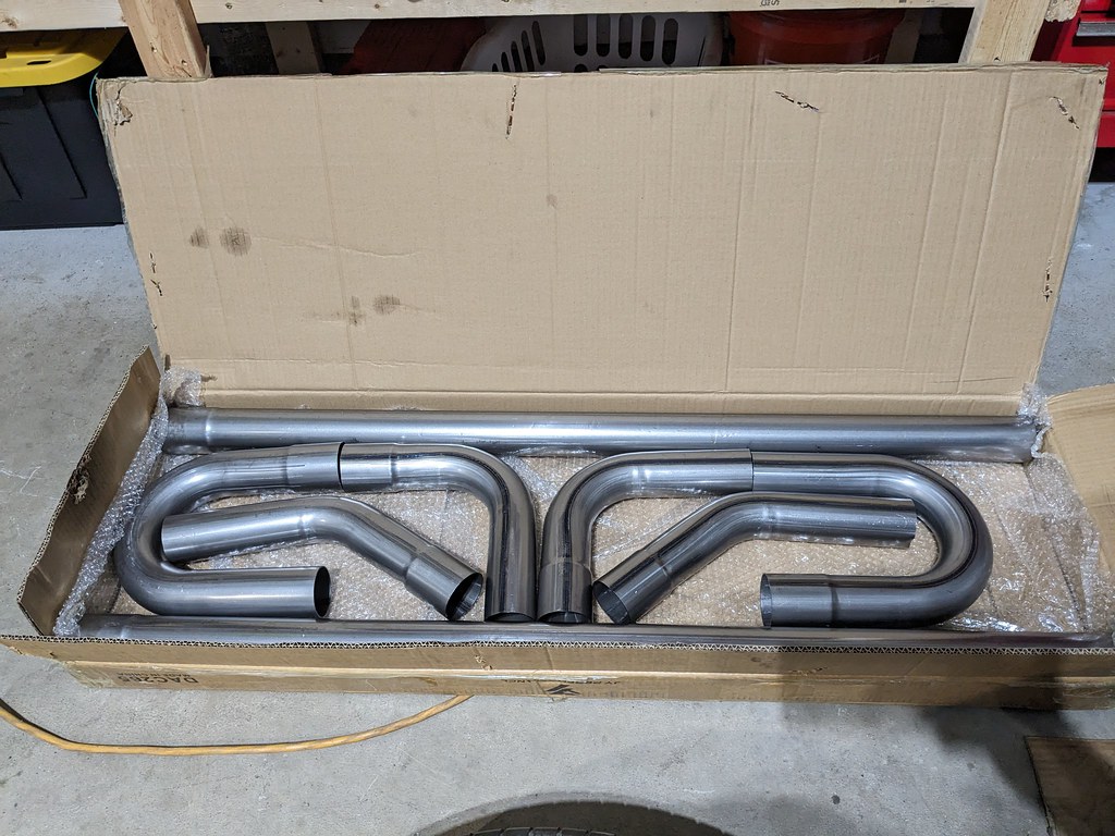
This project is starting to wear me out, so I really need a pick me up. I decided to hold off on mocking up the turbo manifold and downpipe until I'm ready with the turbo that I plan to run. I think I'll end up with much less work down the road. I swapped it out for a stock truck manifold that I had on the shelf. I used some of the flanges from Summit and a basic universal 2.5" exhaust kit from eBay.
Was very impressed by the symmetry of the packaging on this kit. The pipes are nice too but just mild steel.
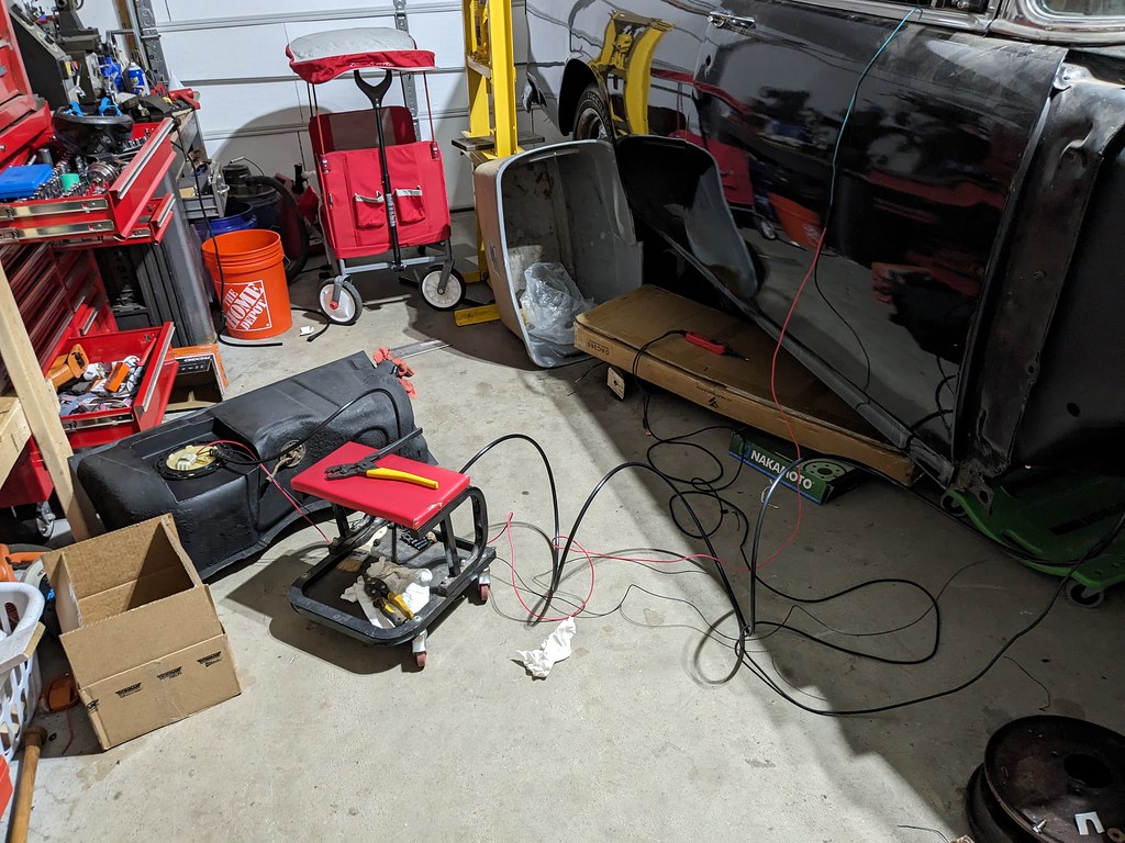
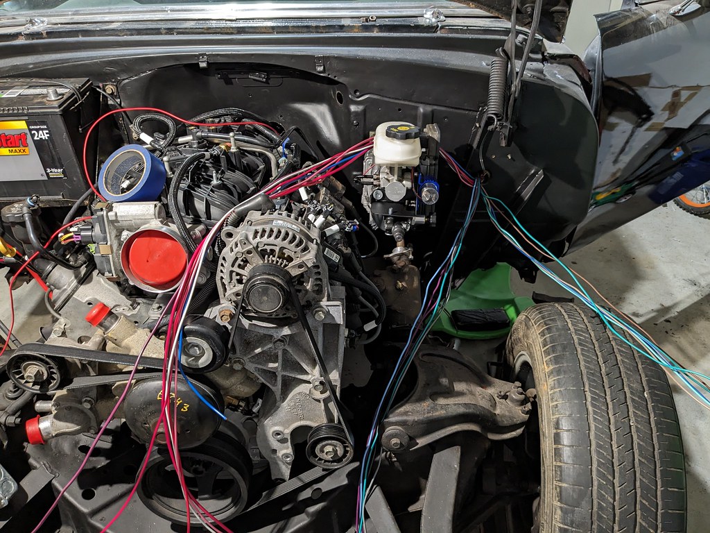
Then it was time to start bolting parts back on. Battery back on the firewall and started to layout some extra battery cables I've kept over the years to see what is going to work. Thankfully I found a few that will work perfectly for me.
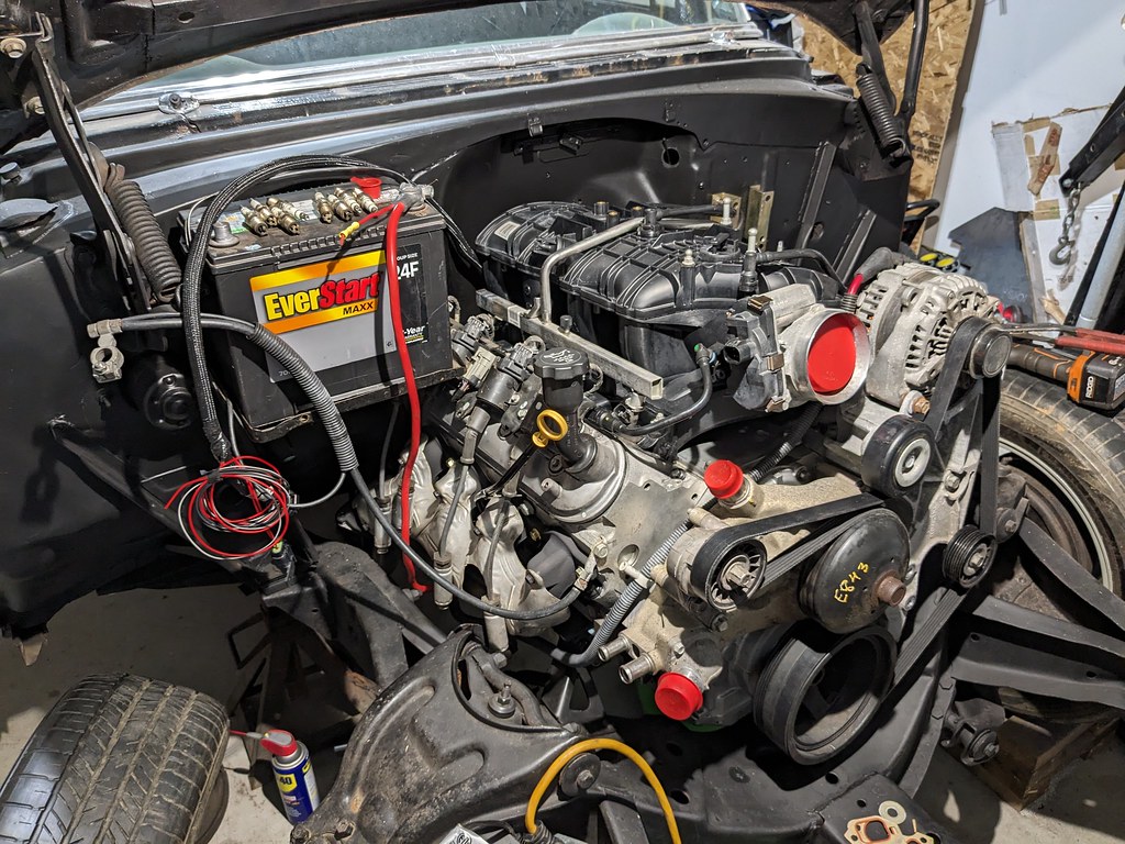
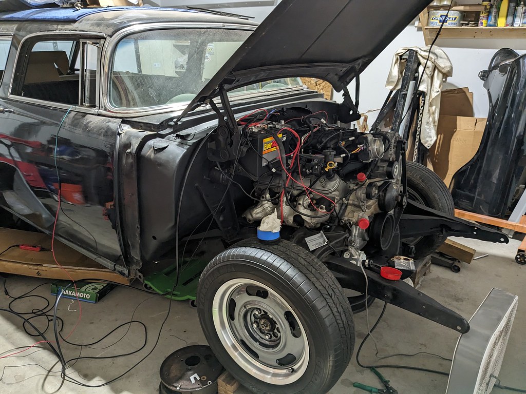
With that all mocked up, it was time to cut the giant hole in the firewall for the EFI components. I removed the intake and covered all the ports before I started drilling. I just removed them all for the picture. I also made sure to center the hole from the inside to make sure that it would clear everything under the dash too. I'm very happy with that position and need to track down a nice grommet for it.

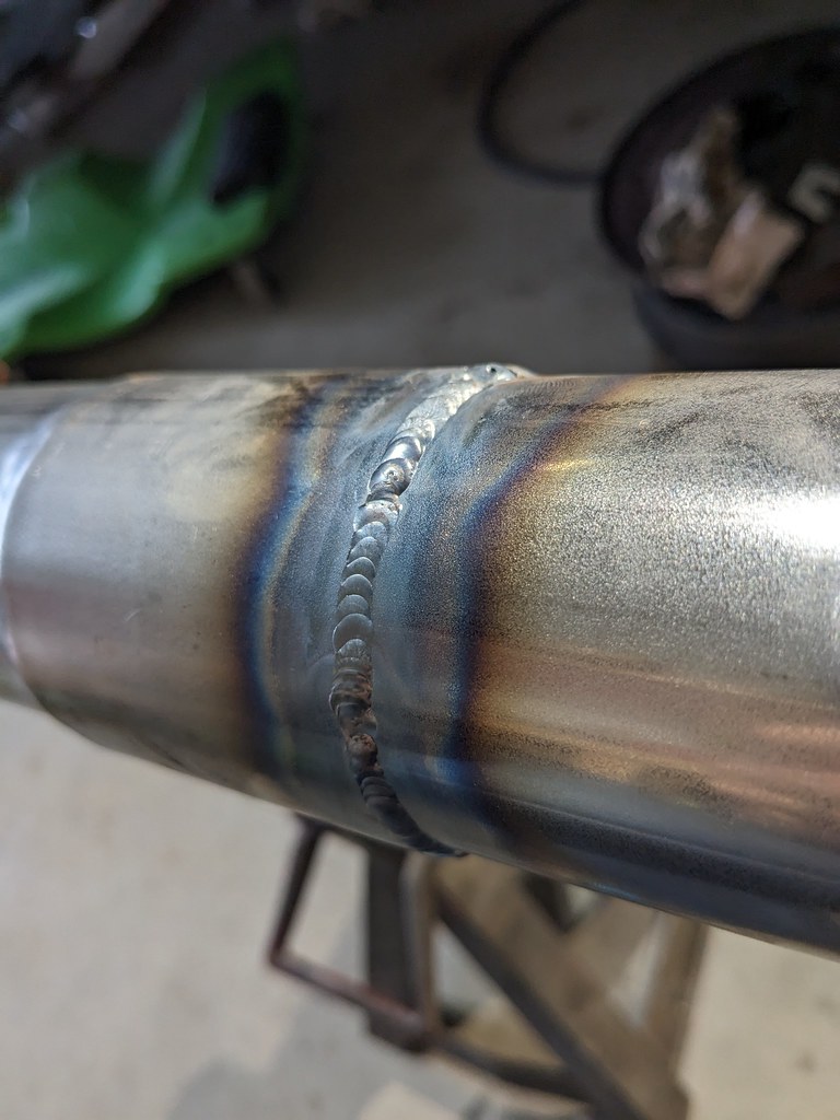
Then it was time to start getting an exhaust run so that I wasn't shooting flames out of the manifolds. I used the MIG to get a few tack welds on the flanges and the straight pipe, then pulled it off and finished the rest with my TIG. Trying to get better, so trying to get more seat time. I really need a proper welding table to do this at, but for now some jack stands worked ok. I'm starting to see some more consistency, but still need to move faster so have less heat.
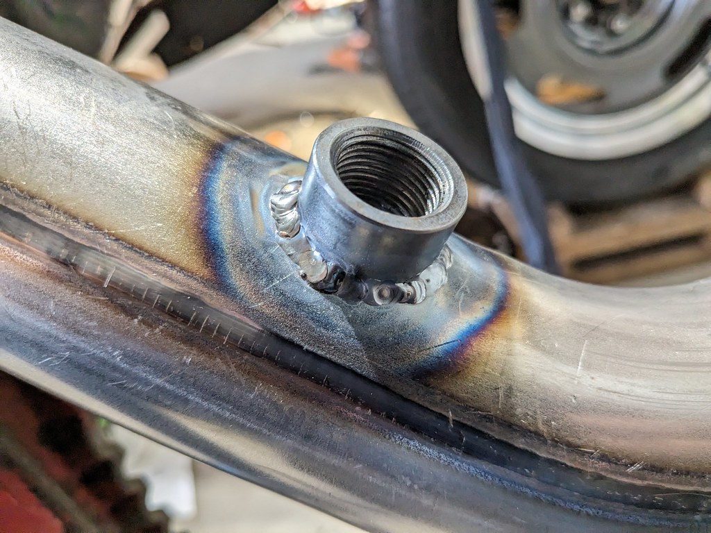
When those two connections were welded up, I reinstalled to mark where the O2 sensor will live. Found a nice spot, marked it, and removed to weld it all up.
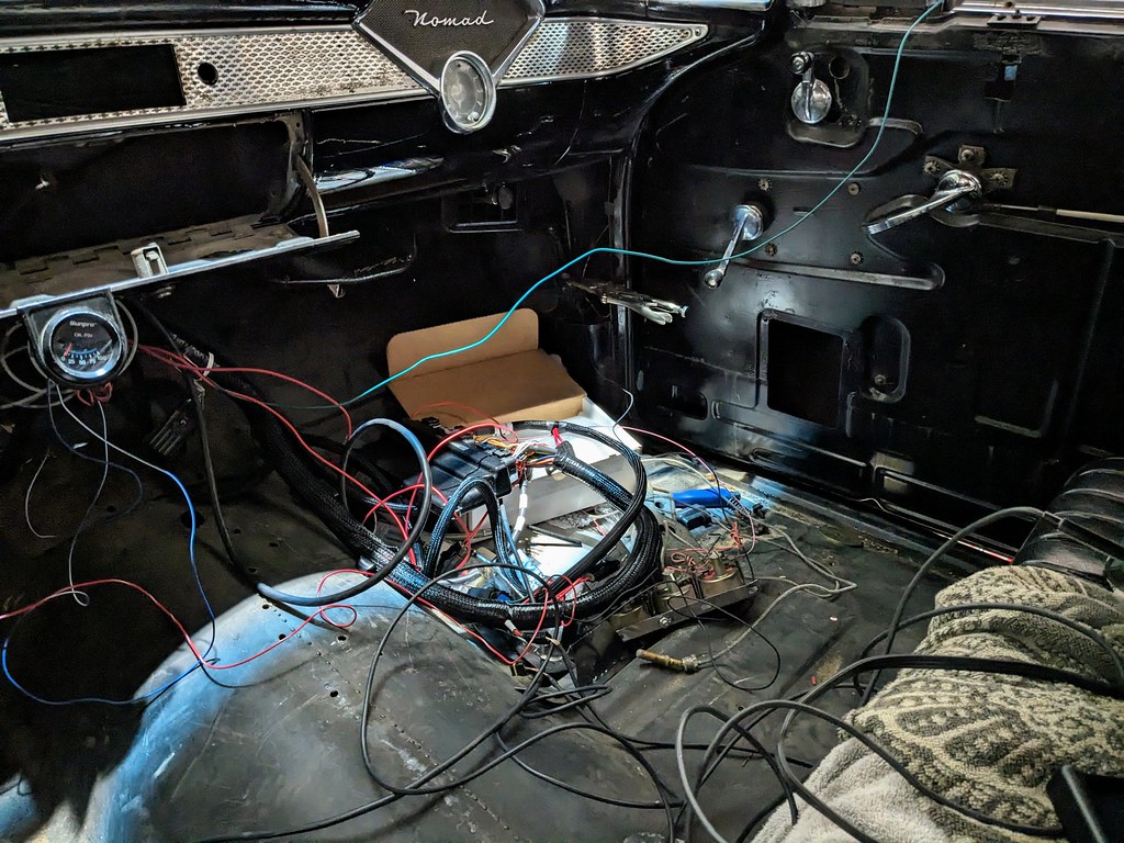
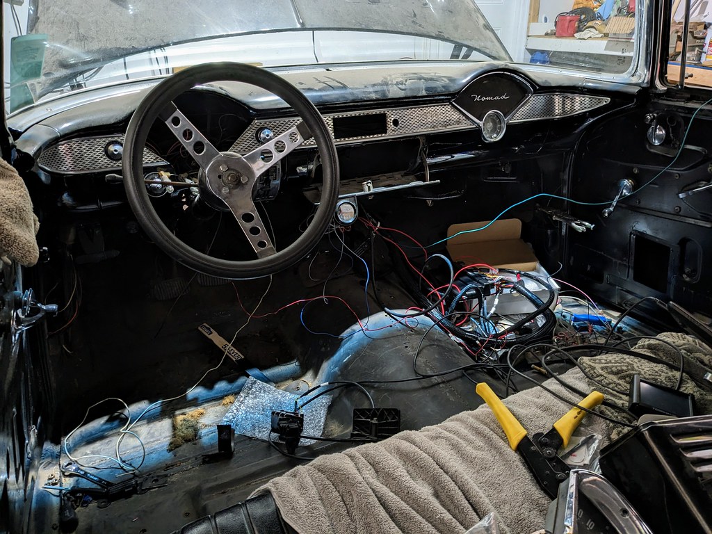
After this point, I was just busy bouncing around making connections, converting the Terminator X harness to LS3 MAP pigtail, tracking down wires (specifically a 12v switched that stayed on when cranking), making fuel lines, crimping wires, testing wires, and etc. With the goal being able to crank and fire the engine this weekend. I got so busy that I didn't take any pictures so these were taken this morning after I got my coffee.
I've used this method for every LS swap I've done. It allows me to check for leaks and wiring prior to installation.
Very crudely wired everything up. Lot's of crazy wires all over, but it was either taped up or away from anything hot.
All of my Terminator wiring spread out for easy access. You can also see my temporary mechanical oil pressure gauge.
After a lot of playing around with my start up tune, I was able to get the right combination and the TPS wizard was successful. Turns out I never added the DBW component to my tune, which is pretty important. Confirmed fuel pressure, then gave it a few cranks. It sputtered a few times, then fired off. Kept a close eye on oil pressure and within 5 seconds it was fluttering around 25, and then after about 10 seconds had full 50 psi. Sweet! I couldn't run the car very long at all since there was no radiator and the torque converter was disconnected, but it was a huge win for my weekend!
So happy that the motor is running and had great oil pressure. I gave it a few revs at the end, but the fuel maps were just a base map that Holley provided. I also used a 2.5bar LSA map sensor, but something must be off because it was reading 117 kpa key on engine off. I'm sure there are other things too, but I am very pleased given how little run time the car has. I need to get the radiator and transmission installed so I can get the engine up to operating temperature and let the learn clean up the VE table a bit.
Cheers,
Ryan
Was very impressed by the symmetry of the packaging on this kit. The pipes are nice too but just mild steel.
Then it was time to start bolting parts back on. Battery back on the firewall and started to layout some extra battery cables I've kept over the years to see what is going to work. Thankfully I found a few that will work perfectly for me.
With that all mocked up, it was time to cut the giant hole in the firewall for the EFI components. I removed the intake and covered all the ports before I started drilling. I just removed them all for the picture. I also made sure to center the hole from the inside to make sure that it would clear everything under the dash too. I'm very happy with that position and need to track down a nice grommet for it.
Then it was time to start getting an exhaust run so that I wasn't shooting flames out of the manifolds. I used the MIG to get a few tack welds on the flanges and the straight pipe, then pulled it off and finished the rest with my TIG. Trying to get better, so trying to get more seat time. I really need a proper welding table to do this at, but for now some jack stands worked ok. I'm starting to see some more consistency, but still need to move faster so have less heat.
When those two connections were welded up, I reinstalled to mark where the O2 sensor will live. Found a nice spot, marked it, and removed to weld it all up.
After this point, I was just busy bouncing around making connections, converting the Terminator X harness to LS3 MAP pigtail, tracking down wires (specifically a 12v switched that stayed on when cranking), making fuel lines, crimping wires, testing wires, and etc. With the goal being able to crank and fire the engine this weekend. I got so busy that I didn't take any pictures so these were taken this morning after I got my coffee.
I've used this method for every LS swap I've done. It allows me to check for leaks and wiring prior to installation.
Very crudely wired everything up. Lot's of crazy wires all over, but it was either taped up or away from anything hot.
All of my Terminator wiring spread out for easy access. You can also see my temporary mechanical oil pressure gauge.
After a lot of playing around with my start up tune, I was able to get the right combination and the TPS wizard was successful. Turns out I never added the DBW component to my tune, which is pretty important. Confirmed fuel pressure, then gave it a few cranks. It sputtered a few times, then fired off. Kept a close eye on oil pressure and within 5 seconds it was fluttering around 25, and then after about 10 seconds had full 50 psi. Sweet! I couldn't run the car very long at all since there was no radiator and the torque converter was disconnected, but it was a huge win for my weekend!
So happy that the motor is running and had great oil pressure. I gave it a few revs at the end, but the fuel maps were just a base map that Holley provided. I also used a 2.5bar LSA map sensor, but something must be off because it was reading 117 kpa key on engine off. I'm sure there are other things too, but I am very pleased given how little run time the car has. I need to get the radiator and transmission installed so I can get the engine up to operating temperature and let the learn clean up the VE table a bit.
Cheers,
Ryan

Congrats on the start - always makes the rest of the build go quicker.
You might consider running the car NA and shaking down any other bugs before you go turbo. I did that on my Crown Vic build, drove it NA for a few months while I gathered the parts.
You might consider running the car NA and shaking down any other bugs before you go turbo. I did that on my Crown Vic build, drove it NA for a few months while I gathered the parts.
Thread Starter
Joined: Apr 2012
Posts: 2,171
Likes: 716
From: Ruckersville, VA
Thanks man! You're right, I'm going to run in N/A mode for the time being and collect turbo parts for the next little while. Hoping to get the last few remaining parts so that I can get it out and moving under it's own power.

Thread Starter
Joined: Apr 2012
Posts: 2,171
Likes: 716
From: Ruckersville, VA
It was a huge relief to know that the motor is running and that I could move on with getting everything else completed to take the maiden voyage! I'll be working on the brakes and wiring next. After inspecting what's left of my original wiring harness I came to the conclusion that I needed to upgrade. I've never used one of the harnesses from eBay but given the cost of one vs a Painless or AAW, I took a chance on this one.
I had heard that the wiring was cheap and not as thick of gauge, but I found that to be not true. I was actually impressed with all the gauge thicknesses and overall it was a great value. The terminals look a little on the thin side, but overall they do fit nicely and should work great. One thing that is a little frustrating is that while all the wires are labelled, some of the printing is very faint. Either faint or rather than being labelled every 12", it's maybe every 30". But, I was able to at least find a label for every wire, so it's a minor inconvenience.
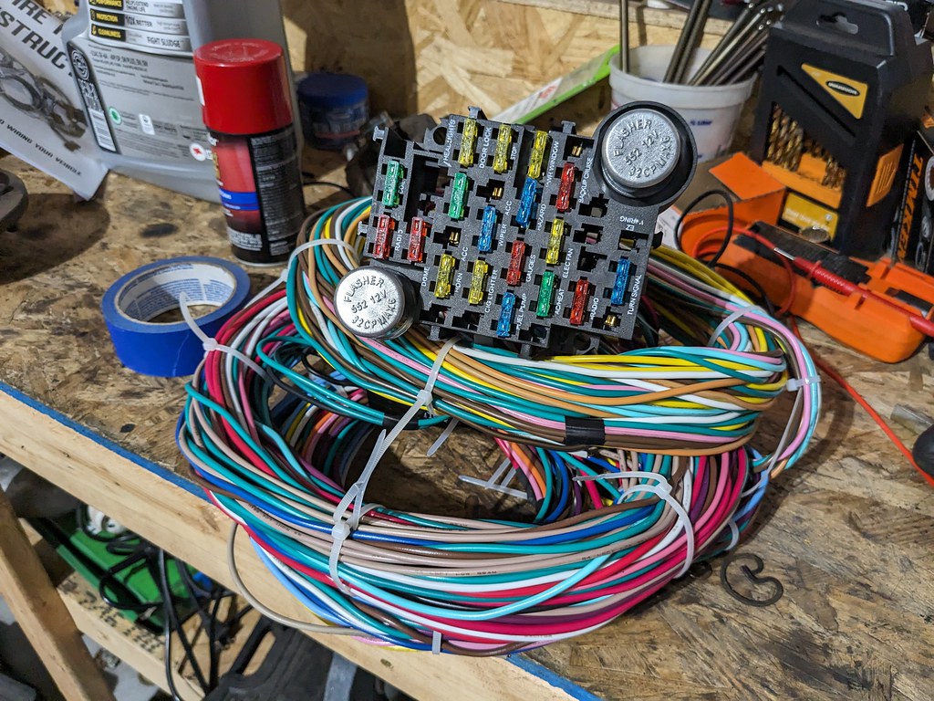
Out with the old. It's really amazing that the cars ran on only a few fuses. The wires were all cracking and breaking when I went to remove them, so I'm happy that I made the choice to replace.

Found a nice spot and used the existing hole to route the engine wires through.
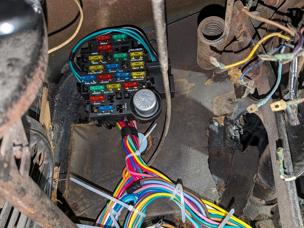
That's where the fun began. The wires are labelled, but some were very hard to find or hard to read. Once I got the harness bulkhead location locked in, I started to organize all of the wires and fed them to where they needed to go in groups. Gauges, head lights, etc.

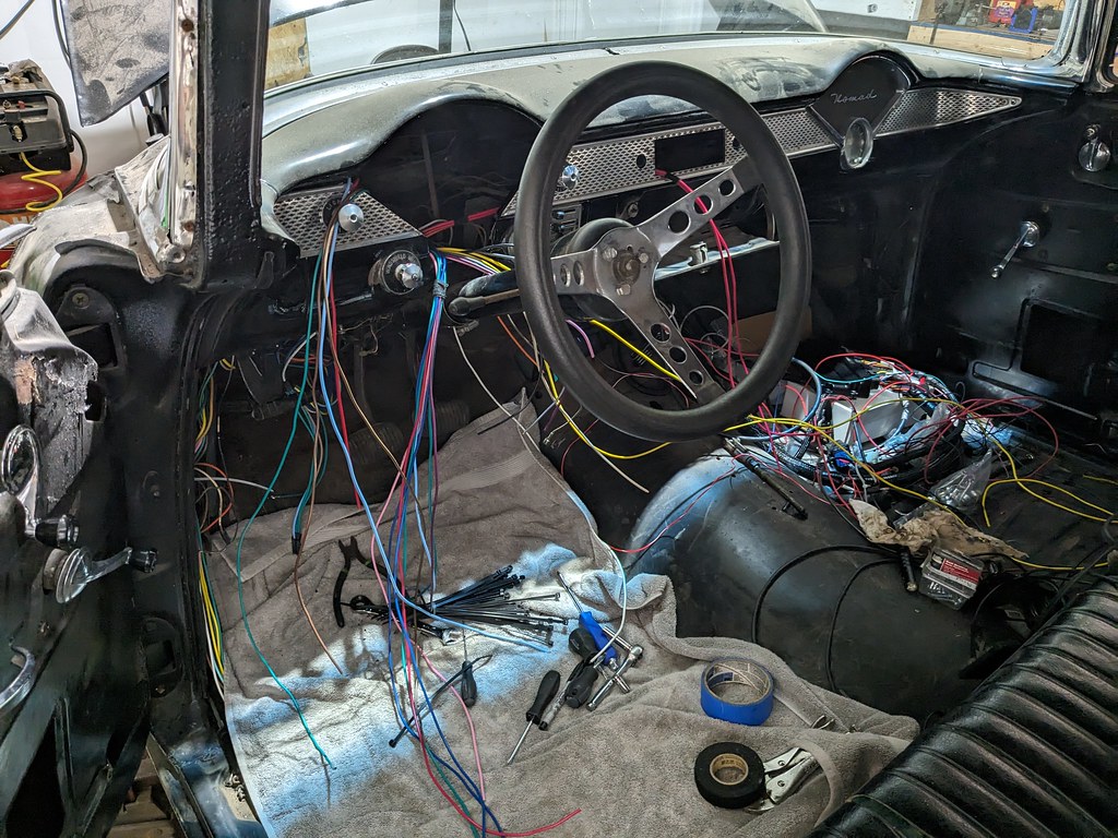
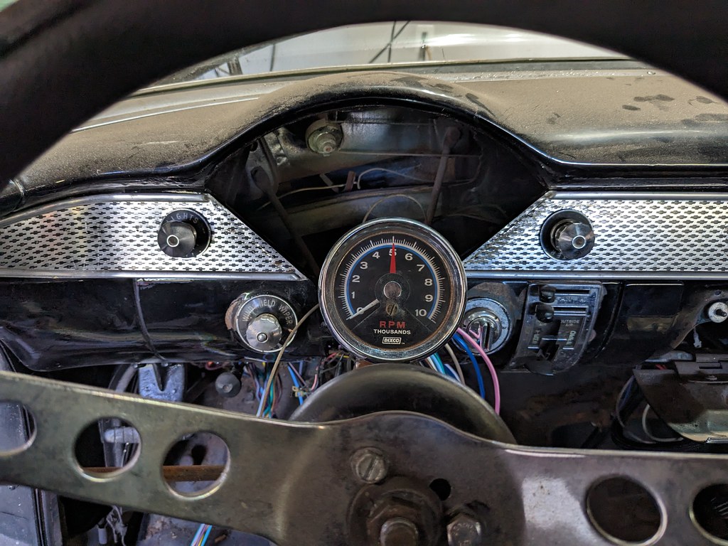
I've been wanting a vintage tach for the steering column, and my father in law just removed the one from his '56 Belair, so I put this on the column quick. That's just the look I want, but I'll rotate it down to the left about 45*.
I was able to get the ignition wiring hooked up so that I could test out the circuits to confirm that it's all working as it should. One thing that I found out was that on the 55-56 ignition switches, the IGN-1 and IGN-2 activate at different positions on the key. #1 is hot with the key on, but #2 is off key on. Then they switch in the start position, so a common thing guys did back in the day when swapping to HEI is to jumper the two together. So that's my plan, but I'm not sure exactly how I want to accomplish that. With a jumper wire on the switch itself or just tie them both together further up in the wiring.
I jumped around during this phase, but I was simultaneously working on the bracket for swapping to the Tesla brake booster. I had to add a radius to the inside of the bracket for the booster to clear. Took the opportunity to chuck it into my mill and used a whole saw. Probably better ways to do that, but this worked perfectly and quickly.

Now that the bracket is finalized, I added some gussets and TIG welded it all back together. I forgot to take a picture of it, but there wasn't much to write home about. I think I'd like to remake the bracket from scratch at some point, but for now it will work great. My next task was figuring out how to mount the Wilwood proportional valve and line lock kit. I came up with a pretty simple bracket that mounts to the brake MC where the prop valve is on the bottom and the line lock mounts to the side.


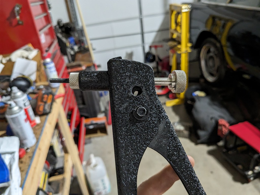
I got to this point and got out my rivnut tool from Harbor Freight. Some things are great from that store and others aren't. This is basically a modified rivet tool that was reworked for installing rivnuts. It got worn out from the last time I used it and had so much slop in it that I wasn't able to get enough throw to compress the nut. So after some thought, I modified the pivot hole to give me more throw. Worked great and fully compresses the rivnuts.

Once the rivnuts were installed, I was able to test fit it all together. I'm very happy with the layout and can't wait to get some lines on it and bolt it down. I'll be painting the blue anodized parts black, but for now it's all test fit in there.
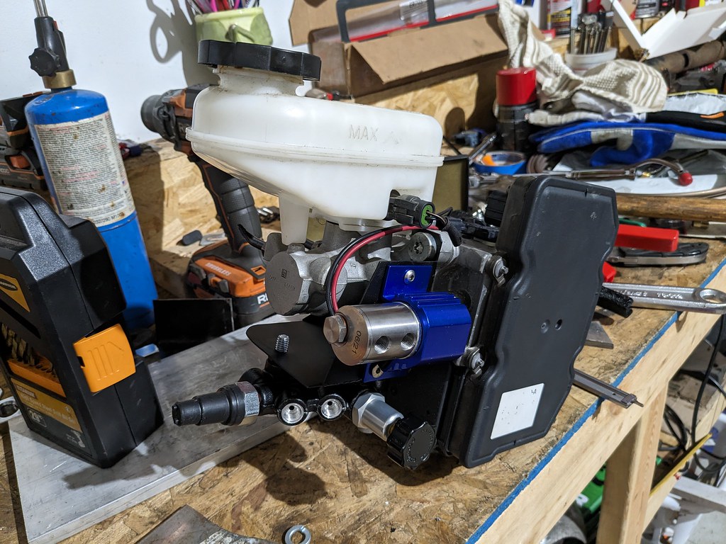
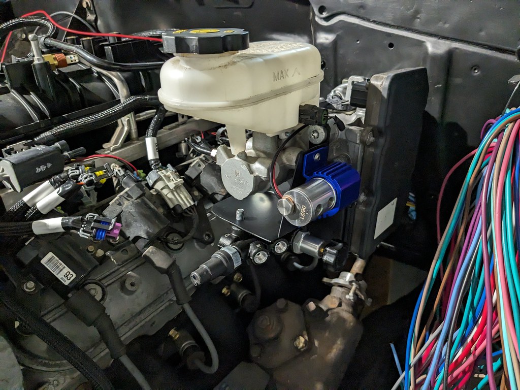
My next obstacle is to find some brake fittings that will work with the iBooster. They have M12x1 inverted flare fittings with 6mm lines and I need to adapt those to 3/8" with 3/16" lines. I bought a set of M12x1 fittings made for 3/16" lines, but I've heard that the flares may not be big enough to seal with the opening of the MC. I'm going to give it a shot since this would be the simplest way for me, but if it doesn't seal, I'll have to get some adapters or something. I also need to make a plan to finalize the booster rod, but I'm going to use the original '55 rod, and weld it to the nut that came with the booster. I'll also need to drill a new hole lower on the brake pedal to give a better throw angle. Much more to come.
Cheers,
Ryan
I had heard that the wiring was cheap and not as thick of gauge, but I found that to be not true. I was actually impressed with all the gauge thicknesses and overall it was a great value. The terminals look a little on the thin side, but overall they do fit nicely and should work great. One thing that is a little frustrating is that while all the wires are labelled, some of the printing is very faint. Either faint or rather than being labelled every 12", it's maybe every 30". But, I was able to at least find a label for every wire, so it's a minor inconvenience.
Out with the old. It's really amazing that the cars ran on only a few fuses. The wires were all cracking and breaking when I went to remove them, so I'm happy that I made the choice to replace.
Found a nice spot and used the existing hole to route the engine wires through.
That's where the fun began. The wires are labelled, but some were very hard to find or hard to read. Once I got the harness bulkhead location locked in, I started to organize all of the wires and fed them to where they needed to go in groups. Gauges, head lights, etc.
I've been wanting a vintage tach for the steering column, and my father in law just removed the one from his '56 Belair, so I put this on the column quick. That's just the look I want, but I'll rotate it down to the left about 45*.
I was able to get the ignition wiring hooked up so that I could test out the circuits to confirm that it's all working as it should. One thing that I found out was that on the 55-56 ignition switches, the IGN-1 and IGN-2 activate at different positions on the key. #1 is hot with the key on, but #2 is off key on. Then they switch in the start position, so a common thing guys did back in the day when swapping to HEI is to jumper the two together. So that's my plan, but I'm not sure exactly how I want to accomplish that. With a jumper wire on the switch itself or just tie them both together further up in the wiring.
I jumped around during this phase, but I was simultaneously working on the bracket for swapping to the Tesla brake booster. I had to add a radius to the inside of the bracket for the booster to clear. Took the opportunity to chuck it into my mill and used a whole saw. Probably better ways to do that, but this worked perfectly and quickly.
Now that the bracket is finalized, I added some gussets and TIG welded it all back together. I forgot to take a picture of it, but there wasn't much to write home about. I think I'd like to remake the bracket from scratch at some point, but for now it will work great. My next task was figuring out how to mount the Wilwood proportional valve and line lock kit. I came up with a pretty simple bracket that mounts to the brake MC where the prop valve is on the bottom and the line lock mounts to the side.
I got to this point and got out my rivnut tool from Harbor Freight. Some things are great from that store and others aren't. This is basically a modified rivet tool that was reworked for installing rivnuts. It got worn out from the last time I used it and had so much slop in it that I wasn't able to get enough throw to compress the nut. So after some thought, I modified the pivot hole to give me more throw. Worked great and fully compresses the rivnuts.
Once the rivnuts were installed, I was able to test fit it all together. I'm very happy with the layout and can't wait to get some lines on it and bolt it down. I'll be painting the blue anodized parts black, but for now it's all test fit in there.
My next obstacle is to find some brake fittings that will work with the iBooster. They have M12x1 inverted flare fittings with 6mm lines and I need to adapt those to 3/8" with 3/16" lines. I bought a set of M12x1 fittings made for 3/16" lines, but I've heard that the flares may not be big enough to seal with the opening of the MC. I'm going to give it a shot since this would be the simplest way for me, but if it doesn't seal, I'll have to get some adapters or something. I also need to make a plan to finalize the booster rod, but I'm going to use the original '55 rod, and weld it to the nut that came with the booster. I'll also need to drill a new hole lower on the brake pedal to give a better throw angle. Much more to come.
Cheers,
Ryan
Looking great Ryan. I think your progress is phenomenal. This was quite an undertaking so I get the wear you out part of it.
You got the fancy welder I see lol. I do all of my exhaust work with my dumb ole MIG welder. Even on stainless.
You got the fancy welder I see lol. I do all of my exhaust work with my dumb ole MIG welder. Even on stainless.
Thread Starter
Joined: Apr 2012
Posts: 2,171
Likes: 716
From: Ruckersville, VA
Thanks Steve, I really appreciate it. I'm really starting to see the light at the end of the tunnel and can't wait to get the car moving under it's own power!
Joined: Aug 2007
Posts: 2,455
Likes: 129
From: Where the Navy tells me to go
Got a link to the wiring harness / fuse panel that you got off Ebay? I'm sure there are a million listings, so it'll be good to have a reference for one that someone has actually laid eyes on and given mostly positive feedback.

Andrew
Thread Starter
Joined: Apr 2012
Posts: 2,171
Likes: 716
From: Ruckersville, VA
I agree, but thought that I'd give this a try and see how it goes. I wouldn't have installed it if I questioned it's reliability. If I have issues down the road, I can always swap out for a name brand harness.
So far the Amazon gen 3 cable throttle body harness I bought every single connector functions correctly. with no anomalies.
Thread Starter
Joined: Apr 2012
Posts: 2,171
Likes: 716
From: Ruckersville, VA
Progress has been a little slow as I've been working on a few house projects. I think it was actually a good thing because I needed a little break from the car. I started too many projects at once and got a bit overwhelmed. Over the weekend I finally tackled something that had been bugging me, the body wasn't centered on the frame. Without a lift, I wasn't sure how I was going to accomplish this, but after overthinking it for so long, it was an easy solution. Loosen/remove the body bolts, jack the whole car up, then put some jack stands on the body, then lower it down to lift the body off the frame. Then I used some ratchet straps to pull the body in the direction that I needed it to be. After some careful measuring and shifting around, I was able to get it centered within 1/8". It ended up being that the rear of the car was shifted to the driver's side about 1/2"! After I moved it, the wheels and bumper fit so much better. No pictures as I was busy shifting the body and really wasn't much to see.
I really want the interior of the car to be very stock, so my plan has been to keep the stock steering column and connect it using the stock shift linkage. Someone down the line of owning my car converted my column to a floor shift by deleting the shift linkage, and welding the shifter hole shut. I tore apart a stock column I got from a junkyard, and while some components were good, most were very rusty at the lower section. Then when I was on the Tri-5 site, I saw a guy who was giving away a stock column and inner shift tube! I contacted him and he also had some other things like a shift lens, that he wasn't using. Thanks Craig!

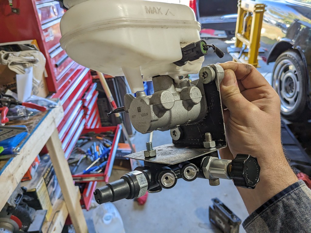
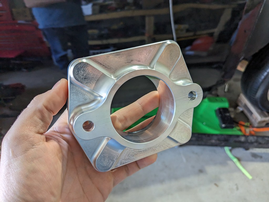
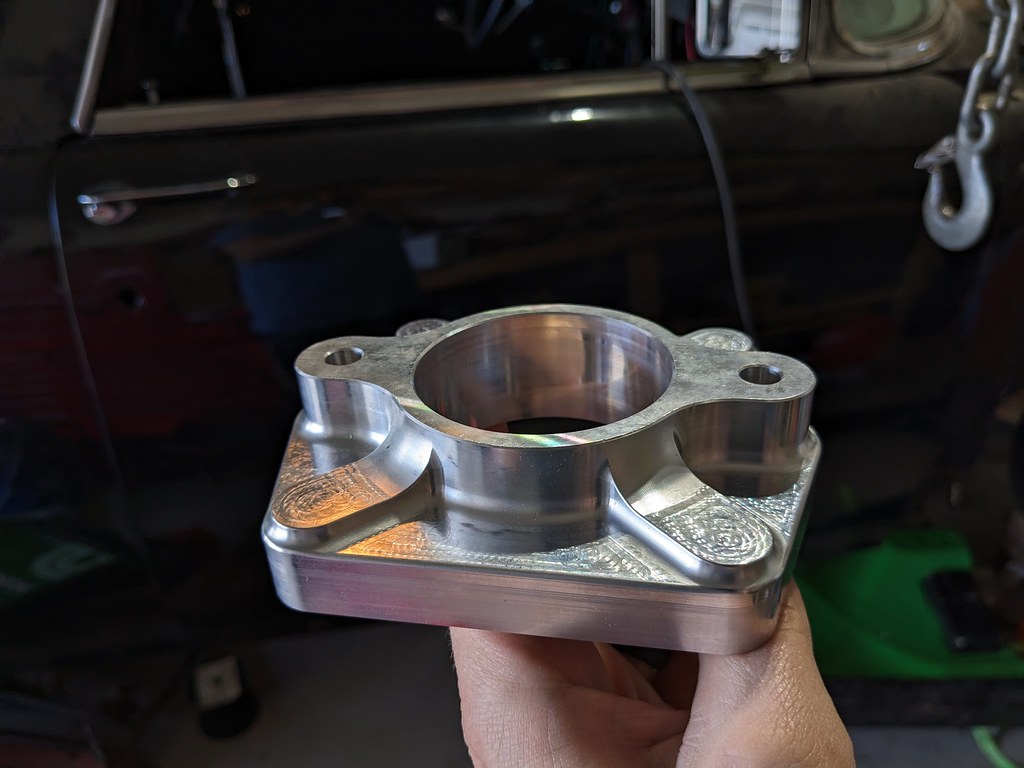
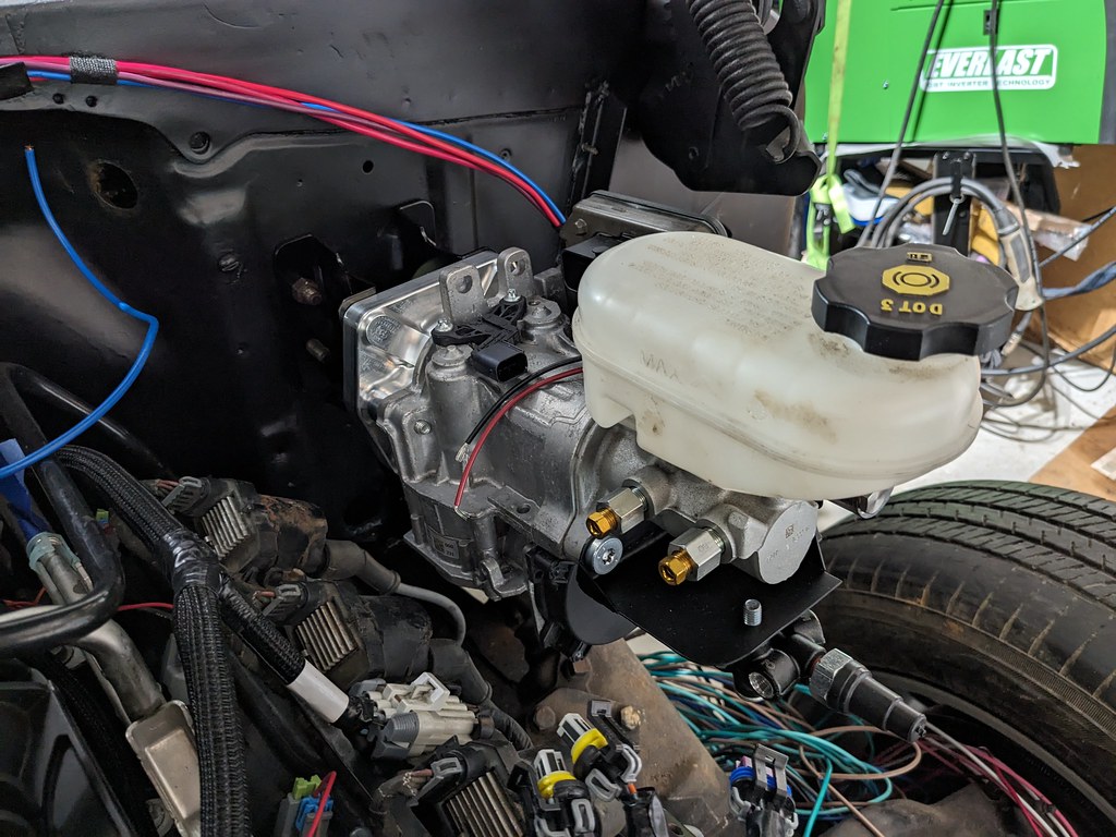
I've also been conflicted on what to do with my brake booster brackets and finding an adapter for the M12 inverted flares. The bracket that I made, didn't turn out the way that I was hoping and I wasn't sure what I wanted to do. I sent a message to a guy from Retrofit Solutions who deals with the gen1 and gen2 iBooster installations and he had a pair of M12 to 3/8" adapters that use 3/16" lines! Not only that he had a few of the BBT iBooster adapters that bolt on, but have the standard GM brake booster bolt pattern! I couldn't wait to install the booster now that I had the right parts. I also ordered a pair of generic Summit Branded brake booster brackets which turned out to have Tuff Stuff stamped on the side.
Those BBT Adapters are really impressive and the CNC work is outstanding.
Here are the brake line adapters. Really nice pieces.

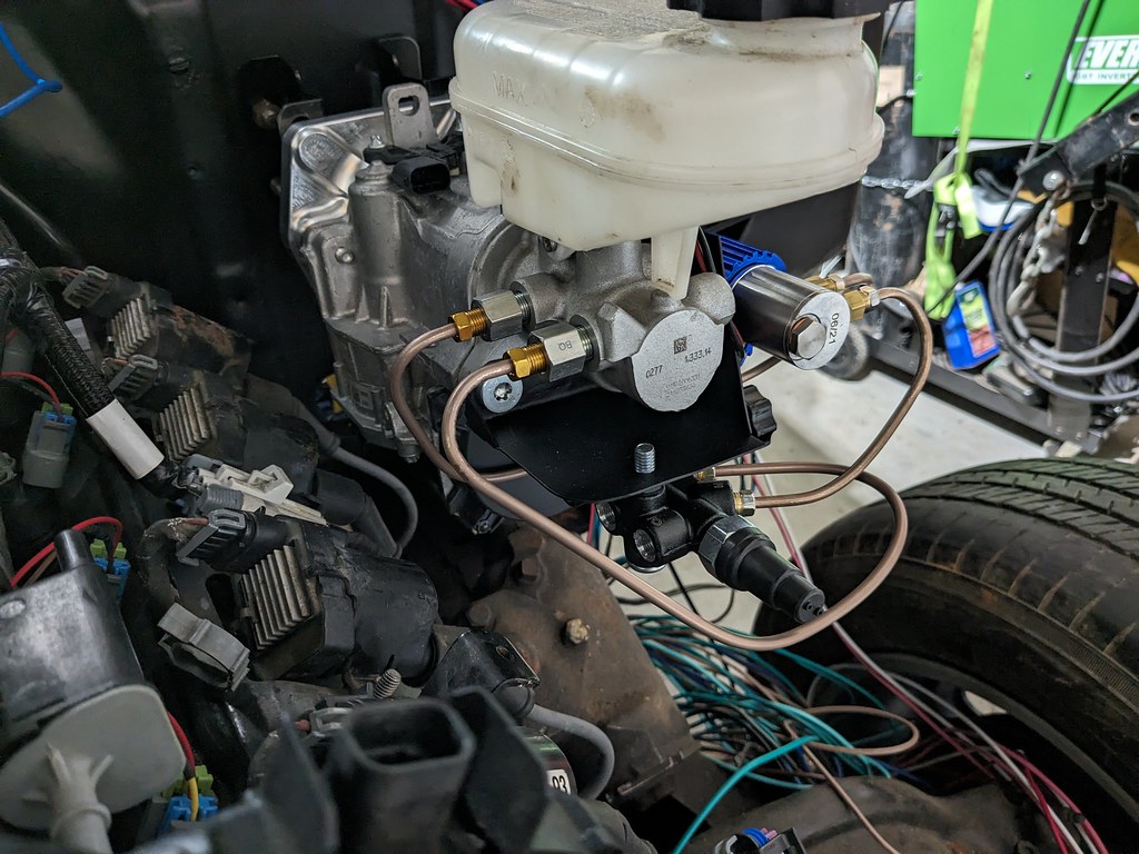
Very pleased with how the install went. I shouldn't have wasted time making my own brackets when these made the job so much easier and turned out 10x nicer.

Then I broke out my brake flaring tool. I bought this almost 2 years ago when I found it on eBay mislabeled and got it for a smoking deal. I didn't even have a need for it, but knew that I would at some point. The time has now come! It can flare a variety of different fittings, such as GM quick connect fuel lines, GM/Chrysler transmission lines with o-rings, and both inverted and bubble flare brake lines. Time to make some brake lines!
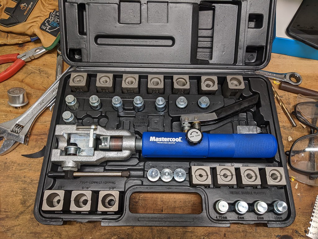
Does a really consistent job making the flares, especially with the soft NiCopp lines.
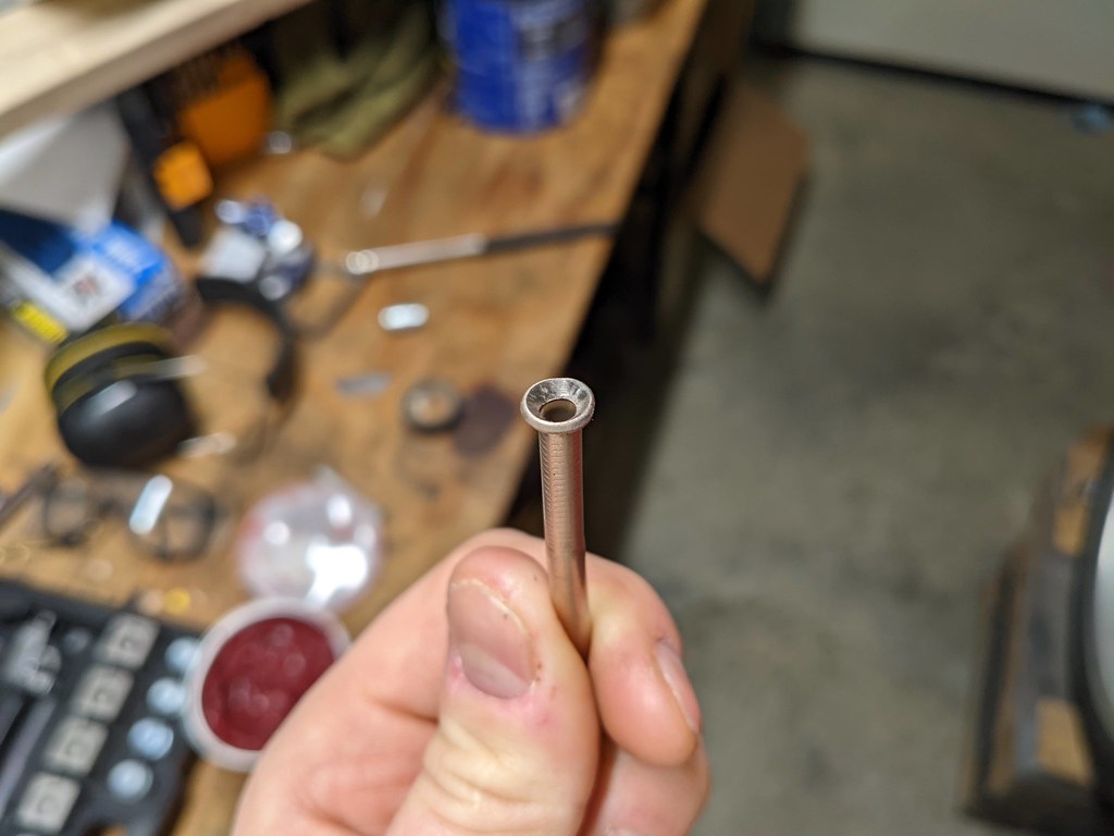
Fuel lines
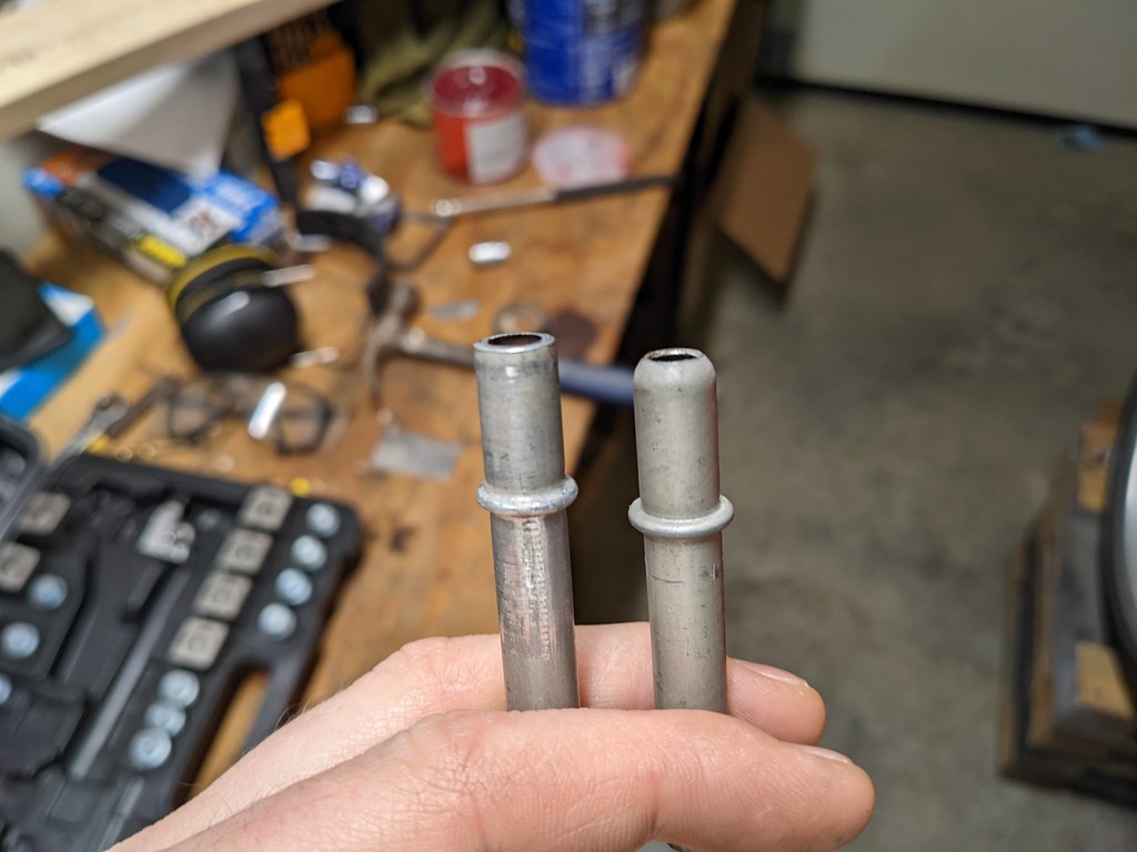
Transmission lines. I'll be using these when I make lines for my 4L80e.

It took me a while to think through how I wanted to connect all the lines together because the front port of the MC is actually the rear and vice versa. I'm really happy with how they turned out with nice swooping curves. I'll sweep the two front and one rear lines using the same method making a 180* then to their respective locations.
Can someone clarify for me what the consensus is for using sealant or no sealant on brake line fittings to the line lock? I've read some that say to use a brake line specific sealer, while other say that the tapered threads will seal without issue.

Lastly I was able to find a transmission dipstick that will work for me. I had planned to use a stock one, but I was having a difficult time tracking one down. I found that Allstar made a LS to 4L80e dipstick so I picked that up. Part number 69119. I had to bent it just slightly forward to avoid hitting the firewall, but will be serviceable yet hidden under the battery tray, so I'm happy.
I also ordered a 32 spline 1350 transmission yoke from Summit, and the appropriate adapter ujoint for my stock driveshaft. Once the brake lines are wrapped up, I can re-install the front clip and finish up the wiring. I'll also be working on the steering column shifter linkage and getting that connected to my transmission. If I can get that all done in the next few weeks, it's likely I may be taking the car up and down the block!
Cheers,
Ryan
I really want the interior of the car to be very stock, so my plan has been to keep the stock steering column and connect it using the stock shift linkage. Someone down the line of owning my car converted my column to a floor shift by deleting the shift linkage, and welding the shifter hole shut. I tore apart a stock column I got from a junkyard, and while some components were good, most were very rusty at the lower section. Then when I was on the Tri-5 site, I saw a guy who was giving away a stock column and inner shift tube! I contacted him and he also had some other things like a shift lens, that he wasn't using. Thanks Craig!
I've also been conflicted on what to do with my brake booster brackets and finding an adapter for the M12 inverted flares. The bracket that I made, didn't turn out the way that I was hoping and I wasn't sure what I wanted to do. I sent a message to a guy from Retrofit Solutions who deals with the gen1 and gen2 iBooster installations and he had a pair of M12 to 3/8" adapters that use 3/16" lines! Not only that he had a few of the BBT iBooster adapters that bolt on, but have the standard GM brake booster bolt pattern! I couldn't wait to install the booster now that I had the right parts. I also ordered a pair of generic Summit Branded brake booster brackets which turned out to have Tuff Stuff stamped on the side.
Those BBT Adapters are really impressive and the CNC work is outstanding.
Here are the brake line adapters. Really nice pieces.
Very pleased with how the install went. I shouldn't have wasted time making my own brackets when these made the job so much easier and turned out 10x nicer.
Then I broke out my brake flaring tool. I bought this almost 2 years ago when I found it on eBay mislabeled and got it for a smoking deal. I didn't even have a need for it, but knew that I would at some point. The time has now come! It can flare a variety of different fittings, such as GM quick connect fuel lines, GM/Chrysler transmission lines with o-rings, and both inverted and bubble flare brake lines. Time to make some brake lines!
Does a really consistent job making the flares, especially with the soft NiCopp lines.
Fuel lines
Transmission lines. I'll be using these when I make lines for my 4L80e.
It took me a while to think through how I wanted to connect all the lines together because the front port of the MC is actually the rear and vice versa. I'm really happy with how they turned out with nice swooping curves. I'll sweep the two front and one rear lines using the same method making a 180* then to their respective locations.
Can someone clarify for me what the consensus is for using sealant or no sealant on brake line fittings to the line lock? I've read some that say to use a brake line specific sealer, while other say that the tapered threads will seal without issue.
Lastly I was able to find a transmission dipstick that will work for me. I had planned to use a stock one, but I was having a difficult time tracking one down. I found that Allstar made a LS to 4L80e dipstick so I picked that up. Part number 69119. I had to bent it just slightly forward to avoid hitting the firewall, but will be serviceable yet hidden under the battery tray, so I'm happy.
I also ordered a 32 spline 1350 transmission yoke from Summit, and the appropriate adapter ujoint for my stock driveshaft. Once the brake lines are wrapped up, I can re-install the front clip and finish up the wiring. I'll also be working on the steering column shifter linkage and getting that connected to my transmission. If I can get that all done in the next few weeks, it's likely I may be taking the car up and down the block!
Cheers,
Ryan

Staging Lane


Joined: Aug 2009
Posts: 75
Likes: 44
That flare tool does much better than the one I purchased from Eastwood! Their tool is so bad that I called them and the Eastwood tech told me It's not for NiCop lines.
I suggested they should put a disclaimer in their ad. If I would have known I never would have bought it.
I suggested they should put a disclaimer in their ad. If I would have known I never would have bought it.
Thread Starter
Joined: Apr 2012
Posts: 2,171
Likes: 716
From: Ruckersville, VA
I'm very happy with it! I bought it and never got a chance to do anything on a vehicle, only practice flares. Glad to be using it on a project for a change!

TECH Addict

Joined: Oct 2002
Posts: 2,783
Likes: 95
From: Mefis
https://highsidechem.com/leaklock/
Thread Starter
Joined: Apr 2012
Posts: 2,171
Likes: 716
From: Ruckersville, VA
Thanks for the suggestion! If it'll seal without any sealant, I'd like to KISS. I overthink things a lot of the time and I think this may be one of the times haha.