nissan 240sx (S14) with Modded GTO pan (tons of pics)
#102
Thread Starter
Joined: Mar 2005
Posts: 624
Likes: 0
From: Trabuco Canyon, CA
https://www.eastwoodco.com/shopping/...ProductID=1147
#103
Thread Starter
Joined: Mar 2005
Posts: 624
Likes: 0
From: Trabuco Canyon, CA
Hey guys I'm trying to figure out the length of the spacers that I need to mount the alternator to the motorplates. I measured the above alternator mount that I randomly got on ebay and will not be using. It puts the inside of the belt exactly 4" from the front of the block. Anyone know if that is F-body or Y-body offset?
I finally paid for the ohlins today, it looks like they really did loose my rsr springs, tender springs, tein camber plates, and custom heavy duty crate. They are going to give me some new tender springs as I was planning on using them on the miata, and they knocked another $100 off the price. That won't exactly cover another set of camber plates and springs, but it's time to cut and run.
And this is bitchin: Active aerodynamics for your track day car!
http://aeromotions.com/gallery/
I also have gotten tired of running to home depot to not find the bolts that I need and am thinking of getting a monster/complete set of nuts and bolts from Fastenal
3850 Pieces Asst. Bolts Nuts and Washers M4 to M12 | Fastenal
http://www.fastenal.com/web/products...l.ex?sku=99007
or am I just being crazy?
I've also been sourcing endlinks and threaded hex rod so stay tuned for some custom sway bar endlinks and home made adjustable suspension arms; part numbers to be included!
#104
I also have gotten tired of running to home depot to not find the bolts that I need and am thinking of getting a monster/complete set of nuts and bolts from Fastenal
3850 Pieces Asst. Bolts Nuts and Washers M4 to M12 | Fastenal
http://www.fastenal.com/web/products...l.ex?sku=99007
or am I just being crazy?
3850 Pieces Asst. Bolts Nuts and Washers M4 to M12 | Fastenal
http://www.fastenal.com/web/products...l.ex?sku=99007
or am I just being crazy?
#105
I also have gotten tired of running to home depot to not find the bolts that I need and am thinking of getting a monster/complete set of nuts and bolts from Fastenal
3850 Pieces Asst. Bolts Nuts and Washers M4 to M12 | Fastenal
http://www.fastenal.com/web/products...l.ex?sku=99007
or am I just being crazy?
3850 Pieces Asst. Bolts Nuts and Washers M4 to M12 | Fastenal
http://www.fastenal.com/web/products...l.ex?sku=99007
or am I just being crazy?
Yeah, it seems I can never find the nuts and bolts I need for metric type things. What I ended up doing was is I bought some nut and bolts assorted kits off of ebay from guys that part cars out. Got them for an f-body and might pick one up, if I can find it, for a 240sx as well. Sometimes you can bid on them and get a bunch for like $20 to $40 and pay like $15 to $20 shipping. But you get a lot and if you need more you can just bid up on another one. I dunno, just an idea, it's helped me have a bunch of nuts and bolts that I otherwise wouldn't have. Not as organized (used tupperware containers to sort them out) as the system you posted up but gets the job done. Just an idea.
I know exactly where you are coming from though, wish I had a shope with a whole assortment of those types of things in it.
#106
Thread Starter
Joined: Mar 2005
Posts: 624
Likes: 0
From: Trabuco Canyon, CA
The Ohlins came yesterday!
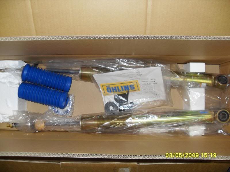

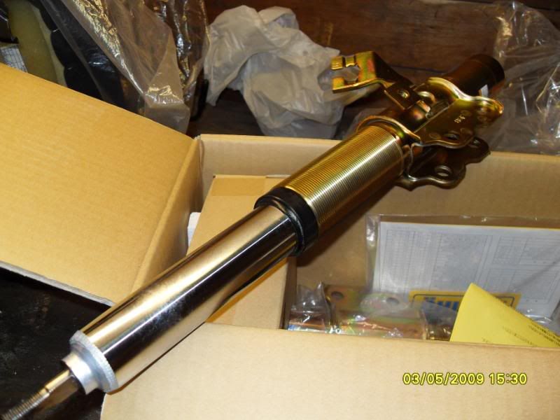
I'm glad that's over.
I've been having a discussion on roll center adjustment and rod-ends for suspension pieces over and zilvia.net. And basically sourcing and building everything myself wouldn't save me a penny over just buying stuff that's already out there. When I priced out aurora bearings for my sway bar end links. Not even using the high-mis-alignment stuff the price came to about $37 per corner.
AW6 3/8_24 female steel rod end $15 x2
Steel jack screw at midwest control products $1.62
Aluminum spacers and grade 8 bolts $5
It turns out mazdaspeed sell the same thing for $39. I ended up just ordering the mazdaspeed ones from goodwin racing to save myself the time of sourcing the spacers, nuts and bolts. I also ordered some extra boot protectors from seals-it that I'm going to fill with some synthetic brake caliper grease just for corrosion protection.
http://www.sealsit.com/rodendboots.asp
Even though the US economy has seen better days, it seams that most the rest of the world is doing a little bit worse. We are doing pretty damn well against both the yen and pound, which makes these a pretty damn good deal:
http://www.driftworks.com/catalog/pr...2-r33-r34.html
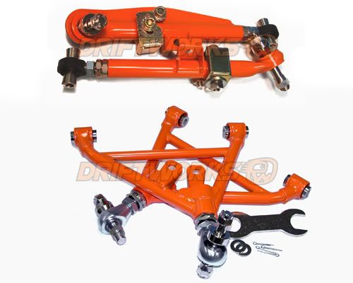
With current exchange rates these come out to about $615 before shipping for all four corners! I'm pretty sure these are what Bill from DSG is running in the front, and these guys have an excellent reputation in Europe. Plus, then you don't have to actually do any work, or make any delrin bearings.


I'm glad that's over.
I've been having a discussion on roll center adjustment and rod-ends for suspension pieces over and zilvia.net. And basically sourcing and building everything myself wouldn't save me a penny over just buying stuff that's already out there. When I priced out aurora bearings for my sway bar end links. Not even using the high-mis-alignment stuff the price came to about $37 per corner.
AW6 3/8_24 female steel rod end $15 x2
Steel jack screw at midwest control products $1.62
Aluminum spacers and grade 8 bolts $5
It turns out mazdaspeed sell the same thing for $39. I ended up just ordering the mazdaspeed ones from goodwin racing to save myself the time of sourcing the spacers, nuts and bolts. I also ordered some extra boot protectors from seals-it that I'm going to fill with some synthetic brake caliper grease just for corrosion protection.
http://www.sealsit.com/rodendboots.asp
Even though the US economy has seen better days, it seams that most the rest of the world is doing a little bit worse. We are doing pretty damn well against both the yen and pound, which makes these a pretty damn good deal:
http://www.driftworks.com/catalog/pr...2-r33-r34.html

With current exchange rates these come out to about $615 before shipping for all four corners! I'm pretty sure these are what Bill from DSG is running in the front, and these guys have an excellent reputation in Europe. Plus, then you don't have to actually do any work, or make any delrin bearings.
#107
Sweet geezus those Ohlins are nice!
__________________
Glenn ***
Sales Tech
www.bmrsuspension.com
813.986.9302

Find a Quality alignment shop near you!
Glenn ***
Sales Tech
www.bmrsuspension.com
813.986.9302

Find a Quality alignment shop near you!
#108
Thread Starter
Joined: Mar 2005
Posts: 624
Likes: 0
From: Trabuco Canyon, CA
I wish I had known about these two weeks ago. They claim to use "High quality, American made, Teflon lined rod ends." Live and learn
http://advanced-autosports.com/PROD0...n_steering.htm
I just picked up the mazdaspeed heim joint endlinks for the miata (and I was hoping to use them on the 240sx as well), but when I got them, I found out that they were made from cheap *** ball ends
http://advanced-autosports.com/PROD0...n_steering.htm
I just picked up the mazdaspeed heim joint endlinks for the miata (and I was hoping to use them on the 240sx as well), but when I got them, I found out that they were made from cheap *** ball ends

#109
Thread Starter
Joined: Mar 2005
Posts: 624
Likes: 0
From: Trabuco Canyon, CA
from post 170
MAX backspace Front~ 150-159mm
MAX backspace Rear~ 172-179mm
When I made these determinations
I was taking advertized wheel widths, deviding by 2, and adding the advertized offset to calculate backspace. As cnichols recently pointed out to me, that only gets you the backspace to the inside of the inner lip! True backspace is to the outside of the wheel, not the inside of the lip that holds the tire.
This picture should help explain:
This is a pic of my rear wheels 17x10.5 +27.
Using my previous calculations would yield a back space of
(10.5x25.4)/2 + 27 = 160.35 mm
which is 13.65mm off from the actual measured backspace of 174mm

So how well does a 174mm backspace 17" wheel fit the rear of an s14?
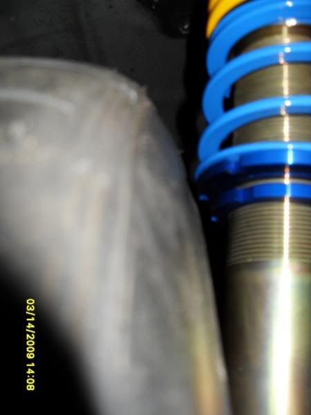
My new Ohlins shock body is 49.7mm in diameter and sits exactly 13mm from the above wheel.
And 22.8mm from the front edge of the lower control arm
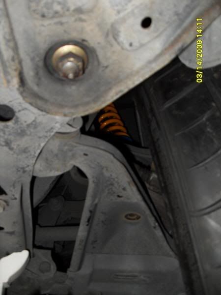
and no clearance issues to the rear

With the coilovers up high no problem
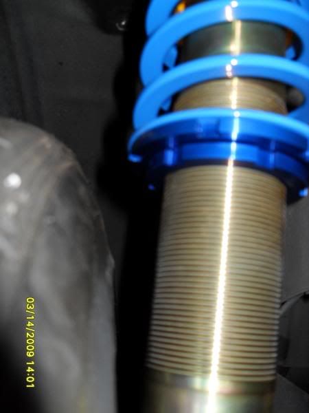
With them low... uh...
sill clears, but...
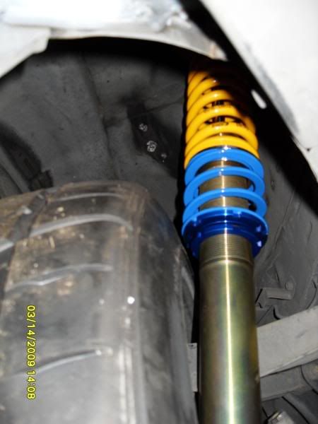
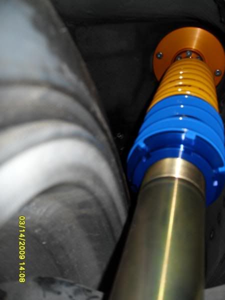
So if you're about to order a new set of custom CCW wheels what backspace to you ask for? Less than 174+13= 187 (7.362")
Max Frontspace with stock fenders: (calculated using my old method)
S13 Front 95-105 (thatguy looks great at 99)
S13 Rear 80-95
S14 Front 109-116
S14 Rear 97-117 (107 really is perfect with a good r+p)
So far I've only done the roll and pull on my drivers side rear fender.
I took this measurement directly below the back edge of the rear window.
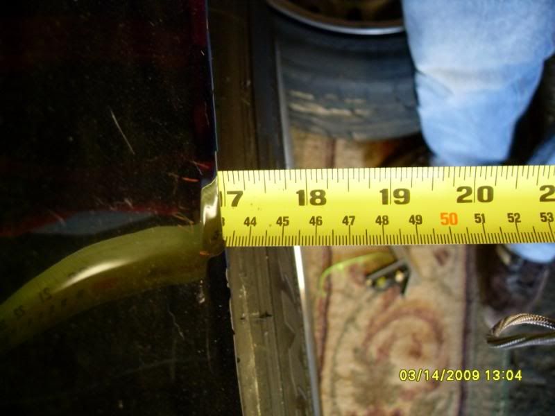
Looks like my R+P gave me an extra 38mm over stock. Presuming both sides have the same depth of well. And It damn near looks stock too!
Stock Passenger Side
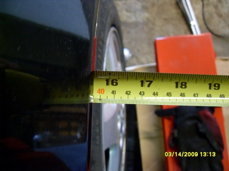
My current front space, from hub face to outer tire edge is
(25.4x10.5)/2 - 27 = 106.35mm
I probably could use a 10mm spacer and still be fine with my fender clearance, but I doubt that I could pull the fender much more without it looking weird.
So lets call it a max frontspace of 115mm and a max backspace (only to the outer tire edge) of 170mm would yield a wheel 285mm (11.22"). If you go any bigger you're going to have to do something drastic to your fenders. Also, to pull this off, your coils will probably have to sit higher than the tire.
I would really like to own the redline time-attack street class some day. The current rules only allow tires upto 285s, and forbid inboard/cantilevered dampers. I think that a 11.22" wheel would be perfect for 285/30/18 tires. Personally I'd order up four of them all with the same <7.362" backspace and just use whatever spacer and fenders are necessary in the front.
This makes me happy.
MAX backspace Front~ 150-159mm
MAX backspace Rear~ 172-179mm
When I made these determinations
I was taking advertized wheel widths, deviding by 2, and adding the advertized offset to calculate backspace. As cnichols recently pointed out to me, that only gets you the backspace to the inside of the inner lip! True backspace is to the outside of the wheel, not the inside of the lip that holds the tire.
This picture should help explain:
This is a pic of my rear wheels 17x10.5 +27.
Using my previous calculations would yield a back space of
(10.5x25.4)/2 + 27 = 160.35 mm
which is 13.65mm off from the actual measured backspace of 174mm

So how well does a 174mm backspace 17" wheel fit the rear of an s14?
My new Ohlins shock body is 49.7mm in diameter and sits exactly 13mm from the above wheel.
And 22.8mm from the front edge of the lower control arm

and no clearance issues to the rear

With the coilovers up high no problem

With them low... uh...
sill clears, but...


So if you're about to order a new set of custom CCW wheels what backspace to you ask for? Less than 174+13= 187 (7.362")
Max Frontspace with stock fenders: (calculated using my old method)
S13 Front 95-105 (thatguy looks great at 99)
S13 Rear 80-95
S14 Front 109-116
S14 Rear 97-117 (107 really is perfect with a good r+p)
So far I've only done the roll and pull on my drivers side rear fender.
I took this measurement directly below the back edge of the rear window.

Looks like my R+P gave me an extra 38mm over stock. Presuming both sides have the same depth of well. And It damn near looks stock too!
Stock Passenger Side

My current front space, from hub face to outer tire edge is
(25.4x10.5)/2 - 27 = 106.35mm
I probably could use a 10mm spacer and still be fine with my fender clearance, but I doubt that I could pull the fender much more without it looking weird.
So lets call it a max frontspace of 115mm and a max backspace (only to the outer tire edge) of 170mm would yield a wheel 285mm (11.22"). If you go any bigger you're going to have to do something drastic to your fenders. Also, to pull this off, your coils will probably have to sit higher than the tire.
I would really like to own the redline time-attack street class some day. The current rules only allow tires upto 285s, and forbid inboard/cantilevered dampers. I think that a 11.22" wheel would be perfect for 285/30/18 tires. Personally I'd order up four of them all with the same <7.362" backspace and just use whatever spacer and fenders are necessary in the front.
This makes me happy.
Last edited by GIGAPUNK; 03-14-2009 at 11:07 PM.
#110
Thread Starter
Joined: Mar 2005
Posts: 624
Likes: 0
From: Trabuco Canyon, CA
I've really been interested in aerodynamics since I was a kid, and have toyed with the idea of having my own aluminum extruded wings made off of existing naca/nasa/sae airfoils. But recently Emelio at 949 racing mentioned in his blog that he had gotten some substantial downforce by combining 3 apr extruded wings into a single compound wing. It turns out APR will even make custom lengths for you! APR has a resaler local to me, http://www.fizzautosports.com/, so I called them to ask if they would let me trace the profiles of any of their apr wings so I could do my own cfd analisys. They were afraid to let me remove the allen bolts holding on the end plates, but gave me apr performance's direct phone number. The help line then gave me their r&d e-mail, saying that they had their own cfd for their 3D carbon wings, but not for their 2D alluminum wings. Here's the e-mail I just sent to their R&D.
I'm building a car for redline time attack and hill climbs. The slower speeds of the hillclimbs, neccesitates a higher Cl than current wing offerings can provide. Current rules limit the dimensions of my wing to a chord of 14" and length of 68", and do not exclude compound wings. An acquantence of mine, Emilio at 949racing, said that he had been able to get some substantial downforce by piecing together 3 of your extruded wings into a compound airfoil. I was wondering if you had and CFD information available on your different, individual aluminum wing profiles, or if you had used any known naca/nasa wing profiles in building your aluminum wings? If so which profiles did you use and at what chord length? If you didn't use known airfoils, will you please forward me some pictures or illustrations of the profiles that you have available including the name you use for ordering, and their chord lengths?
It'll be interesting to see what I get back.
#111
I've really been interested in aerodynamics since I was a kid, and have toyed with the idea of having my own aluminum extruded wings made off of existing naca/nasa/sae airfoils. But recently Emelio at 949 racing mentioned in his blog that he had gotten some substantial downforce by combining 3 apr extruded wings into a single compound wing. It turns out APR will even make custom lengths for you! APR has a resaler local to me, http://www.fizzautosports.com/, so I called them to ask if they would let me trace the profiles of any of their apr wings so I could do my own cfd analisys. They were afraid to let me remove the allen bolts holding on the end plates, but gave me apr performance's direct phone number. The help line then gave me their r&d e-mail, saying that they had their own cfd for their 3D carbon wings, but not for their 2D alluminum wings. Here's the e-mail I just sent to their R&D.
I'm building a car for redline time attack and hill climbs. The slower speeds of the hillclimbs, neccesitates a higher Cl than current wing offerings can provide. Current rules limit the dimensions of my wing to a chord of 14" and length of 68", and do not exclude compound wings. An acquantence of mine, Emilio at 949racing, said that he had been able to get some substantial downforce by piecing together 3 of your extruded wings into a compound airfoil. I was wondering if you had and CFD information available on your different, individual aluminum wing profiles, or if you had used any known naca/nasa wing profiles in building your aluminum wings? If so which profiles did you use and at what chord length? If you didn't use known airfoils, will you please forward me some pictures or illustrations of the profiles that you have available including the name you use for ordering, and their chord lengths?
It'll be interesting to see what I get back.
I'm building a car for redline time attack and hill climbs. The slower speeds of the hillclimbs, neccesitates a higher Cl than current wing offerings can provide. Current rules limit the dimensions of my wing to a chord of 14" and length of 68", and do not exclude compound wings. An acquantence of mine, Emilio at 949racing, said that he had been able to get some substantial downforce by piecing together 3 of your extruded wings into a compound airfoil. I was wondering if you had and CFD information available on your different, individual aluminum wing profiles, or if you had used any known naca/nasa wing profiles in building your aluminum wings? If so which profiles did you use and at what chord length? If you didn't use known airfoils, will you please forward me some pictures or illustrations of the profiles that you have available including the name you use for ordering, and their chord lengths?
It'll be interesting to see what I get back.
#112
Thread Starter
Joined: Mar 2005
Posts: 624
Likes: 0
From: Trabuco Canyon, CA
You can see it here, "Build record for the 949Racing track day project car (the OGK)" on Emelio's blog.
http://949racing.blogspot.com/2009/0...ets-caged.html
"Adding the wing made the car tight, totally overpowering the front downforce provided by the air dam. What's crazy is even at zero angle of attack, I could feel the wing making the car stick better as low as 60mph. Amazing.
The wing is made up of parts from three different models and the minimum rake was like 10°. So I drilled new holes for the stanchions, put some nutserts in and moved the stanchions wider while I was at it. It's mounted to the body outside of the trunk.
So now it needs more front downforce. We'll add a 3" splitter thats sorta squared off on the outside corners. On those corners we'll add dive plane (canards) to help keep air off the front tires. Hopefully that'll balance the car out."
I'm not sure which models it's composed of. It's interesting to note that while it may look like the leading wing is at a negative angle of attack, with a compound wing it is the line formed by leading edge of the first wing and the trailing edge of the last wing that determines the AOA. By using compound wings you can get a much greater effective camber to your your over all airfoil and produce much higher coefficients of lift, without flow separation (aka drag).
#115
Thread Starter
Joined: Mar 2005
Posts: 624
Likes: 0
From: Trabuco Canyon, CA
Builds been on a slight hold while I'm preparing for a liscensing exam. But yesterday I went with my girl to this really nice seafood restaurant here in Long Island. It's finally crested 69 degrees here in the NE, and we took the miata with it's supercharger and Link fuel management computer. The valets were standing there but I just parked my self anyway. And as we were walking into the restaurant they were kinda pushy about getting my keys. So I finally just handed the Dick my keys not wanting to make a scene, for my girls sake. The aftermarket ECU surges a bit, doesn't like light throttle, and requires ~30 seconds of waiting in the accesory position to turn on, prime the fuel pump, and sync the cam and crank angle sensors, before it will let you ignite the engine. We had a great dinner and when we came out instead of getting bent out of shape, I just handed the Dick my valet stub, then told my girl, "Watch this, this is going to be funny." Of course the guy couldn't get it started, my little miata is parked between some $100k Mercedes and Jaguar turning over and over. We both laughed as he came back with his head held low and handed me back my keys with out looking me in the eyes. Then we hopped in the car, and because I waited the requisit time before turning it over, it started instantly. All the valets were watching as it started right up and with a little creative clutching pulled out as though it was dead stock. As I drove past the Dick I said, "There was a reason I didn't want to give you my keys." My girl thought that was a good show.
#117
Thread Starter
Joined: Mar 2005
Posts: 624
Likes: 0
From: Trabuco Canyon, CA
Exhaust Design Time
So I'm starting at the back.
I left my stock s14 fuel tank back in CA when I moved to the East Coast. It's actually a pretty good design and if it was still here I'd probably use it. Most of the stock tanks volume sits above the diff between the rear shock towers, then has two legs that go forward and below the rear seats on either side of the drive shaft.
My idea is to try and get the weight of the tank a bit lower and further back. I also want to build my own rear diffuser. So originally I was thinking of cutting out the bottom of the trunk, and making a custom aluminum tank whose bottom doubled as the majority of the diffuser.
My dad was pointing out that aluminum tanks should probably be rubber mounted to reduce the likelyhood of fatigue cracks which Aluminum is susceptible to. Anyone have any experience with aluminum gas tanks?
So what does a fuel tank have to do with the exhaust? Well with the sides of the drive shaft space open there is extra room for my expansion chamber and cats.
From Random Technologies Website: "...a 3" diameter 7000 series SuperStainless catalytic converter flows 617 cfm. Most 3" diameter high performance mufflers flow less than 475 cfm at the same test pressure."
I also found these test results where 2.5" aftermarket cats were tested and compared to stock LS1 f-body cats.
Table 1
Inlet Diameter (in.)
Outlet Diameter (in.)
CFM @ 20.4” H2O
CFM @ 28” H2O
Passenger Side Catalytic Converter
2.5
2.5
299.5
350.9
Driver's Side Catalytic Converter
2.5
2.5
268.3
314.4
TTS Bullet Catalytic Converter
2.5
2.5
277.1
324.6
Carsound Catalytic Converter
2.5
2.5
372.7
436.7
FLP Catalytic Converter
2.5
2.5
376.0
440.5
First a word on CFM flow rates. Heads are usually flowed at 28” H2O, while carburetors are usually rated at 20.4” H2O, and my hero David Vizard rates exhaust flow CFM at 20.4” H2O. By the looks of things Random Technologies rates their cats at 28” H2O.
But why care about cats on a 700hp v8? Redline time attack street class rules, that's why. Oh and they are way more restrictive than you might think.
David Vizard’s research shows that 2.2 cfm of flow at 20.4” of H2O will support 1 horsepower. 2.2 cfm is the optimum flow through the exhaust keeps horsepower losses under one percent.1 Removing the stock catalytic converters on the LS1 usually results in a gain of 8 rear wheel horsepower.
FLP or Carsound = 373cfm
373/2.2= 170 hp per cat (w/ 2.5” i/o)
Random Technology 3" diameter 7000 = 617 cfm (probably 524 cfm @ 20.5" H20)
524/2.2= 238 hp per cat
Now it should be a little more clear.
If you're rolling a single cat, you have a restriction if you're making over 170-240hp, regardless of which fancy pants stainless "race" cat you're running! Bogus!
This also means that if I'm running FLP aftermarket race cats that I would need 4 (3 if I ran the randoms) of them in parallel to build a truely free flowing exhaust! I've never seen anyone run cats in parallel. The reason for this is either cost, space, or you can't get enough heat into them. I dunno.
To make sure that street class participants aren't running gutted cats, redline states that they will use infraread thermometers to make sure that your cats are lighting off.
more from random technologies web site: "...Under normal operating conditions, the catalytic process doesn’t begin until temperatures inside a converter reach 500 to 600 degrees (F). If air/fuel ratio is on target, and the exhaust is free of contaminants, internal converter temperature stays at about 1200 degrees. But when unburned fuel enters the picture, temperatures can reach 2200 degrees and either burn the precious metals out of the washcoat, or literally cause a melt down of the bricks."
So now the real question is: will three or four parallel cats get up to temperature if they are sitting five feet from the heads with an expansion chamber between them? By definition anything richer than 14.7 will have "unburned fuel". And considering my car will be running richer than 13:1 most of the time, maybe the extra exhaust temps will actually be useful? Redline doesn't say when them test your cats temps. I'm pretty sure I'd be ok after a hot run.
This is getting too long, but here are some pics of preliminary measurements for the rear diffuser/new fuel tank area, and I'll talk about expansion chamber design another day.
This is a pic of a one inch piece of steel stuck to the bottom of the subframe. The piece of steel creates two rectangular spaces about 3"x5" on either side of the diff. Should be enough for four 2.5" exhaust pipes.
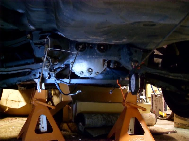
would four 2.5" exhaust pipes flow enough for 700hp?
Check this out:
A section of straight pipe the length of a typical muffler, rated at the same test pressure as a carb (1.5” of mercury= 20.4” H2O), flows about 115 cfm per square inch.
open horsepower
pipe supported w/
size single pipe
2.0” D = 3.1 A X 155/2.2 = 218 HP (x4=872 HP, probably a better idea)
2.5” D = 4.9 A X 155/2.2 = 345 HP (x4=1380 HP, yeah should be ok)
3.0” D = 7.1 A X 155/2.2 = 500 HP
3.5” D = 9.6 A X 155/2.2 = 676 HP
4.0” D = 12.6 A X 155/2.2 = 887 HP (Proof Hondas with 4" mufflers are built by ********)
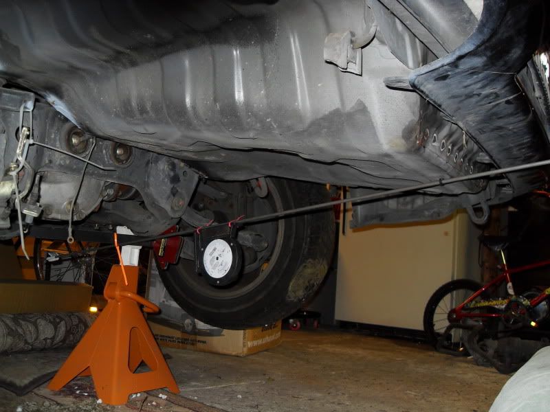

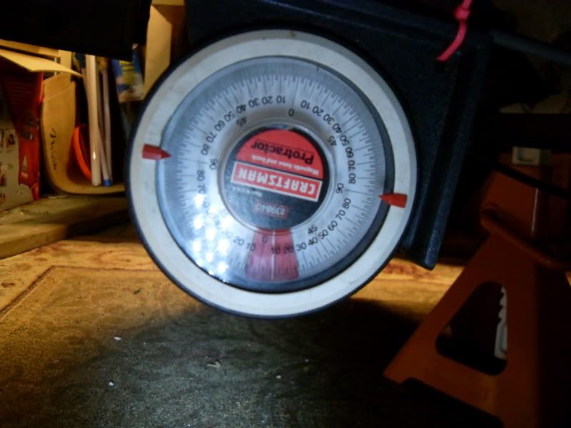
It seems that diffusers can sit anywhere from 4-14 degrees. Less than 7 degrees to prevent flow seperation/drag unless of course you have a massive wing within a verticle foot for interaction like F1.
So I'm starting at the back.
I left my stock s14 fuel tank back in CA when I moved to the East Coast. It's actually a pretty good design and if it was still here I'd probably use it. Most of the stock tanks volume sits above the diff between the rear shock towers, then has two legs that go forward and below the rear seats on either side of the drive shaft.
My idea is to try and get the weight of the tank a bit lower and further back. I also want to build my own rear diffuser. So originally I was thinking of cutting out the bottom of the trunk, and making a custom aluminum tank whose bottom doubled as the majority of the diffuser.
My dad was pointing out that aluminum tanks should probably be rubber mounted to reduce the likelyhood of fatigue cracks which Aluminum is susceptible to. Anyone have any experience with aluminum gas tanks?
So what does a fuel tank have to do with the exhaust? Well with the sides of the drive shaft space open there is extra room for my expansion chamber and cats.
From Random Technologies Website: "...a 3" diameter 7000 series SuperStainless catalytic converter flows 617 cfm. Most 3" diameter high performance mufflers flow less than 475 cfm at the same test pressure."
I also found these test results where 2.5" aftermarket cats were tested and compared to stock LS1 f-body cats.
Table 1
Inlet Diameter (in.)
Outlet Diameter (in.)
CFM @ 20.4” H2O
CFM @ 28” H2O
Passenger Side Catalytic Converter
2.5
2.5
299.5
350.9
Driver's Side Catalytic Converter
2.5
2.5
268.3
314.4
TTS Bullet Catalytic Converter
2.5
2.5
277.1
324.6
Carsound Catalytic Converter
2.5
2.5
372.7
436.7
FLP Catalytic Converter
2.5
2.5
376.0
440.5
First a word on CFM flow rates. Heads are usually flowed at 28” H2O, while carburetors are usually rated at 20.4” H2O, and my hero David Vizard rates exhaust flow CFM at 20.4” H2O. By the looks of things Random Technologies rates their cats at 28” H2O.
But why care about cats on a 700hp v8? Redline time attack street class rules, that's why. Oh and they are way more restrictive than you might think.
David Vizard’s research shows that 2.2 cfm of flow at 20.4” of H2O will support 1 horsepower. 2.2 cfm is the optimum flow through the exhaust keeps horsepower losses under one percent.1 Removing the stock catalytic converters on the LS1 usually results in a gain of 8 rear wheel horsepower.
FLP or Carsound = 373cfm
373/2.2= 170 hp per cat (w/ 2.5” i/o)
Random Technology 3" diameter 7000 = 617 cfm (probably 524 cfm @ 20.5" H20)
524/2.2= 238 hp per cat
Now it should be a little more clear.
If you're rolling a single cat, you have a restriction if you're making over 170-240hp, regardless of which fancy pants stainless "race" cat you're running! Bogus!
This also means that if I'm running FLP aftermarket race cats that I would need 4 (3 if I ran the randoms) of them in parallel to build a truely free flowing exhaust! I've never seen anyone run cats in parallel. The reason for this is either cost, space, or you can't get enough heat into them. I dunno.
To make sure that street class participants aren't running gutted cats, redline states that they will use infraread thermometers to make sure that your cats are lighting off.
more from random technologies web site: "...Under normal operating conditions, the catalytic process doesn’t begin until temperatures inside a converter reach 500 to 600 degrees (F). If air/fuel ratio is on target, and the exhaust is free of contaminants, internal converter temperature stays at about 1200 degrees. But when unburned fuel enters the picture, temperatures can reach 2200 degrees and either burn the precious metals out of the washcoat, or literally cause a melt down of the bricks."
So now the real question is: will three or four parallel cats get up to temperature if they are sitting five feet from the heads with an expansion chamber between them? By definition anything richer than 14.7 will have "unburned fuel". And considering my car will be running richer than 13:1 most of the time, maybe the extra exhaust temps will actually be useful? Redline doesn't say when them test your cats temps. I'm pretty sure I'd be ok after a hot run.
This is getting too long, but here are some pics of preliminary measurements for the rear diffuser/new fuel tank area, and I'll talk about expansion chamber design another day.
This is a pic of a one inch piece of steel stuck to the bottom of the subframe. The piece of steel creates two rectangular spaces about 3"x5" on either side of the diff. Should be enough for four 2.5" exhaust pipes.

would four 2.5" exhaust pipes flow enough for 700hp?
Check this out:
A section of straight pipe the length of a typical muffler, rated at the same test pressure as a carb (1.5” of mercury= 20.4” H2O), flows about 115 cfm per square inch.
open horsepower
pipe supported w/
size single pipe
2.0” D = 3.1 A X 155/2.2 = 218 HP (x4=872 HP, probably a better idea)
2.5” D = 4.9 A X 155/2.2 = 345 HP (x4=1380 HP, yeah should be ok)
3.0” D = 7.1 A X 155/2.2 = 500 HP
3.5” D = 9.6 A X 155/2.2 = 676 HP
4.0” D = 12.6 A X 155/2.2 = 887 HP (Proof Hondas with 4" mufflers are built by ********)


It seems that diffusers can sit anywhere from 4-14 degrees. Less than 7 degrees to prevent flow seperation/drag unless of course you have a massive wing within a verticle foot for interaction like F1.
#118
Thread Starter
Joined: Mar 2005
Posts: 624
Likes: 0
From: Trabuco Canyon, CA
So I just took a look at the revised 2009 Redline time attack rule book and it looks like full undertrays are now allowed in street class. The wording on the fuel cell rules is a little strange:
"1.6.4 Fuel Cells permitted (modification of factory floor pan is allowed for installation of
Fuel Cell)
1.6.4.1 Good quality fuel cells contain a bladder constructed of Nylon or Dacron
woven fabric impregnated and coated with a fuel resistant elastomer and
are FIA FT-3 (or higher) rated.
1.6.4.2 The cell should be in a container made of at least 0.036-inch steel, 0.059-inch
aluminum, or 0.125-inch Marlex, fully surrounding the bladder.
1.6.4.3 Foam internal baffling is required, as per FIA FT3-1999 (or higher)."
So it says that fuel cells are permitted, then it goes on to define a good one as one with a bladder. It doesn't seem to expressly require a bladder within the cell though. The rules also seem to say that there "should" be a container for the bladder. Does should = required? Or am I just seeing what I want?
Bladders are around a $1000. I was hoping to get the car on the road without one, with just a custom aluminum fuel tank, then add a custom bladder to it way down the line.
How do you guys interpret the above?
#120
Thread Starter
Joined: Mar 2005
Posts: 624
Likes: 0
From: Trabuco Canyon, CA
Went out to the East coast drift bash at Englishtown, in NJ yesterday. Miro's LS1 powered, pink s13 sounded bitchin with the side pipes. You could tell he was running from the pit entrance, it was so unique. Met up with some friends and we caravan'd it back to NY. One of the guys with us had a super clean rb25 powered s14 running a new garett gt30 at a lowish 14psi. He had been checking out the supercharger on the miata and wanted to race on the parkway. It was a dead lock! I couldn't believe it. If I was in 3rd I'd very slowly pull away, at the end of 4th he'd start to very slowly pull away. We must of gone 4 times, and everytime I'd wait till I heard him spool before punching it. I'm still floored... But happy!
I graduate med school in 2 weeks and just got my passing results for my last licensing exam for a while! So now it's time to play again. Ain't got no money, but small projects will commence! Already started organizin the garage. Stay tuned!
Any one have any pics of soft mounted Aluminum tanks?
And Jordan I'm fairly certain that it's impossible for a door slamm'n coupe to get the rear wing low enough to effect a rear diffuser to the point that any more than 7 degrees is just going to yield drag and no more effective down force. Plus Much more than 9 degrees and you're going to have to cut the trunk.


