When you click on links to various merchants on this site and make a purchase, this can result in this site earning a commission. Affiliate programs and affiliations include, but are not limited to, the eBay Partner Network.
So I got it out for a test drive last night, from the garage straight across town 40mins to my apartment.. runs nice with no leaks or detrimental issues! The wastegates appear to be limiting boost down to 0-1psi up to 4500rpm which is the highest I revved it.. I really just babied it and tried to get a good learn on the base tune for idle up to 3500rpm during part throttle cruising.
The alternator pulley squeals like a pig some of the time it's under load, but not always. The spring tensioner is just dancing all over the place when this happens, so I'm going to try a solid/adjustable tensioner and see how that helps it. I knew this was a risk going into the alternator relocation design, but was hoping it just wouldn't manifest itself.... we'll see how the solid tensioner improves things.
Congrats Joe! I'll bet that felt great! So good to see your car out in the wild again especially with those snazzy new rocket boosters out back. One hell of a beast - hope you get lots of driving in before the season winds down.
Congrats Joe! I'll bet that felt great! So good to see your car out in the wild again especially with those snazzy new rocket boosters out back. One hell of a beast - hope you get lots of driving in before the season winds down.
Thanks! Supposed to be dry and sunny tomorrow so I'll probably get a bit more driving in, but I won't be romping on it too hard until I install the Katech solid/adjustable tensioner I ordered last night. I thought about designing my own lead-screw style tensioner instead of the common slot-and-bolt style, but just decided to buy one that already exists for the time being.
I'm already mentally planning my own shifter that can produce somewhere between the stock T56 shifter throw and the much-shorter McLeod short shifter throw.... I have a problem!
Awesome! 40 minute test drive... you are more brave than I am! Good work
Haha I was originally wanting to have a full weekend day free to test things out close to the garage, but life and weather came in and I decided "screw it, I'm just going to try to drive it home after work one day before it gets dark".
Originally Posted by ryeguy2006a
Congrats on the first test drive! Does that mean that the turbo leak has fixed itself?
It appears so... my thinking is that I had forgotten to fully tighten the turbine housings on both turbos other than 1 or 2 bolts in order to make re-clocking easier during fabrication, so I guess after the turbo sitting there a little bit of oil had leaked out (but not enough to actually drip down) and that little bit was what was burning off.
I'm currently working on modifying my McLeod shifter to work on the retro-tailhousing Magnum.. I'll update with some pics later showing the mods I've done to open up the shifter range as well as tighten up the slop that it came with.
I realized that I've never really uploaded any interior pics, and it was nice and sunny today so I thought I'd snap a few.
I'm still using the stock F-body T56 shifter as I continue modifying and tweaking the McLeod short shift unit.
Briefly in other news, I finally went back and looked at my log from the initial drive home.. it's very interesting that ambient temperature was in the low-60's Fahrenheit, and compressor-output air temp ranged from low-80's up to 115*F.. yet the IAT at the throttlebody was always hovering between 64-69*F. Very interesting how consistent the IAT was, as I know the ambient was pretty cool and I wasn't getting close to boost, but it's nice to see an indication of a pretty efficient intercooler, from those numbers barely varying... hopefully there's lots of thermal capacity left once I get into boost during the summertime!
Been driving the car around a bunch during the dry days this past October..
The main issue I'm dealing with right now is fuel pressure dropoff for no logical reason. When I'm starting at 2500-3000rpm and slowly climb with constant throttle, the fuel pressure, the fuel pressure drops thru the floor.
I've tested:
- tank full of gas, so fuel starvation into the pumps can't be it
- both in-tank pumps *sound* like they're on (from my tuned hearing, sounds louder than just a single pump running).. however I still need to climb under the car and test-hotwire each individual pump to ensure they're both running
- test pull with FPR connected to manifold pressure
- test pull without FPR connected to manifold pressure
My thoughts so far:
- drop in fuel pressure isn't due to some strange action of the FPR influenced by a weird vacuum/boost signal
- even if only a single pump is running, a 6L engine @ 3000rpm not in WOT condition should easily be fed by a single 300lph pump without the pump being a limiter
- I have a Summit brand fuel filter that hasn't been inspected or replaced since installed in the original single turbo setup circa ~2011.... maybe filter is causing restriction and hampering fuel flow
- since I changed from a semi-dead-head fuel rail setup (with FPR before the rails), maybe with full volume of flow running into FPR it is somehow overrunning the FPR spring... doubtful?
- I want to test fuel pressure before and after rails with existings FPR-after-rails setup to see what the pressure differential is due to the rails... not sure what this would tell me other than a point of curiousity
- I want to temporarily re-plumb the rails to be like the old setup, with FPR before the rails and fuel flow thru the rails "dead-headed" and not "thru-flow"... this would simply be a comparison to the old "working" setup
Here are two datalog screengrabs:
This one shows the fuel pressure (faint yellow line) climbing in stages as the MAP goes up, with the FPR connected to the intake manifold. The fuel pressure starts dropping JUST before the calculated fuel flow starts ramping up to compensate...
This datalog shows the fuel pressure slowly falling as the engine RPM's increase at a steady rate, to the point that the fuel flow can't sustain and the fuel pressure drops off...
The fuel pressure sender is located right at the fitting entering the FPR, on the hose returning from the second fuel rail.
So:
1) -8AN from gas tank to back of right bank fuel rail
2) -8AN fittings on fuel rails, -8AN crossover from right to left rail
3) -8AN line from back of left fuel rail to fuel pressure sender T fitting on "intake" side of FPR
4) "output" side of FPR is blocked off, so the only other fitting on the FPR is a -6AN return line back to the tank
Maybe I plumbed the FPR incorrectly, but at the time the above fuel routing made sense.
As a future improvement, I'm contemplating changing the setup to have the FPR before the rails, and split the output of the FPR into two lines each feeding a single rail in parallel, then one end of each rail will be blocked off. This way the pressure differential for supplied fuel would only be across 4 injectors and not all 8 injectors as my current and my previous (FPR before rails) setup were like. This idea was previously posted in my thread by someone, but I had already plumbed my fuel as it currently is at the time.
I'm using an Edelbrock boost-referenced adjustable fuel pressure regulator, -10AN straight cut o-ring threads on the input and output, -6AN return port... so flow restriction in the unit itself shouldn't be an issue.
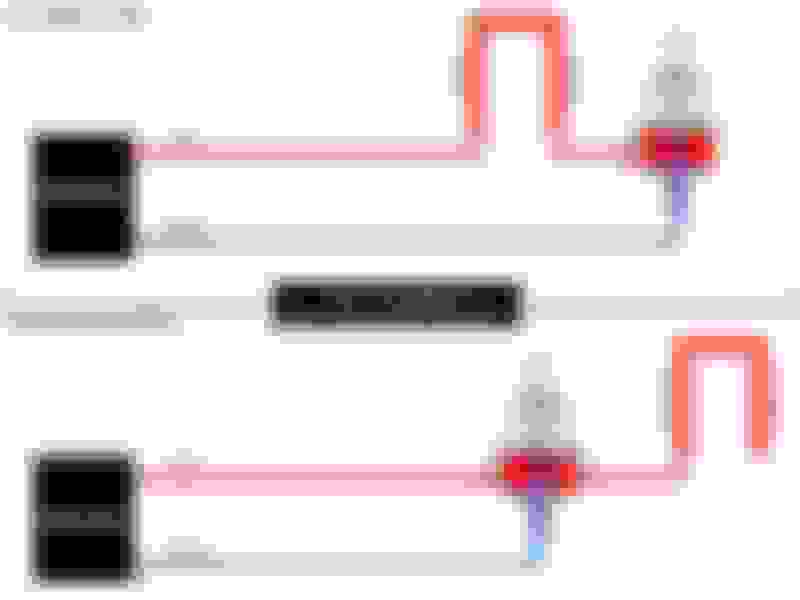
To save myself explaining it via typing... in the below picture my current system is the top diagram, and the bottom diagram was what I had before. The 3rd port is blocked off on my current setup, like the top diagram..
I don't think you can take a forward pressure regulator like that and convert it to a back pressure regulator simply by capping the outlet. Is that how Edelbrock designed it to work? From the Edelbrock instructions it seems to be setup for forward pressure regulation i.e. dead head. With the way its plumbed I wonder if it's bypassing due to trapped pressure on the capped outlet side


 10-04-2018 | 09:28 PM