When you click on links to various merchants on this site and make a purchase, this can result in this site earning a commission. Affiliate programs and affiliations include, but are not limited to, the eBay Partner Network.
We've got socket cap screws in all SAE sizes at work, which I found out are rated to 180 ksi.
What's the PN on that C&R radiator, and does it come with the upper inlet? I'm likely upgrading mine soon in an attempt to battle the 45+� summer heat.
And the upper outlet is a -20 o-ring port thread, I guess to make the rad more universal/flexible for more applications. I got a 1.5" inlet, P/N 78-00104
I'll let you know how much of the rad support needs to be cut away to allow airflow for the 28" wide core, possibly after this weekend if I'm productive.
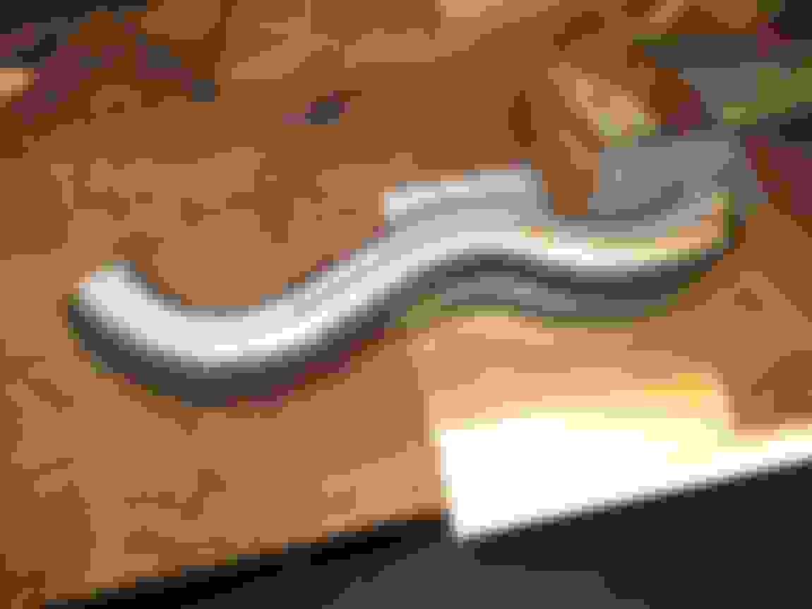
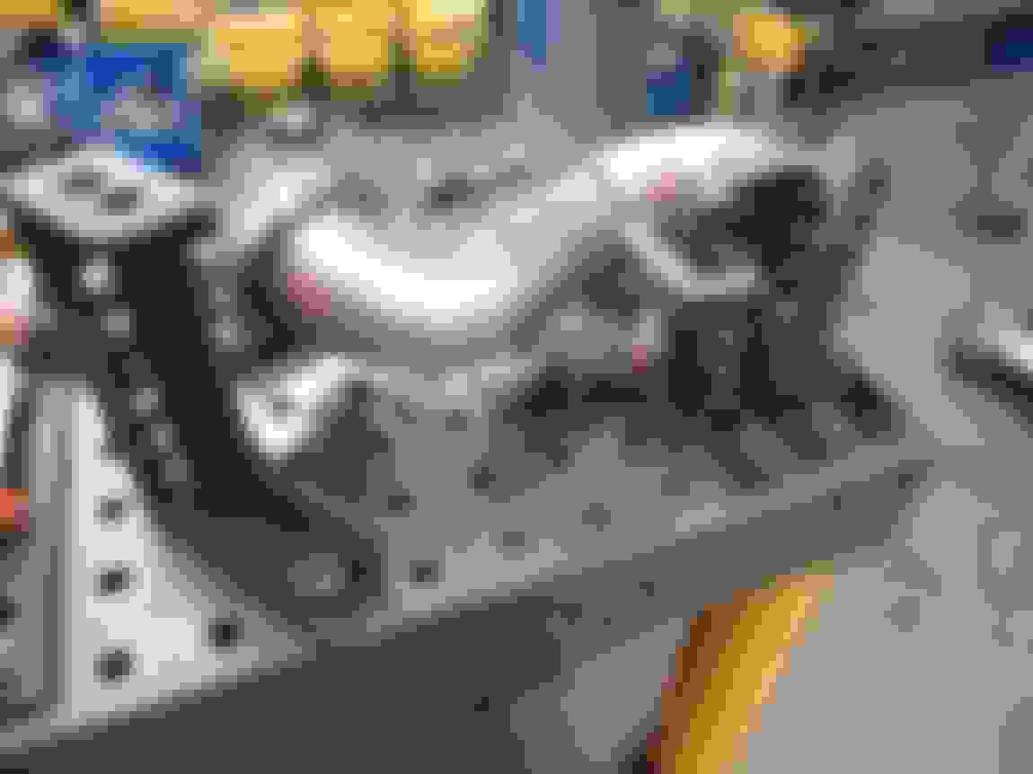
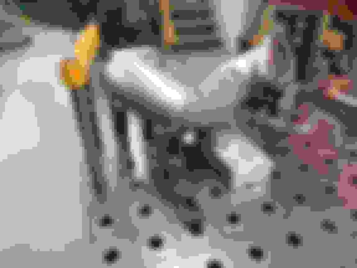
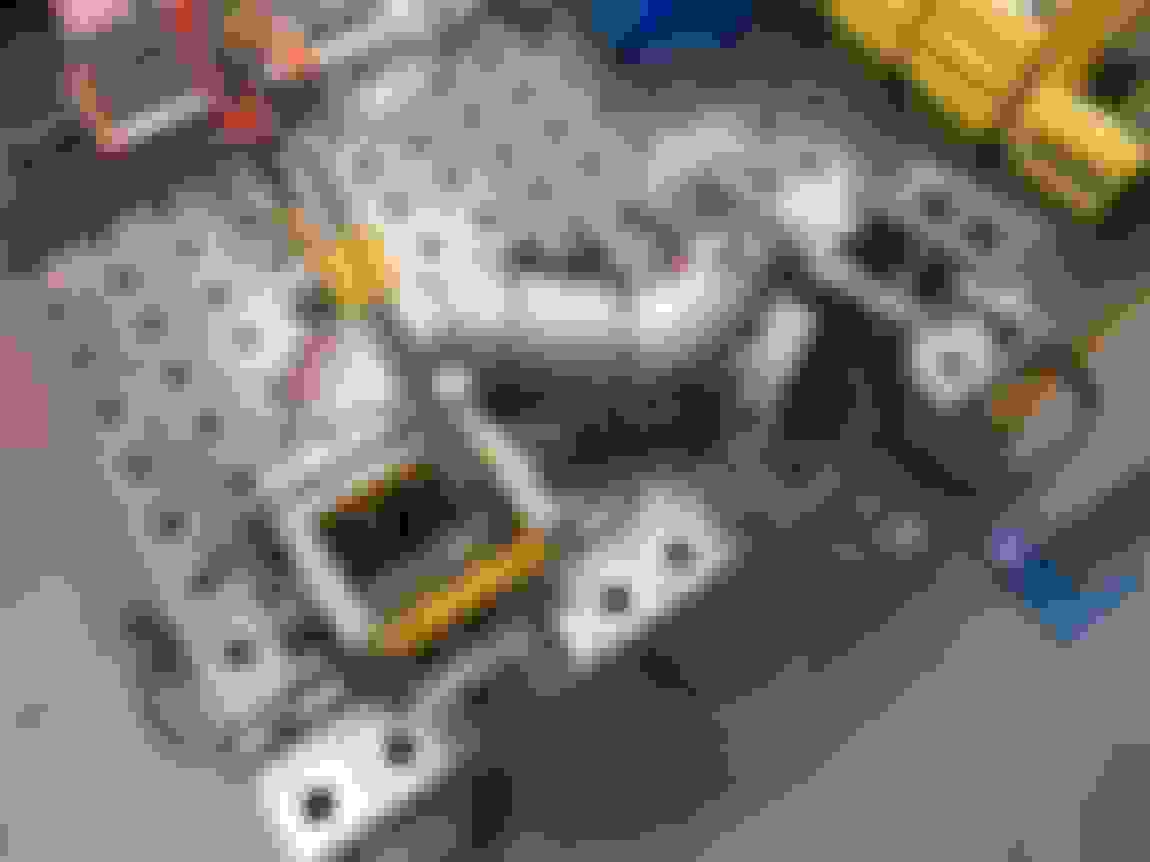
Made some aluminum sleeves to better locate the 1/2" holes on the hotside flanges to the M10 bolts required by the CTS-V exhaust manifold flanges..
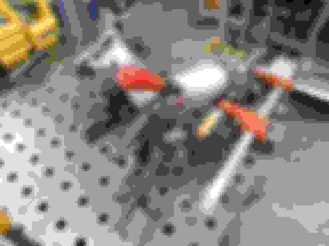
Also cut off the driver side wastegate feed tube and adjusted it to make the angle a bit larger, to raise the driver side wastegate to better mirror the passenger side.
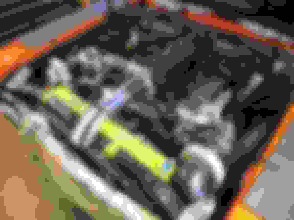
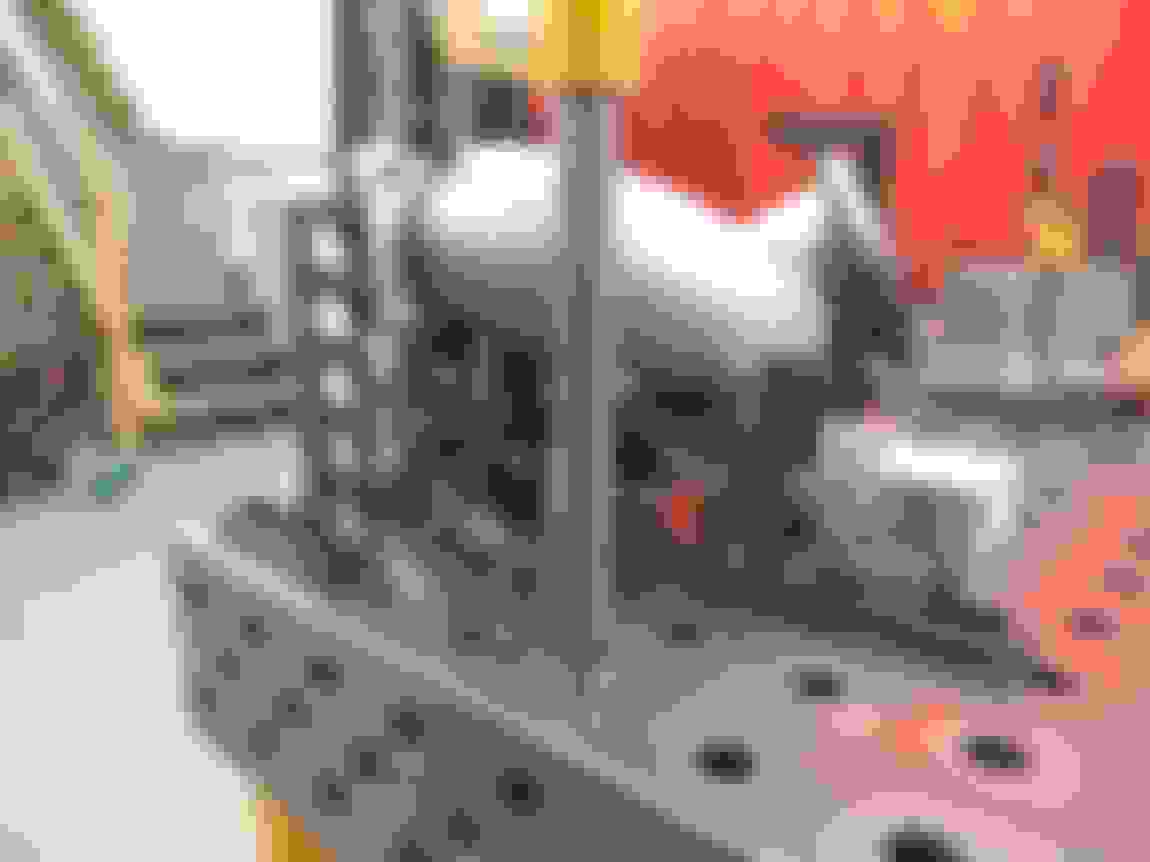
Also mocked up the Precision 64mm BOV just to see where/how it would fit since it's so huge. I think on the passenger side looks actually okay, matches the look of the DBW throttlebody servo. With the BOV on the passenger side it also helps fill some of the void on the passenger side, since I've made everything symmetric but the symmetry plane isn't actually in the middle of the engine. Look at the pre-turbo piping relative to the heads. The turbo's themselves are perfectly symmetric to the engine and their respective piping ended up looking visually correct and not wonky, but it just happened to not be perfectly symmetric to the engine.. oh well.
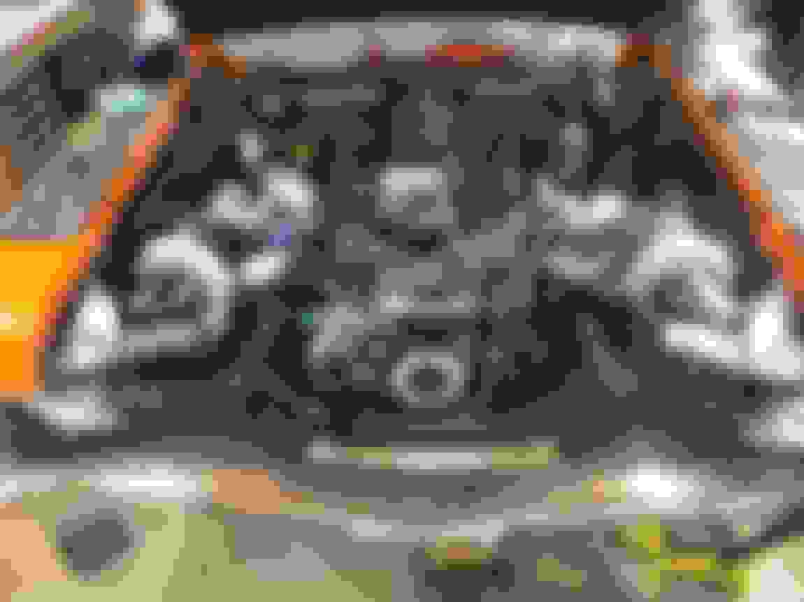
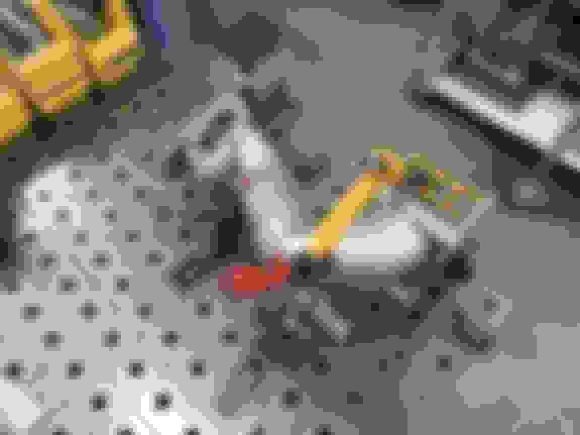
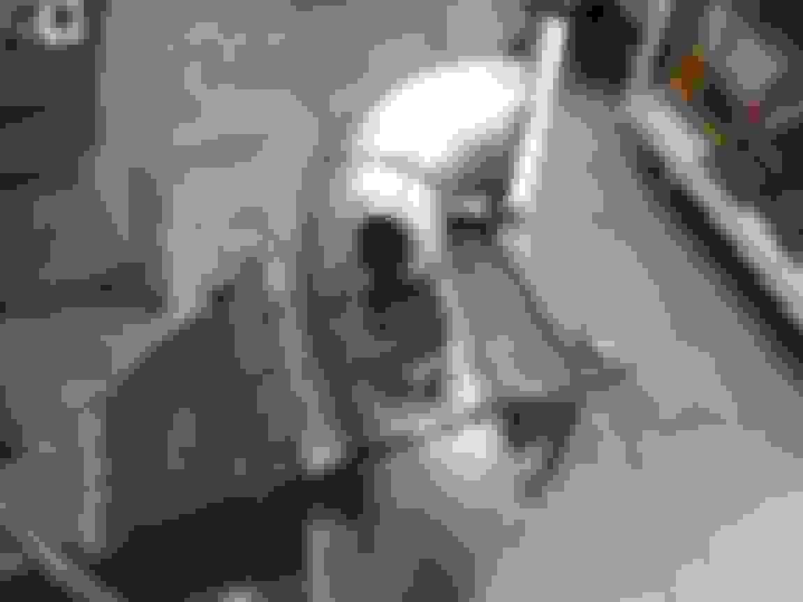
Didn't get too far on disassembling the front end. Not at the point of being able to make a cardboard mockup intercooler, but did enough to start mulling over the piping etc in my head.
Might be hard to see the silver lines on the rad support, but that's how wide I'm going to start trimming the core support. It'll be 1/2" wider than the intercooler on both sides, which will let me jam the intercooler close to the radiator but not touching, and the rad support will be completely outside of the intercooler. I think I'll use some rubber insulation of some type to seal the backside of the intercooler to the front side of the radiator but not allow heat transfer from radiator to intercooler.
Up here in BC we have a 3-day long weekend coming up in a couple days, I have a full tank of Argon, and on Thursday I'll FINALLY be picking up the Precision T3 flanges and downpipe clamps/flanges.. so I could very well have the hotside and a decent amount of the donwpipes finalized this weekend.
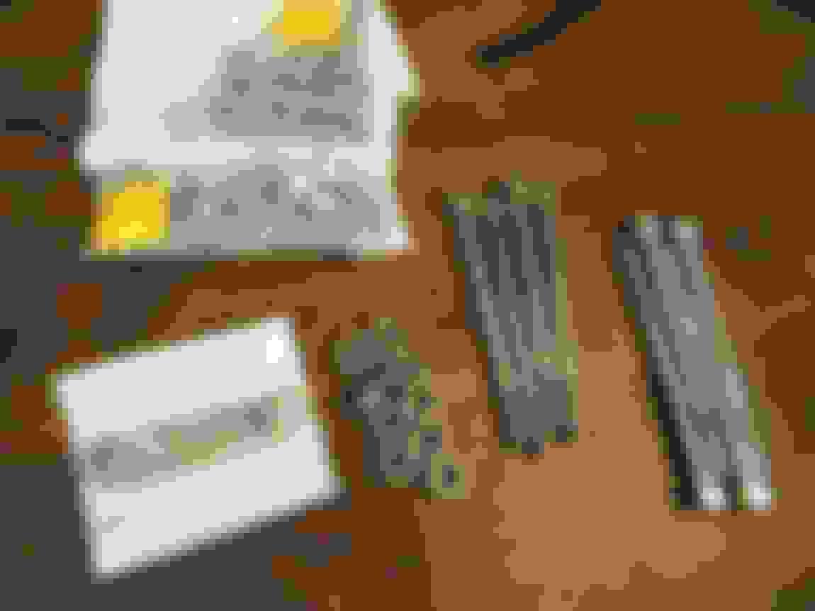
Received the Precision turbine outlet flanges and the T3 inlet flanges. Inlet flanges fit the turbine housing profile much better, slight discrepancy but I'm not going to lose sleep over it.. much better fit than the generic Ace Race Parts T3 flanges which had almost a 3/16" step difference between the T3 flange and the T3 inlet profile on the turbine housing.
Ordered some extra misc M10 flange hex head for various accessory drive stuff, including some SS316 nuts to finish off the stainless turbo mounting hardware.
Turned down the flange OD on the ARP bolts (modified on left, untouched on right) just to have a bit more clearance to the radius on the turbine housing.
Started on the downpipe fabrication, started on the passenger side because the design is much more felxible and I was a bit too hungover to think hard haha.
Downpipes will be 3.0" from the turbo to the subframe rail, then 3.5" under the floorpan back to the rear bumper. This is because the downpipe routing is so tight on the driver side around the steering box that I just didn't want to push it with 3.5" OD and the required increase in centerline bend raidus of the 3.5" 90* bends I have.
I figure that if I am pushing the setup hard enough for the 3.5" dual exhaust to be a significant benefit over full 3.0", then surely having the majority of the exhaust be 3.5" should be enough. The turbo outlets are 3.0" vband but the actual ID of the turbine outlet was something like 2.7" I think when I measured it with calipers.. so 3.0" downpipes for first ~24" shouldn't be a huge deal.
Sure I could've made the passenger downpipe out of minimal bends and a long straight, but I added some style to it because it will be much more visible than the driver side. I tried to make the very front bend mimic the bend of the pre-turbo hot piping, and then make the rest of the downpipe parallel to the slant in the CTS-V manifold. Then have the bend going down to the framerail mimic the bend at the back of the exhaust manifold.. kindof making the downpipe look like a nested duplicate shape of the manifold+hotpiping.
Turning out really nice. Great fitment and routing. You sure don't have a lot of room to work all that plumbing in, but somehow you're making it fit. Bravo
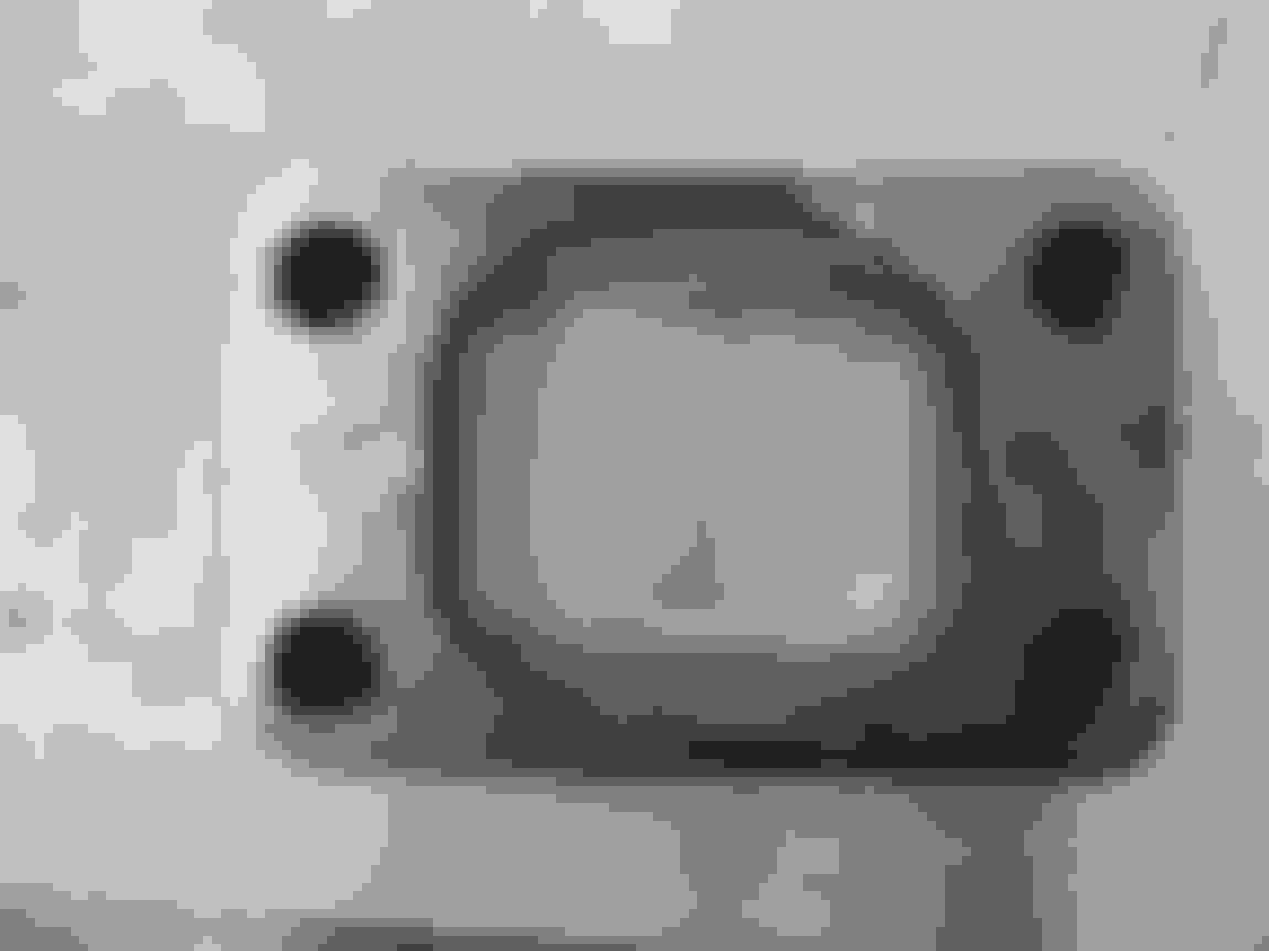
Starting working over the Precision T3 flanges, luckily they are identical in outer profile to the generic ones I had used for mockup.
Here is the difference in rectangular profile between the old (generic) one on top of the Precision one. It was a big enough difference to make me want to swap out, plus the Precision flanges have nice 10mm holes like the turbine housing, the generic flanges had 7/16" holes creating a lot of mounting slop.
A carbide bit on a pneumatic die grinder makes very quick work of the SS304.
Because the new and old flanges are same in outer profile, I used the piping as-is to create a locating setup on the Bluco modular jig at work. We use this jig table for absolutely everything because it's just so easy and awesome. This setup will locate the Precision flanges in the same place as the mockup flanges, to remove any placement error when cut off the old ones.
New Precision flange in place on the driver side hotpipe, right were it's supposed to be.
Setup for the passenger side hotpiping. Using plenty of clamps, height blocks, and locating angle brackets allows the hotpiping to just "click" into place in only one orientation...
And new Precision flange properly located on the passenger flange...
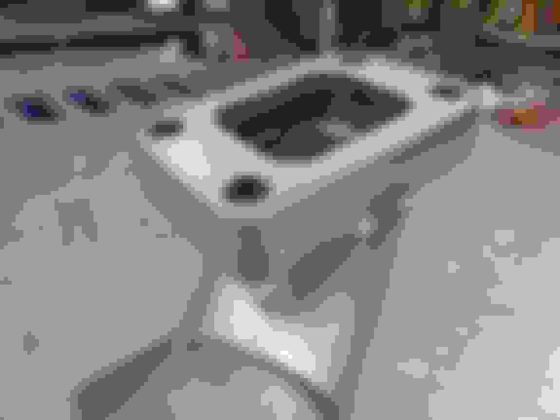
Then I got started on hogging out the hotpiping where the wastegate branches are located.
First step was to use the Scotchbrite buffing wheel to remove all my previous marker lines and start fresh.. mark a nice tight profile line and then a couple locating lines for alignment, then buzz off the tack welds...
Then I marked off the inner area that needed to be removed, constantly checking for accuracy by test placing the wastegate branch in place.
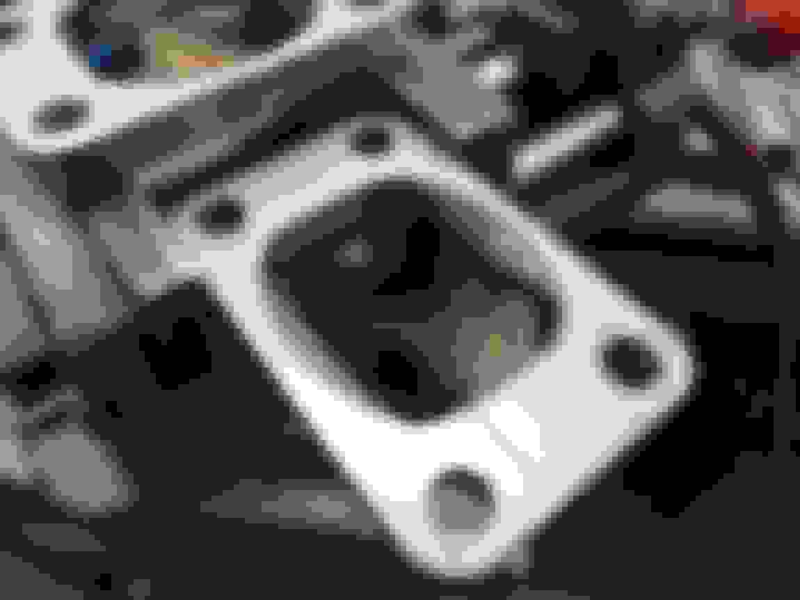
Holesaw for bulk material removal! As a first attempt I realize the holesaw could have been a bit lower down to lessen the amount of rounding/grinding needed to achieve the finished profile, oh well...
Then using a belt sander, cutoff zip wheel, carbide grinding bit, and a file, we have a large smooth opening.
Close enough for my liking... so much flow!
Learned for round 2.. holesaw'd much closer to the finished profile...
More cutting/grinding/smoothing....
Again this jigging table is immensely helpful for quickly holding a weirdly shaped piece on top of another weird shape, so it doesn't annoyingly move around while tack welding in place.


 01-25-2018, 11:24 AM