When you click on links to various merchants on this site and make a purchase, this can result in this site earning a commission. Affiliate programs and affiliations include, but are not limited to, the eBay Partner Network.
I had the frame of my XS650 done in a textured charcoal/black powder coat, which turned out very well. And after powder coating all of my bike parts in my garage (including wheel hoops in a homemade oven), I can't go back to rattle can for the small stuff.
Prismatic powders has a ridiculous selection, and offers free swatches to nail the color prior to purchase. I use an electric Craftsman gun ($50 refurb from eBay) and small oven to do all of my work, with a rack to hang parts in a corner of the garage. It also helps to have access to a bead blaster.
Well that's an enviable setup! I really wish I had the room for an extra oven.. but home powder coating as well as home anodizing has definitely crossed my mind multiple times!
Returned the "gold blade" 2009+ LS3 throttlebody to Summit and ordered a "silver blade" 2005-2008 LS2 throttlebody from Rock Auto. Didn't think the size would be that different between the 90mm 4-bolt TB and the old 78mm 3-bolt truck TB. Pretty interesting to compare side-to-side.. I can't help but think that the increase in size will help even just slightly for transient response etc before "teh boosts" kick in....
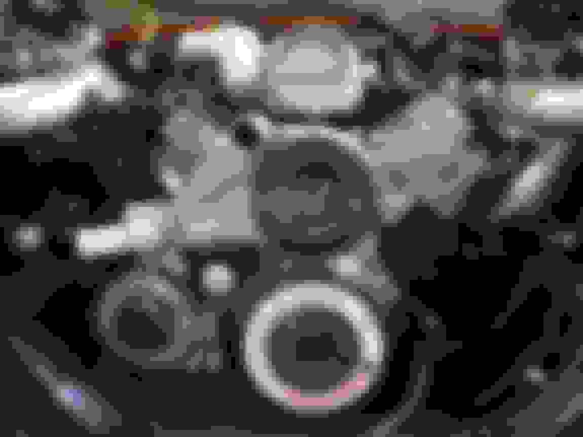
Also ordered a new waterpump. I wanted a waterpump with a wider pulley, so I could set back the pump body itself (for several reasons I'll disclose later) yet maintain the truck belt alignment.
I originally tried an LS2 water pump with the huge dome-like pulley, but it was a repop ACDelco part number that was absolutely **** in build quality. "Made in China" (I try to not let that affect my evaluation) but the heater hose barbs were pressed in at whacky angles, the pulley wobbled, the block-mounting surfaces weren't parallel.. and the killer was that the thermostat housing part of the body was too bulky/low and interfered with my low-mount alternator bracket.
I also returned the **** ACDelco repro early LS2 waterpump and sought out a legit GM 2005-2008 Corvette LS2 waterpump, which has a short nose pump shaft but a wider width pulley to allow it to be used on the compact Corvette LS2 accessory drive alignment or the mid-compact GTO LS2 accessory alignment.
Here's the 1/2" extra length that the 2005-2008 LS2 waterpump pulley has on the 2009+ LS3 pump.
Naturally when you have a brand new part that you're *pretty sure* will fit, you hack it up. This was to shorten the outlet neck to make the rubber rad hose that I already have fit..
Pretty convenient that I found two pre-cut bits from my box of rad hoses that fit the dimensions perfectly...
And started arranging the 3.5" piping to where the intercooler will be. This pic is kinda funny, shows why I was worried the single middle charge pipe will look like an "elephant trunk" haha..
I don't know why they make that water pump nipple so darn long. Everything is nice and tucked to the engine and then they stick that thing out 4 inches. It was begging to be cut off.
Gonna be a lot of finish welding to do pretty soon.
Frojoe, thank you for the time you have put into your posting. to say that this thread will be helpful to me is an understatement. thanks again.
Thank you! My posts can get lengthy for sure, but I figure I should try to make them either informative or just inspirational... maybe if it convinces someone else that if I can do this in a cramped 1 car garage with basic fab tools, then so can they!
Also.. I pick up some Garrett intercooler cores tomorrow!
So one of the last big things to get was the intercooler core(s). I really wanted Garrett, because the best, but the range of Garrett cores available in the aftermarket is pretty limited. I originally wanted a vertical flow core matching the radiator core width of 28", and somewhere in the neighborhood of 12" high. I ended up deciding on a pair of 12"W x 14"H x 3.5"t cores, that I'll weld together as one vertical flow 24"W x 14"H unit.
The reason for me being fixed on using Garrett cores, is the reputation of excellent cooling on their high efficiency "GT cores". Garrett goes about this by having lots of these alternating/staggered/louvered "turbulator" fins, both on the outside vehicle flow and the internal charge air flow. Other brands claim to have this, but at what pressure drop or internal restriction.. I do not know. Would rather pay the price once in the beginning and do it right.
The flow thru the 3.5" width seems pretty impressive for the fin density.. I blew thru the core very lightly (think an 80 year old blowing out birthday cake candles) and the wind force was strong on my hand on the backside... I don't think this 3.5" core thickness will affect the radiator airflow much based on this super subjective test.
What the pair of cores will look like...
Of course, I didn't want to risk damaging the cores even with cardboard protection, so I made a cardboard mockup intercooler with the same dimensions..
Of course, time to hack out even more of the rad support.. the last thin piece linking the two rad support sides together. I'll make a custom frame linking it all back together once I finalize out the rad/intercooler placement.
I'm going to trim the front of the subframe horns, and notch the bumper brackets to make room for the 2.5" charge piping to pass thru, so the piping can then take a 90* bend up on the outside of the subframe rails, into the turbos...
I was experimenting with what the bumper would look like "sleeker" tucked about 1" rearward and up 1/2".. it's okay but a bit cramped... I think when I modify the bumper brackets I'll leave the bumper in the stock location.
Awesome work. I'm glad to see you using premium parts. All too often a lot of builds are focused on "budget" builds.
Andrew
Last edited by Project GatTagO; 03-04-2018 at 04:16 PM.
Awesome work. I'm glad to see you using premium parts. All too often a lot of builds are focused on "budget" builds.
Adam
Thanks Adam. My build is by no means a "max effort" build, but being an engineer I just want things to be "right". Cooler charge air is better for power and detonation and requires the turbos to do less work with less pressure drop across the IC, and if it increases thru flow to the radiator then that's just great.
I could spend $500-600 on a Treadstone intercooler of near-okay dimensions with typical China-efficiency core, and heavier cast end tanks that I'd still have to modify. Or spend $400-500 on a Vibrant core that's a bit too wide and too short, maybe a bit higher-end China efficiency, but still have to cut width to size and be down on thermal transfer. Or spend $7-800 on a custom Bell core that is exactly the size I need, but maybe 2nd best and not 1st best core efficiency. Or just buy it right, the first time...!
Not sure why my damn phone decided to make my name Adam...LOL
The thing that I heard about intercoolers, from people that I trust, is that both Garrett and Bell cores are "in a league of their own" and orders of magnitude better than the Chinese parts.
****, that's my bad Andrew... I even knew that was your name but I was replying to your post as I read it, and saw Adam so typed Adam haha.
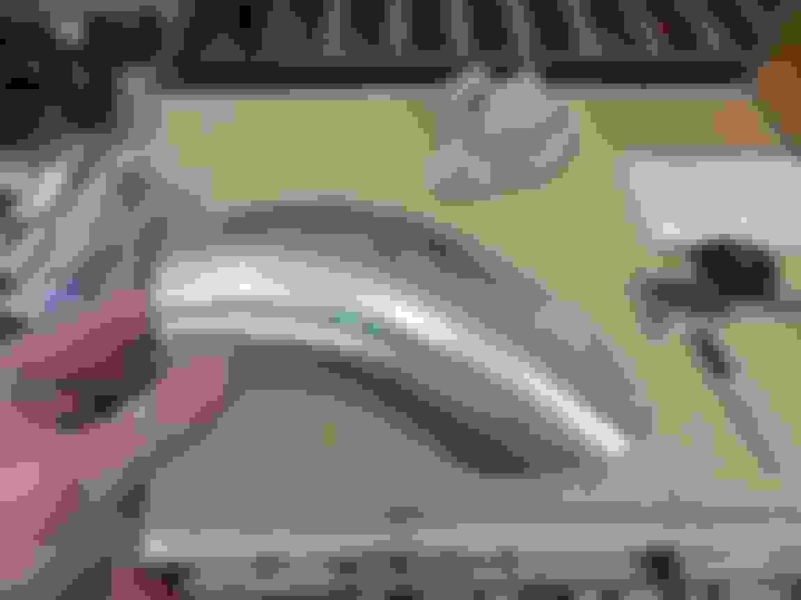
Started on a couple different intercooler things today, including trying to ovalize tubing to give the outlet charge pipe more clearance over the radiator. So I made some tooling!
Worked pretty well! This forms a 3.5" OD tube to 2.5"x4.1" oval.
I anticipated that this first attempt with no taper to the tooling might end up kinking the tubing somewhat, but wanted to try anyways. It's noticeable, but not too bad.. however I still massage the form and added some taper to it to prevent any kinks the next time around..
Next up was to start putting some shape into the 3.5" round pipe sections of the charge pipe. Included some pics of how I cut the U bend, can never have too secure of a fixture setup!
After staring at it for a while, I actually started liking my super basic first "mockup" oval elbow for the intercooler outlet that I made out of a split 2.5" slash cut bend and some cardboard filler. Decided to run with it and make it fully out of aluminum, to have as an option for the intercooler outlet..
Now to just make a 3.5" round -> 2.5"x4" oval transition to link the two parts. The gap where the transition goes is directly over the radiator. I'll wait until I've finalized the radiator and intercooler locations before finishing this piece off with that transition. I'll probably end up pinching the tip of the S bend a bit just to make the transition less abrupt.
And just as an extra point of interest.. after doing all the above, I was curious to see how well the 3.5" mandrel bend would deal with some ovalizing forming, with the residual stresses in the tube from the bending process. Turns out, it doesn't like to be formed again.
Did some manual smoothing/tapering of the wooden form to help the situation with less kinking...
Initial setup before any compression...
This is with about a 1/2" of compression, you can already see the outside wall of the bend wants to collapse seeing as it's already experienced a lot of tension/stretching from the mandrel bending process...
And this it after full compression AKA wood form bottoming out on itself, there's a good 1/4" of spring back and you can see how the corners of the form didn't want to get "filled out" by the tube, and there's more kinking and deformation on the outer side of the bend...
I think your problem is the curvature of the mandrel bend is stiffening things up out of plane. Consider putting a little heat into the material before you form it - that should soften it up plenty for forming. While it's compressed in the die, go around the inside with a hammer and a dolly to "coin" it into the form. It will take the shape better and springback less. If you need to compensate more for springback after that, you can cut the dies where they meet so they can over travel.

 02-20-2018, 02:01 PM