When you click on links to various merchants on this site and make a purchase, this can result in this site earning a commission. Affiliate programs and affiliations include, but are not limited to, the eBay Partner Network.
Was passing my wife today in the Camaro, running about7-8 psi and I heard a loud bang, almost like a shotgun in my ear . Looked out the rear view and saw something Black tumbling across the road. I turn around and go back and it's a chunk of a reinforced 90* coupler that goes behind the bov. I've never seen this before in my life , I've seen pipes blow off but never a coupler explode. What could've caused this to take place ?
Reinforced coupler from Huron . I even eased into it . Cars been seeing 12 psi regularly with zero issues , I've never seen one explode like this though . Always come off the coupler never blow it in half
I think I can explain why it failed. I think it is because you used a 90 there? Normally a Huron kit has a 45 there. The top of the pipe runs from throttle body, and it passes through the hole under the fuse boxes correct? That means it should slope forward towards the front of the car.
I've measured the angle on this pipe with an angle finder on the kit. It doesn't go together well because the angle measures 66 degrees. See the photo with the supplied 45 on it below.
Because it is 66 degrees the supplied 45 is in 21 degrees of compression, at the top on the inside of the elbow. Not the best deal, but it works.
If you put a 90 on there, the inside of the bend would be being stretched by 24 degrees. I think stretching it on the inner part is far more likely to cause it to fail than compressing it. Probably the best solution would be to hunt down a 60 degree silicone elbow. They are uncommon and not even available in most brands, but they do exist out there. The ultimate solution would get a piece of 3" stainless tubing like you have bent to 66 degrees then use 2 strait pieces to join it together. You would need to trim back both existing pieces about 3 " to make room for it to fit, and have to roll new beads on all of the pipe ends.
I'm going to run my 45 until it needs replacing, then I'll buy a 60. Maybe if you still have your 45 from the kit you can fit it in like the picture I have, and not have to spend a cent to fix it.
Yes that's exactly it, I didn't like the way it pinched the 45 at all, the 90* fit so clean and worked for a couple thousand miles flawlessly. I may try the 45 then ,
I actually thought about it and ordered myself a 60 to try to get rid of that bulge. Found one online for $16.
Awesome, thanks for the info. Mine fits like a total piece of **** as well. One would think that this kind of thing would be figured out while putting together such a pricey kit.
Can you guys rotate the pipes to Make it line up any better? That's not acceptable imho I'd be fixing that.
No way to change the angle, it's defined by the location of the throttle body, and the hole the pipe goes through under the fuse box. I think it is fully functional, just kind of ugly looking when viewed from that angle. I took the photo from the angle that makes it look the worst, or shows the problem best.
I would think it to be quite reliable because I haven't heard about it before. There are a large number of these kits out there on F-bodies, if they were coming apart we would know about it. Anyone with a 4th gen F-body turbo car, and a FMIC is going to be having this same issue if they are using the hole under the fuse box for routing, which almost everyone is.
The cosmetics are not really an issue, you can never see it once the bumper cover is on the car. My biggest issue would be that there is a little cross sectional area lost there, so it may be a little flow restriction, like having a slightly smaller throttle body. I would estimate it to be something like a 2.75" diameter cross section through that area rather than the 3" the rest of the system is.
Surely that cant be the way anyone would expect it to fit ? and more importantly why anyone would ever actually fit it and expect it to be reliable ?
That's exactly what it thought, it looked "restrictive, kinked, and the 90* fit much better " I'll throw the other one on today and take it for a ride. I've only got 3-4 days left before snow pummels us again, just wanna enjoy the car
If you play with the lower fuse box plastic as noted in the guide, the pipe to the TB will sit in the correct position and the 45* coupler is the proper one to fit/use.
Before I start please understand this is in no way a knock on the Huron Speed kit, just trying to help us all understand what is going on here, and why a 90 coupler failed, and is wrong for the application. Of anything I've bought in life, I don't think there is anything in the world I could be happier with than the Huron Speed kit. Only regret I have is I didn't wait another 6 weeks and buy a V3 kit. It has some clear improvements. I recommend Huron Speed to anyone that asks 100%, great products, and great service, 5 starts all the way.
To Jon :
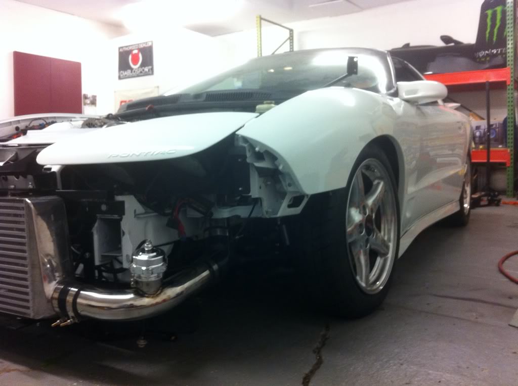
Your's is buckled a little too on the white car, somewhat like mine, just not so much. If I take a picture of mine from the front it looks similar. The photo I took, as I said makes it look the worst it could. The large charge pipe off the TB is forward as far as possible in the hole under the fuse box. The fuse box has been trimmed and does not touch the pipe.
The geometry of the car is such that the plane that runs through the front of the throttle body, and the front edge of the hole under the fuse box is 66 degrees from the horizontal. I've done a considerable amount of chassis fabrication, back halfing etc, and have become good friends with my digital angle finder. This has nothing to do with the kit, just how the car is. That 66 degree angle is fixed, unless you enlarge the metal hole under the fuse box. I actually lined it up with a streight edge, and put an angle finder on it. To make a 45 work perfectly the pipe off the FMIC will need to angle upwards 21 degrees from the horizontal. Simple geometery. You do have it angled up slightly, I'd estimate about 10 degrees based upon your photo. My pipe off the FMIC is basically horizontal. So I have 21 degrees of compression on my 45 silicone elbow. If yours is sloped up at 10 degrees, you still have 11 degrees of compression, which I agree a silicone coupler is easily flexible enough to handle that. Its still not a perfect 45.
If the pipe off the TB were about 2 inches shorter, on the down leg, I could angle the pipe off the FMIC up that much, 21 degrees, and match the 45 bend perfectly. This could also be accomplished by pushing the one end of the throttle body pipe up higher in the engine bay, on the end near the drivers side. Basically clock the pipe in the photo below a few degrees counter clockwise.
Since mine looks good in the engine bay, I don't really want to do that. I like the slight slope to it. You can clearly see the pipe sloping down towards the drivers side of the car. I expect the kit was designed so the coupler off the throttle body points directly at 3 O'clock?
If the section of the pipe off the throttle body went level towards the drivers side of the vehicle, it would raise the bottom of that pipe at the 45 degree coupler an inch or 2 and it would match up just like yours, with only about 11 degrees of compression. You could put angle finders on the pipes in your car next time you have the bumper cover off to determine your exact angle on incidence at your coupler. I bet its more like 55 degrees rather than the 45.
After over thinking this problem way beyond measure, there are 3 solutions for me, clock the throttle body pipe more counter clock wise, to get to about a 55 degree angle at the coupler, and use the 45 with about a 10 degree compression. Or leave it the way it is and buy a 60 for $16, and have about a 6 degree compression. The third solution, the one I'll likely go with, is clock it just a little counter clock wise so I can get the pipe coming off the FMIC angle of 6 degrees up, and have a perfect mating at the coupler.
I think we now have a clear understand of why the OP's 90 failed though. 24 degrees of stretch will kill a coupling in a few weeks, lesson learned.
Last edited by ScottyBG; Nov 28, 2016 at 10:21 AM.
Reason: Spelling
I can see above your charge tubing is off from how we designed it. It should not be angled down when going to the drivers side of the car. I think you need to get it further into the TB coupler and bring the area with the bend up higher. The 45* coupler on the white car is not buckled and the tube in the engine bay runs parallel with the upper radiator support. Hope this helps!
Thanks for the tip. I thought it was bottomed out on the coupler by the throttle body? But I'll need to check it. It will be a couple days before I can get to it. I'll post results with what I find. It doesn't look bad from a quartering view like on the white car.
From your photos it looked like a little dip where the black wire tie was around the middle? My bad if I misinterpreted the photo. Thanks again for all your help, and answering my questions on the install.
Gas Monkey Built a 6-Wheel Ferrari Testarossa With a Corvette LT4 Engine
Slideshow: The controversial Ferrari F6 swaps its original flat-12 for a Corvette Z06-derived LT4 V8 and sends power to four rear wheels through a custom-built drivetrain.
7 Most Reliable High-Performance Engines GM Has Ever Built
Slideshow:These GM engines didn't just make huge power, they survived abuse, boost, track days, and six-digit mileage with a reputation for refusing to quit.
6 Common C5 Corvette Failures and What's Involved In Repairing Them
Slideshow: From wobbling harmonic balancers to failed EBCMs, these are the issues that define long-term C5 ownership and what repairs typically involve.
Retro Modern Bandit Pontiac Trans AM Comes With Burt Reynolds' Autograph
Slideshow: A modern Camaro transformed into a retro icon, this limited-run "Bandit" build blends nostalgia with brute force in a way few revivals manage.
Top 10 Greatest Cadillac V Series Performance Models Ever, Ranked
Slideshow: Cadillac didn't just crash the high-performance luxury vehicle party, it showed up loud, supercharged, and occasionally a little unhinged...