When you click on links to various merchants on this site and make a purchase, this can result in this site earning a commission. Affiliate programs and affiliations include, but are not limited to, the eBay Partner Network.
Maybe, but there's no point in the extra complexity if it's not needed. In this case, there is a real reason to ditch the pusher fan - it's no longer available, was used only on two years of a low production vehicle, and when it fails there is no replacement for it. Designing it out has real value!
But if the fan is already there, and working....there is zero complexity as you do not need to touch it. And the A/C fan is there so you do not have a huge fan running cooling the main engine rad when it is not needed.
the A/C fan will be located close to the A/C core....hence be more efficient at that task. If A/C is needed of course.
The easiest option is to leave it alone. The complex option is to tamper with it.
I'm 100% down for complexity now, while everything is apart and the vehicle isn't in service than complexity later when it's put back together and needs to be dependable. If I can avoid a scenario where three years from now the aux fan fails and I have redo work I could have done now, I will take that approach every time.
BMW PWM fan and Bosch NTC M12 Temp sensor connected to an ECM.
I'm recapping here to keep all the info for this setup in one place.
This is for controlling a BMW PWM controlled fan where the bosch sensor is shared with the ECM.
BTW, this is very similar to the C6 corvette fan controller, so some of this can be reused for that setup
Based on your readings, the series resistance is 1255 ohms.
62F = 3.47v
111F = 2.24v
140F = 1.61v = 596 ohms = ((5 - 1.61) / 1.61) * 596 = 1255 ohm series resistance
185F = .93v
200F = .77v
210F = .68v
I'm trying to keep the arduino code simple, so I decided to do the math calculations in an excel spreadsheet instead of in the code.
I plugged in the series resistance of 1255 into column E
So based on the spreadsheet, at 176F degrees, the pwm will be 242 (95%). At 212F, the PWM will be 13 (5%) and anything in between will proportionally change the pwm from 5% to 95%.
This is amazing stuff! I have some components to buy I think.... I probably have the resistors but probably not the transistors.
Would you be willing to link to the spreadsheet and text file of the code (so I don't have to retype it ) ? I could throw up a writeable onedrive folder maybe?
I bought this Jeep in 2016, drove it 370 miles (100 of which was the trip home), and it's been parked ever since due to a massive rear main seal leak. It's just been sitting... It's done another 120 miles in the last week which feels really positive. There is a light film of oil collecting on the bottom of the bell housing after a 20 mile drive, but I think it may be leftovers... I scrubbed the entire motor to spotless during reassembly, but I forgot to clean the puddle out of the bell housing (DOH!) and that's what I'm seeing now. The issue is nothing like before so I'm pretty confident this thing is mechanically dialed.
I finished the electrical wiring for the fan over the weekend (located the relay, installed a maxi fuse, etc.) so this magic box is the final piece. Speaking of, I need to find a box for it too!
You don't need the spreadsheet for now. But if you wanted it, you could just type in the formulas and the table from the bosch sensor. The rest excel generates.
Here is copyable code. It's mostly comments so if you wanted to type it in yourself, it's not too bad.
// This a test program, no warranties are implied or given. PWM BMW shared Bosch sensor V1
// Use, copy any modify this test program any way you want, at your own risk. Then test, test, test
// It reads a Bosch temp sensor shared with an ECM and controls a BMW PWM controlled fan.
// BMW fan: 5% duty = full, 95% = off, no PWM = full Freq = 100Hz, PWM signal is 12 volt
// Bosch temp sensor is NTC M12 with a 1255 ohm series resistor in the ECM to 5 volts
#include <PWM.h>
/*----------------------- User adjustable variables and preferences section ---------------------------------*/
// FYI: readingForFanStartup and readingForFanOnFull are based on a spreadsheet for bosch sensor and series resistance
const int readingForFanStartup = 209; // analog reading low temp. Below this temperature, the fan will be off
const int readingForFanOnFull = 133; // analog reading high temp. Above this temperature, the fan will be on at full power
// FYI a PWM duty ranges from 0 to 255. Set desired temperature range below
const int fanOnFullDuty = 13; // duty for 5% (full speed = 5% of 255)
const int fanDutyOff = 242; // duty for 95% (off fan speed = 95% of 255)
const int fanPwmOutPin = 9; // PWM output pin to transistor 0 or 5 volts.
const int tempSensorPin = A0; // Pin to read analog voltage from the temp sensor.
void setup() { /* ++++++++++++++++++ Setup is run once when the arduino boots ++++++++++++++++++++++++++*/
InitTimersSafe(); // set timers for custom PWM frequency
SetPinFrequency(fanPwmOutPin, 100); // set pwm frequency to 100 Hz for BMW pwm
pwmWrite(fanPwmOutPin, 255 - fanDutyOff); // start with fan off
} // end setup
void loop() { /* ++++++++++++++++++ Main Loop, continuously loops forever ++++++++++++++++++++++++++++*/
delay(1000); // only get and adjust temperature once per second
int analogTempReading = analogRead(tempSensorPin); // read temperature sensor (range 0 to 1023)
int pwmDuty = map(analogTempReading, readingForFanStartup, readingForFanOnFull, fanDutyOff, fanOnFullDuty ); // calc PWM Duty
pwmDuty = constrain(pwmDuty, fanOnFullDuty, fanDutyOff ); // PWM duty is never allowed ouside of min or max duties
pwmWrite(fanPwmOutPin, 255 - pwmDuty); // send PWM to output pin (invert pwm for 12 volt transistor)
} // end main loop
I haven't moved on this.... work has been a disaster, and as it turns out when it's 40F-50F out you don't even need a cooling fan on this thing. 300 miles on surface streets and not once has engine temp gone above 190F. It's supposed to warm up a bit this weekend, so I'll get to work on wiring this up, and charging the AC. Why charge the AC? Because when the AC pressure transducer shows an out of range value it runs the factory electric ("AC condenser") fan at max speed all the time. I pulled the relays out to solve that issue.
I've been following this, but still need to ask- how can I do this "economically" on my '04 Tahoe w/ LM7/4L60E?
I plan on using the '05-up GM truck twin fan setup, and would prefer NOT to tie into the OEM ECM.
I've looked into the DCC FK45 PWM fan control, and the similar unit from Power Systems Management (Carl Casanova of VaporWorx fame) distributed via Northern Radiator.
Either of the above is north of $150-185. If I can do it just as well for less, would be very welcome.
A component list and wiring diagram will elicit my undying gratitude, if it works well.
What drives these fans from the factory? Is it PWM controlled or relays? Factory wiring diagram would help me.
I believe it is a relay system as the factory does it. I would prefer a PWM driven setup for its efficiency and not shocking the electrical system with high sudden loads. Even the factory system is guilty of this.
I would prefer a standalone PWM system, similar to what I would have with either the DCC or PSM units, but hopefully at a lower cost.
If you're looking for a DIY low cost solution, then post #1 of this thread should do it. It is standalone and doesn't require any ECM. I use that power module in my twin fan setup, but I don't know the current requirements of yours.
If you want to try something with the C6/Ford controller, I can draw that up for you as a standalone.
FYI- The fans I would use have a combined 40-50 continuous amp draw at full speed.
Also, I would need to have fans activated when the A/C comes on. I'm thinking of using a binary switch to let the rising pressure actuate the fans. Or just tap into the compressor clutch wiring.
After perusing the schematic in post #1, is the temperature range decided by which particular temp sensor is used? It was never mentioned in the accompanying text, or at least I don't recall seeing it mentioned.
It's an NTC 10K Ohm 1% 3435 Thermistor Temperature Sensor.
I have not done extensive maximum current carrying tests for either the Mitsubishi or the Corvette C6 units. I have the Mitsu units running dual fans, but I suspect my fans are lower current than yours.
Based on the construction, I would think the C6 units may be a better choice for your application. If you want to try the C6 unit, I'll post up a complete diagram and code with A/C.
I know ZIP about code and programming. Who could do this?
I've got the program mostly written. It's very similar to the one for the BMW PWM fan. Can you get your hands on a C6/Ford PWM module and can you wire a circuit board similar to what I've show? If so, I'll post the code.


 01-23-2021, 05:38 PM


 If I can avoid a scenario where three years from now the aux fan fails and I have redo work I could have done now, I will take that approach every time.
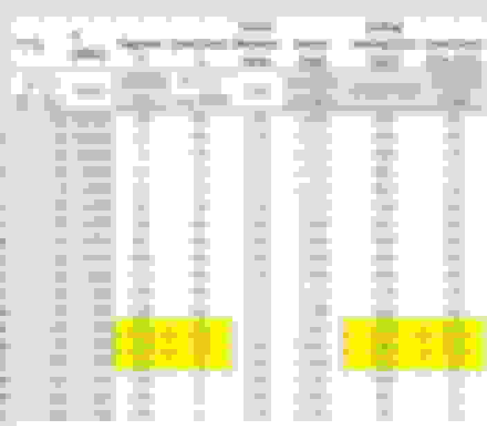


 There is a light film of oil collecting on the bottom of the bell housing after a 20 mile drive, but I think it may be leftovers... I scrubbed the entire motor to spotless during reassembly, but I forgot to clean the puddle out of the bell housing (DOH!) and that's what I'm seeing now. The issue is nothing like before so I'm pretty confident this thing is mechanically dialed.

