


LS Wiring Harness Cleanup - Build

Thread Starter
Teching In
Joined: May 2014
Posts: 39
Likes: 1
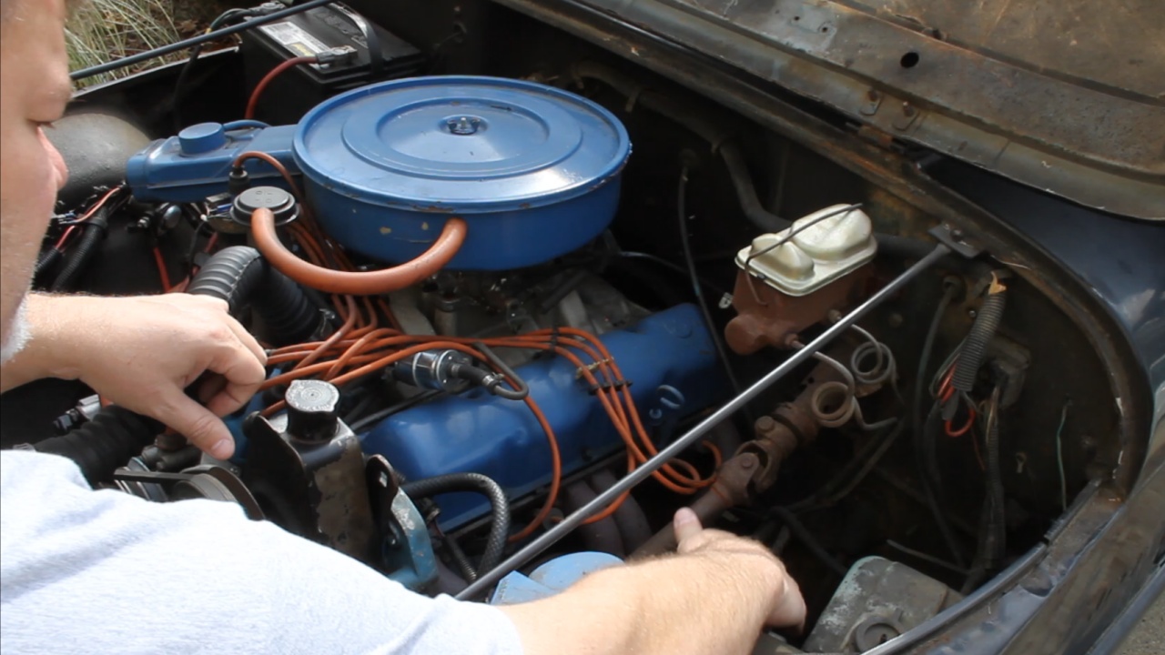
As part of an LM7 swap in my 79 Jeep CJ7 (owned for 28 years). I have just completed a rebuild of an LM7 5.3L GM engine from a 2001 Silverado.
I have documented the engine build here: https://ls1tech.com/forums/generatio...l#post19489634
The next step is to work on the Wiring Harness. The plan is to create a stand a lone harness, remove all of the wires and connectors that will no longer be used, build a Fuse Block with Relays, and build the ODB2 connector.
The plan here is to provide many pictures and videos of our progress.
Thread Starter
Teching In
Joined: May 2014
Posts: 39
Likes: 1
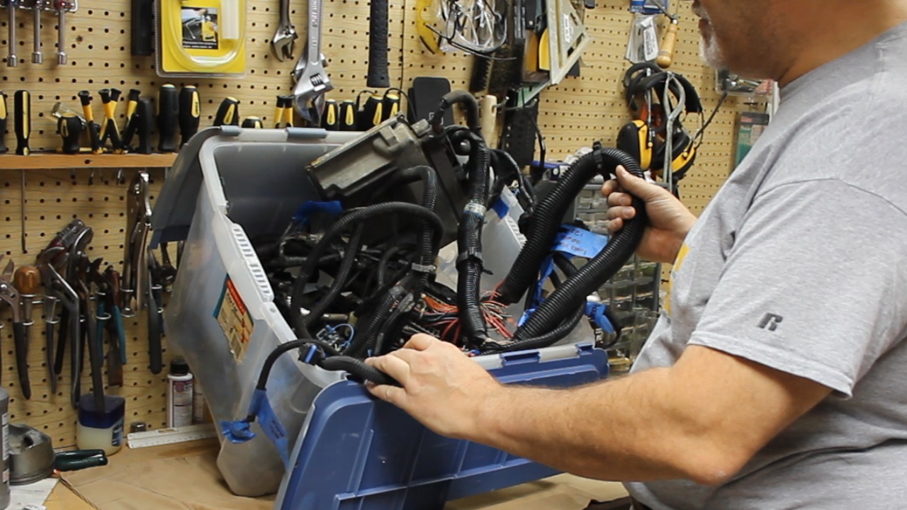
After a bunch of research, we finally got started on the Wiring Harness Cleanup. The plans are to remove all wires that are not needed, build a 4 Fuse Block with 2 Relays, and an ODB2 Connection.
Here is how we left the harness after it was removed from our engine. This is from a 2001 Chevy Silverado, 5.3L LM7.
The steps that we are about to take will be extremely transferable to any Gen3 or Gen4 GM engine. The process will all be roughly the same, but there will be different decisions that would need to be made.
One of the most important decisions that needs to be made up front is where you intend to locate the PCM. This determines one of two approaches on how the wiring process will be performed.

For my application, I plan to locate the PCM on the backside of the Driver's side inner wheel well.
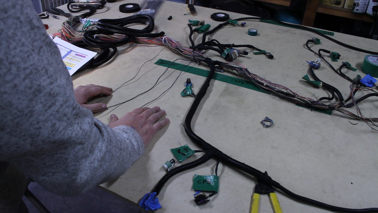
We took some time stretching out the harness and anchored it to a piece of plywood. This will help us organize our process.
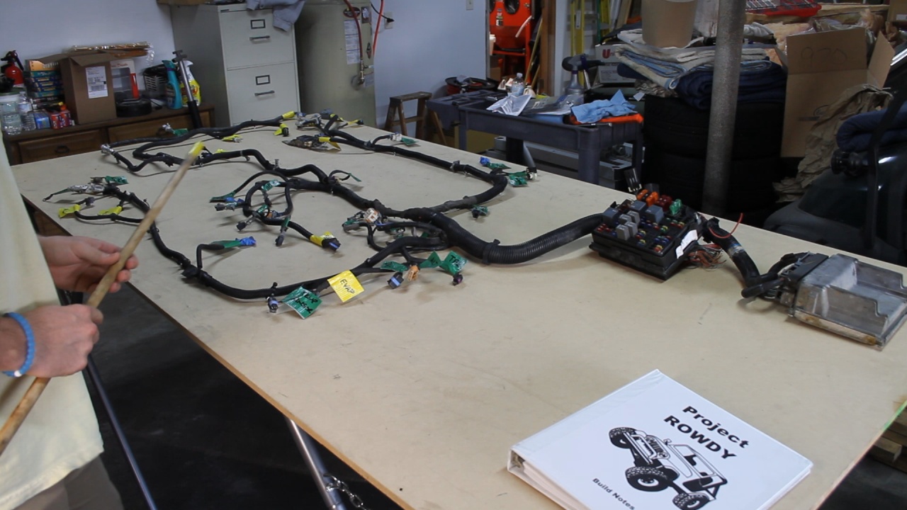
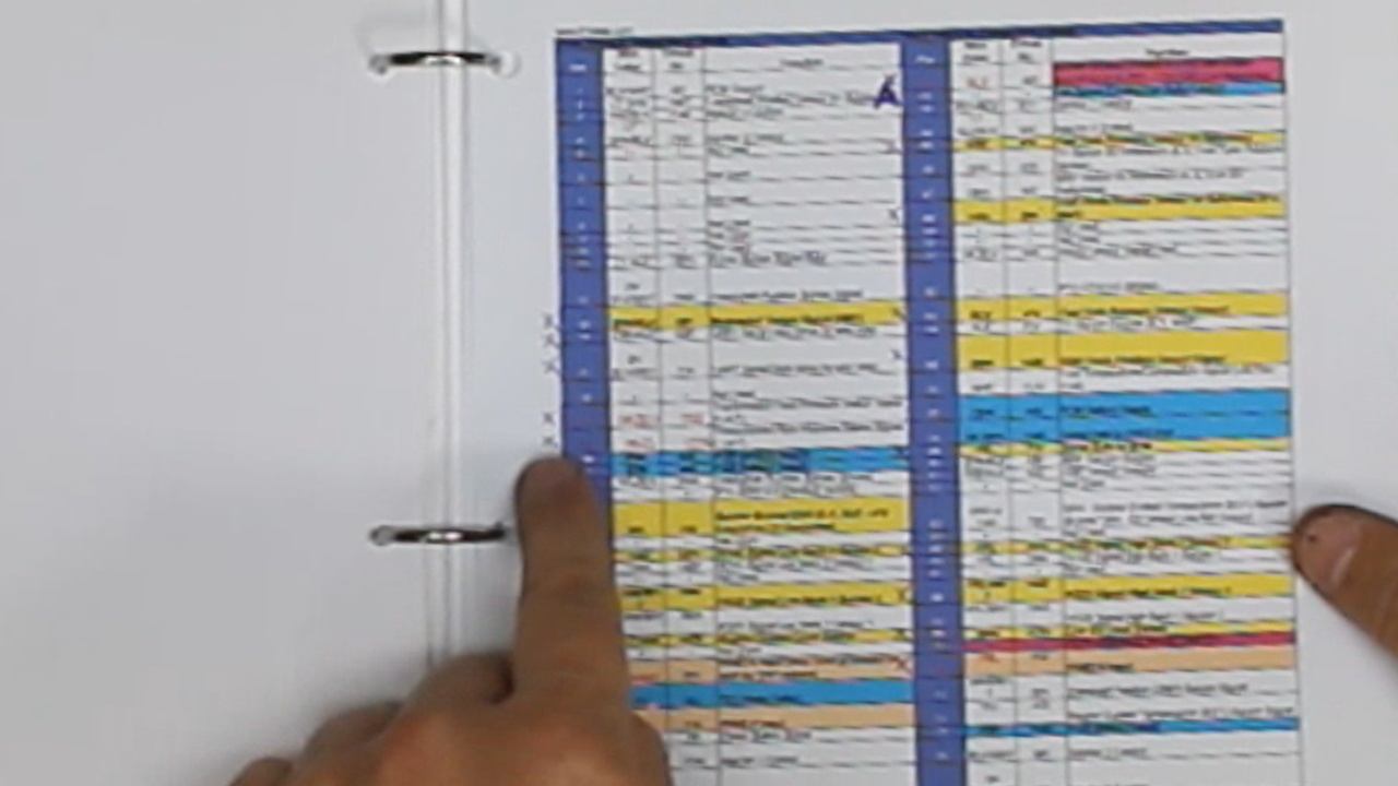
Next, we labeled each connector. We used GREEN tape for the connectors and wires that we plan to retain. We used YELLOW tape for the connectors that should be removed.
We downloaded many documents from LT1Swap.com. Brendan has done a fantastic job collecting and presenting documents for all of the configurations. Visiting this site is a must!
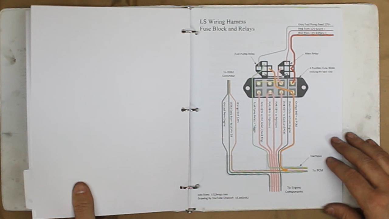
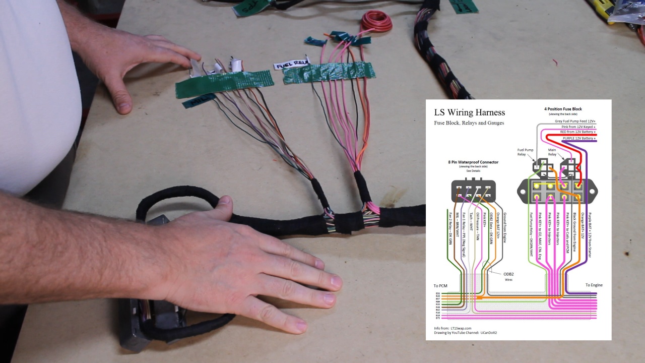
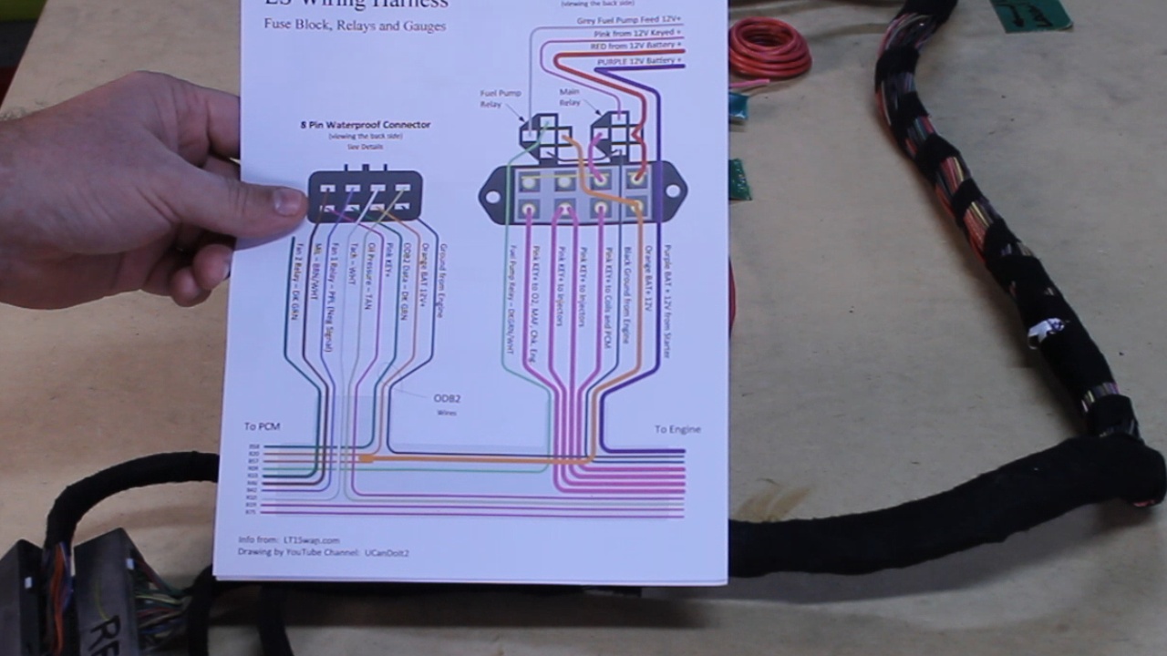
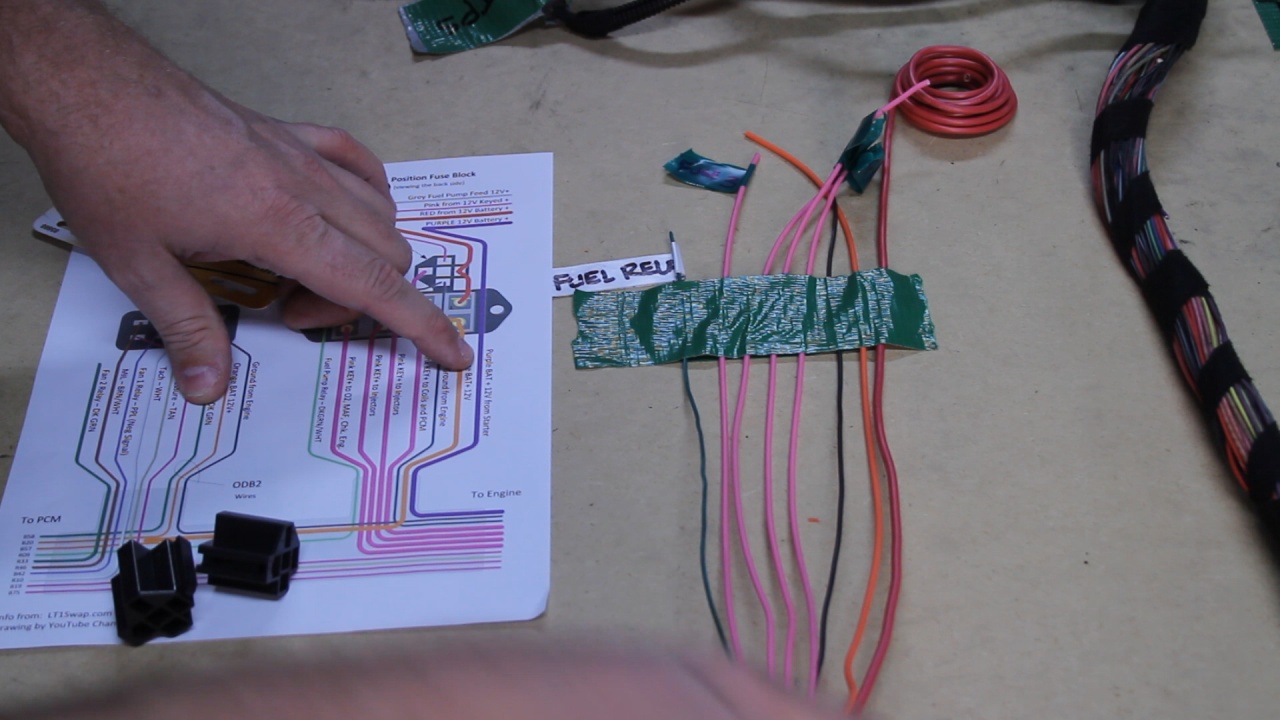
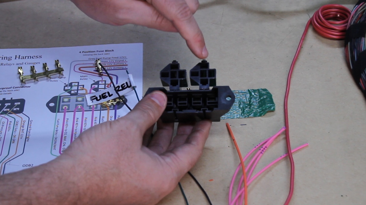
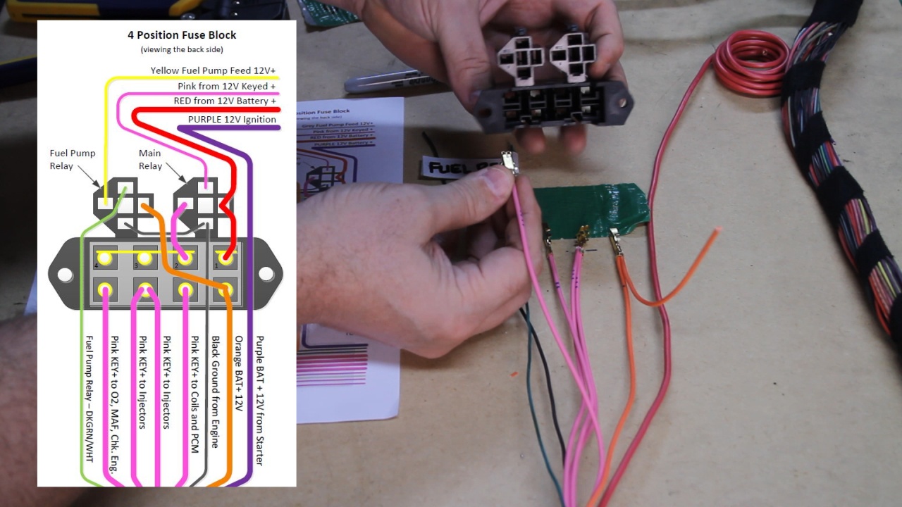
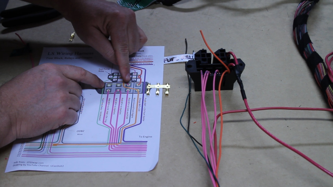
Based on some photos, I was able to create the following diagram which I will use to wire my new Fuse Block. This also includes 2 relays, one as a main harness switch and the other it the Fuel Pump Relay.
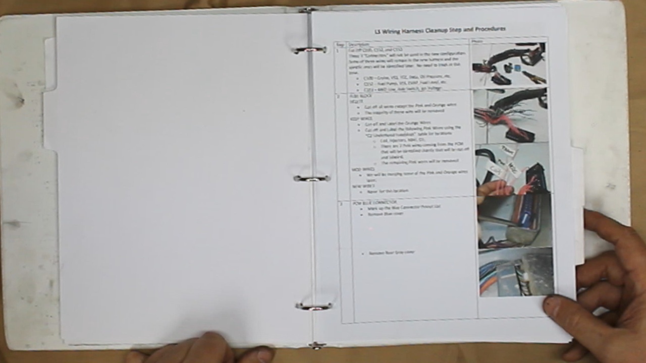
And finally, I put together a list of steps and photos from Brendan's collection that I will use during the Big Snip!
Here is how we left the harness after it was removed from our engine. This is from a 2001 Chevy Silverado, 5.3L LM7.
The steps that we are about to take will be extremely transferable to any Gen3 or Gen4 GM engine. The process will all be roughly the same, but there will be different decisions that would need to be made.
One of the most important decisions that needs to be made up front is where you intend to locate the PCM. This determines one of two approaches on how the wiring process will be performed.
For my application, I plan to locate the PCM on the backside of the Driver's side inner wheel well.
We took some time stretching out the harness and anchored it to a piece of plywood. This will help us organize our process.
Next, we labeled each connector. We used GREEN tape for the connectors and wires that we plan to retain. We used YELLOW tape for the connectors that should be removed.
We downloaded many documents from LT1Swap.com. Brendan has done a fantastic job collecting and presenting documents for all of the configurations. Visiting this site is a must!
Based on some photos, I was able to create the following diagram which I will use to wire my new Fuse Block. This also includes 2 relays, one as a main harness switch and the other it the Fuel Pump Relay.
And finally, I put together a list of steps and photos from Brendan's collection that I will use during the Big Snip!
Last edited by UcanDoIt2; May 8, 2017 at 10:08 PM.
Thread Starter
Teching In
Joined: May 2014
Posts: 39
Likes: 1
Here is a continued look at what we accomplished this week. After a good bit of research and marking up tables and charts, it was finally time to start hacking wires.
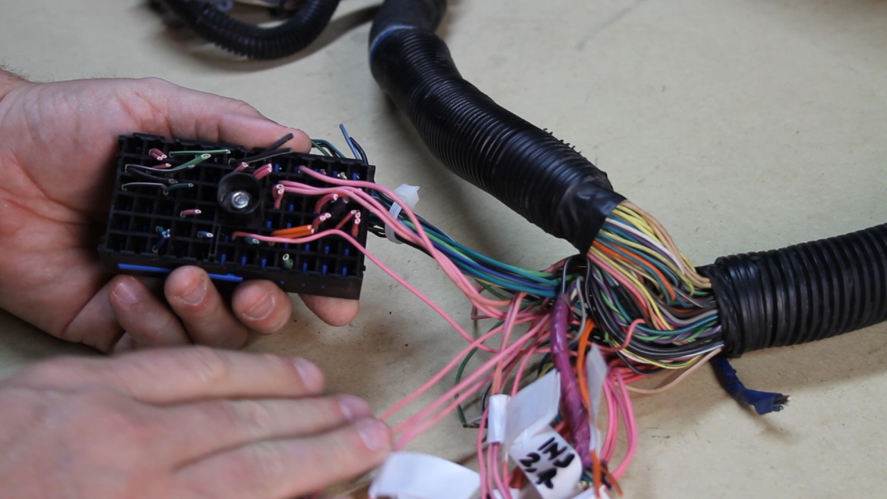
It all started with the 3 remove harness connectors (C100, C152, and C153) I believe these are used to primarily communicate with other parts of the car. From the standpoint of these three connectors, there are only 4 wires that I will be keeping and they are all located in the C100 piece.
Next, I was able to remove all of the non-PINK and non-Orange wires from the original Fuse Block.
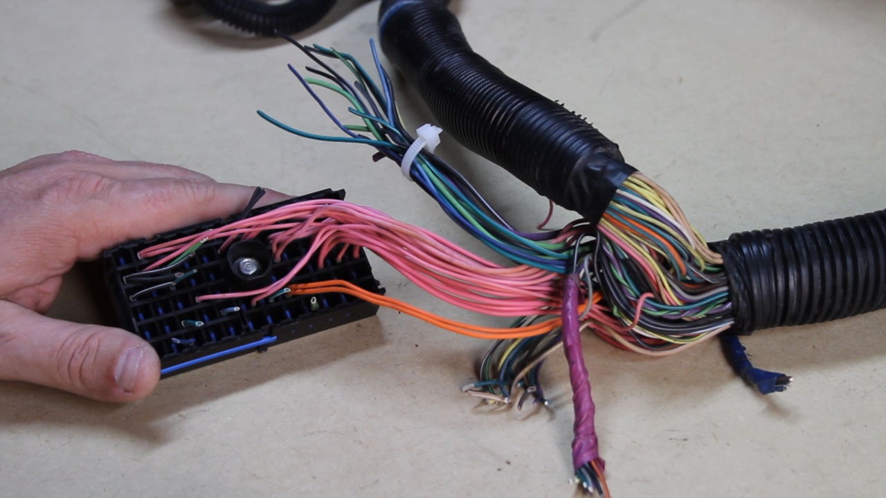
The Orange Wires were cutoff and labeled (BAT+) and select Pink wires were cutoff and labeled with the devices that they provide Switched Power.
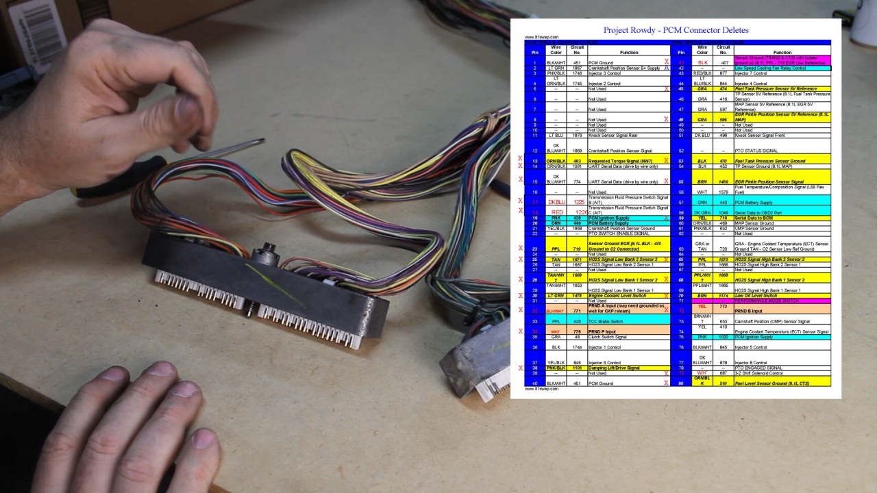
Here is a look at the plan for wires to be removed from the Blue PCM connector
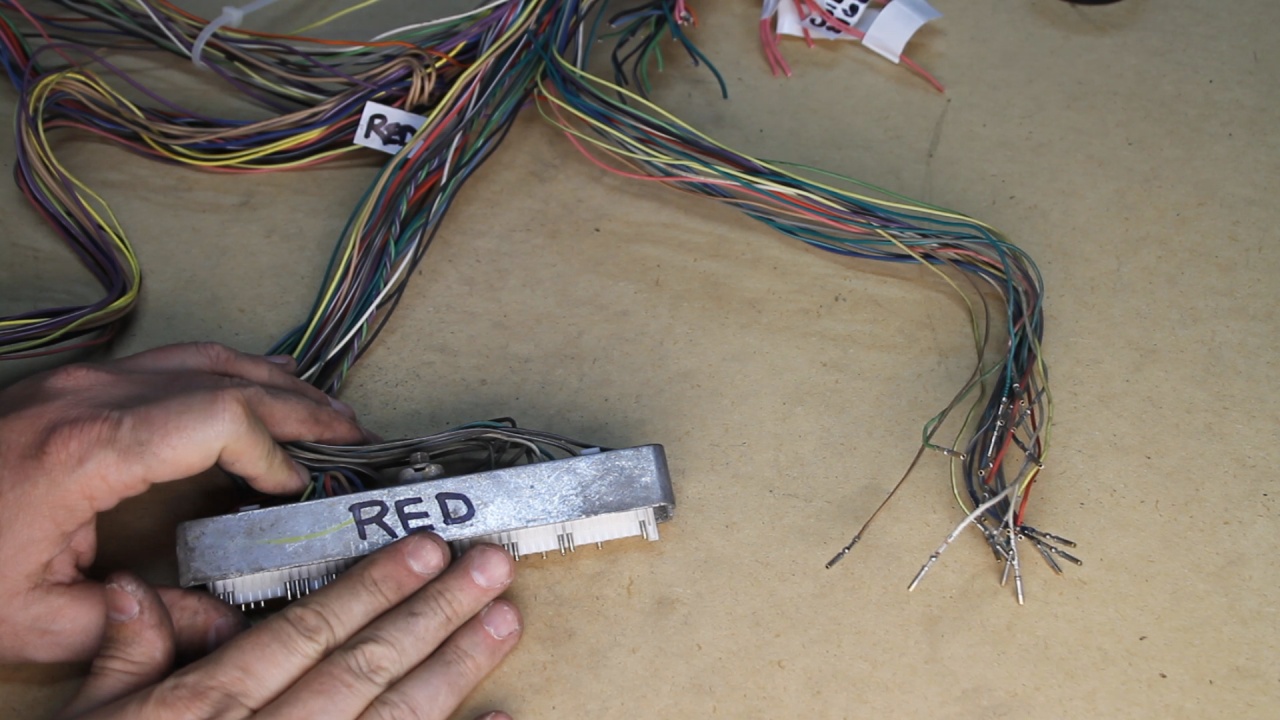
De-pinning is not difficult at all.
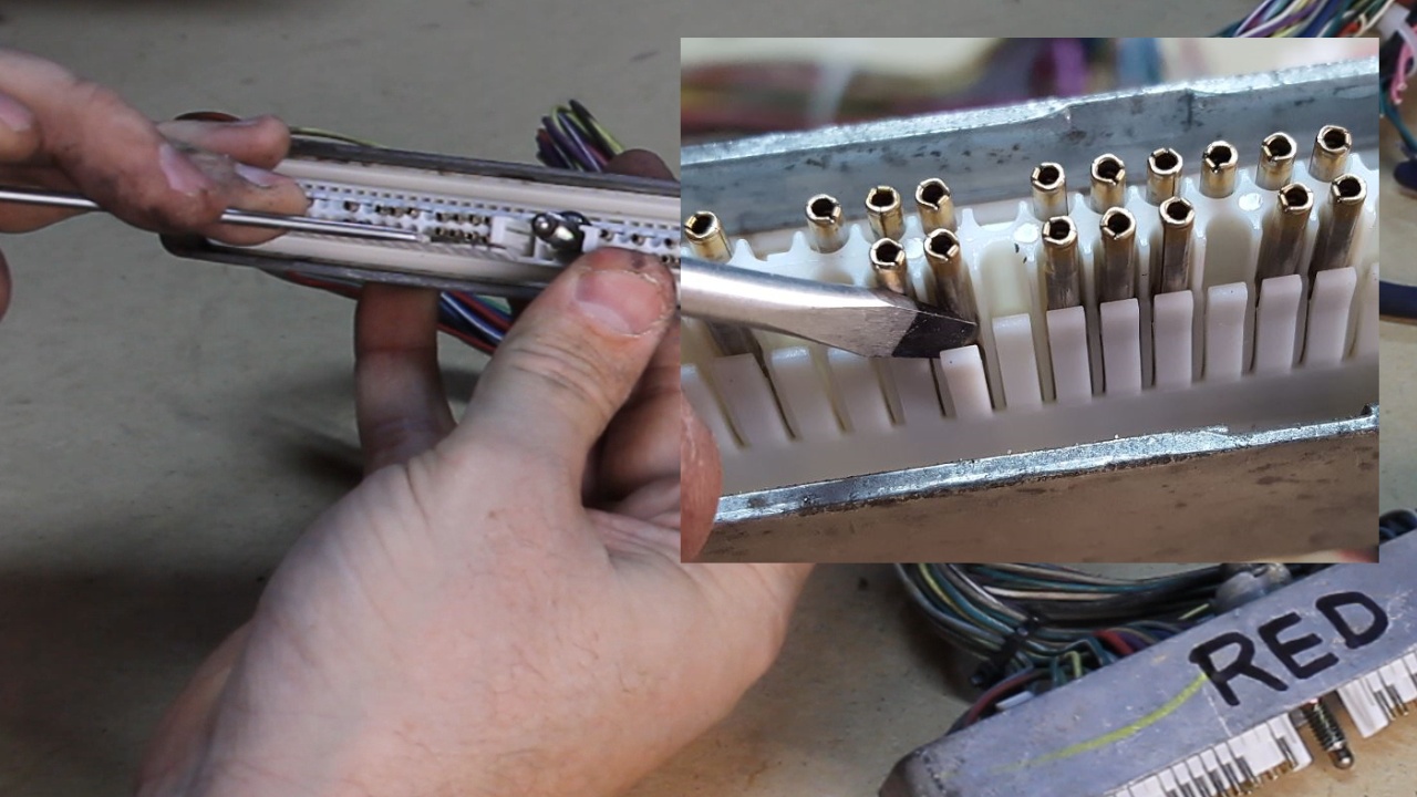
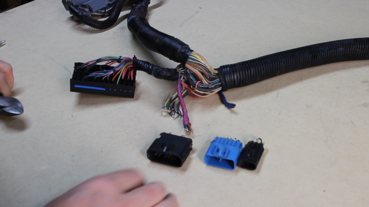
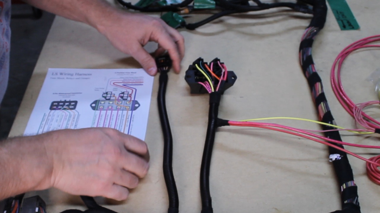
Here are the Blue and Red PCM connectors after I de-pinned the unwanted wires.
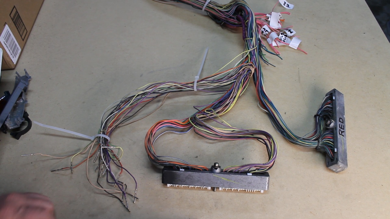
Here is a look after I pulled the unwanted wires out of the front part of the harness all the way back to the first split.
Next, I will be working down each of the smaller legs of the harness with the goal to remove all of the connectors that I have labeled in Yellow (to be removed). More about that, next time...
It all started with the 3 remove harness connectors (C100, C152, and C153) I believe these are used to primarily communicate with other parts of the car. From the standpoint of these three connectors, there are only 4 wires that I will be keeping and they are all located in the C100 piece.
Next, I was able to remove all of the non-PINK and non-Orange wires from the original Fuse Block.
The Orange Wires were cutoff and labeled (BAT+) and select Pink wires were cutoff and labeled with the devices that they provide Switched Power.
Here is a look at the plan for wires to be removed from the Blue PCM connector
De-pinning is not difficult at all.
Here are the Blue and Red PCM connectors after I de-pinned the unwanted wires.
Here is a look after I pulled the unwanted wires out of the front part of the harness all the way back to the first split.
Next, I will be working down each of the smaller legs of the harness with the goal to remove all of the connectors that I have labeled in Yellow (to be removed). More about that, next time...
Last edited by UcanDoIt2; May 8, 2017 at 10:11 PM.
Wow, great job. I went wayyyy overbudget on my engine and spent my speartech harness money. Since I have the original harness and a lot of time, I might dive into it and do the same. Thanks for the tremendous amount of information.
Trending Topics
Thread Starter
Teching In
Joined: May 2014
Posts: 39
Likes: 1
It has been a busy week with a lot of family things.
Was able to completely remove all of the unwanted connectors and related wires. This was quite time consuming because that old Loom and Tape doesn't give up its grip easily.
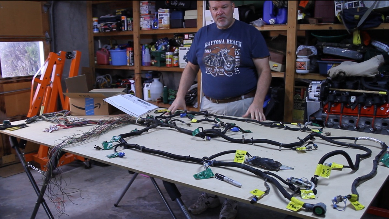
Here is a photo of the harness spread out on the table. We are going to work on the right hand side and remove all of the connectors labeled with Yellow Tape.
It all starts with removing the Loom
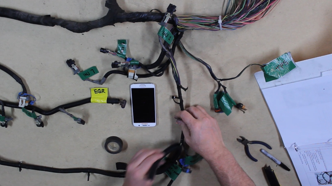
Then the Tape
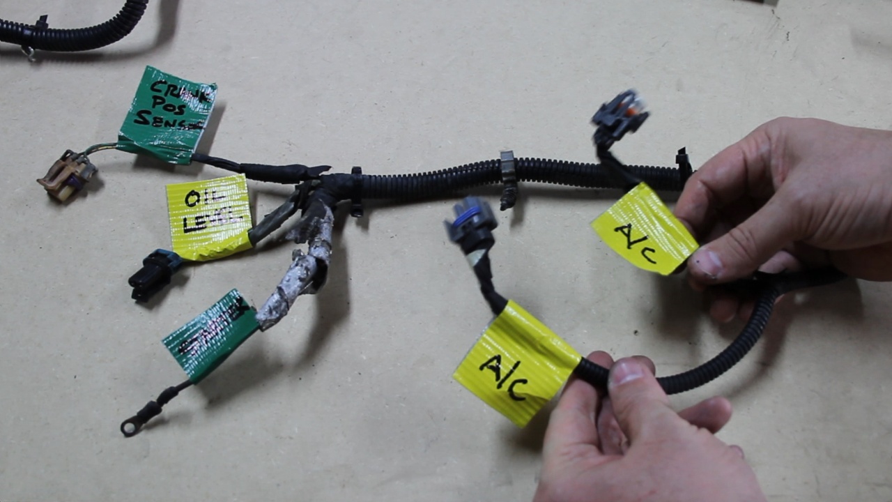
As I ran into tasks that I could not immediately complete, I would wire instructions on Yellow tape to handle later.
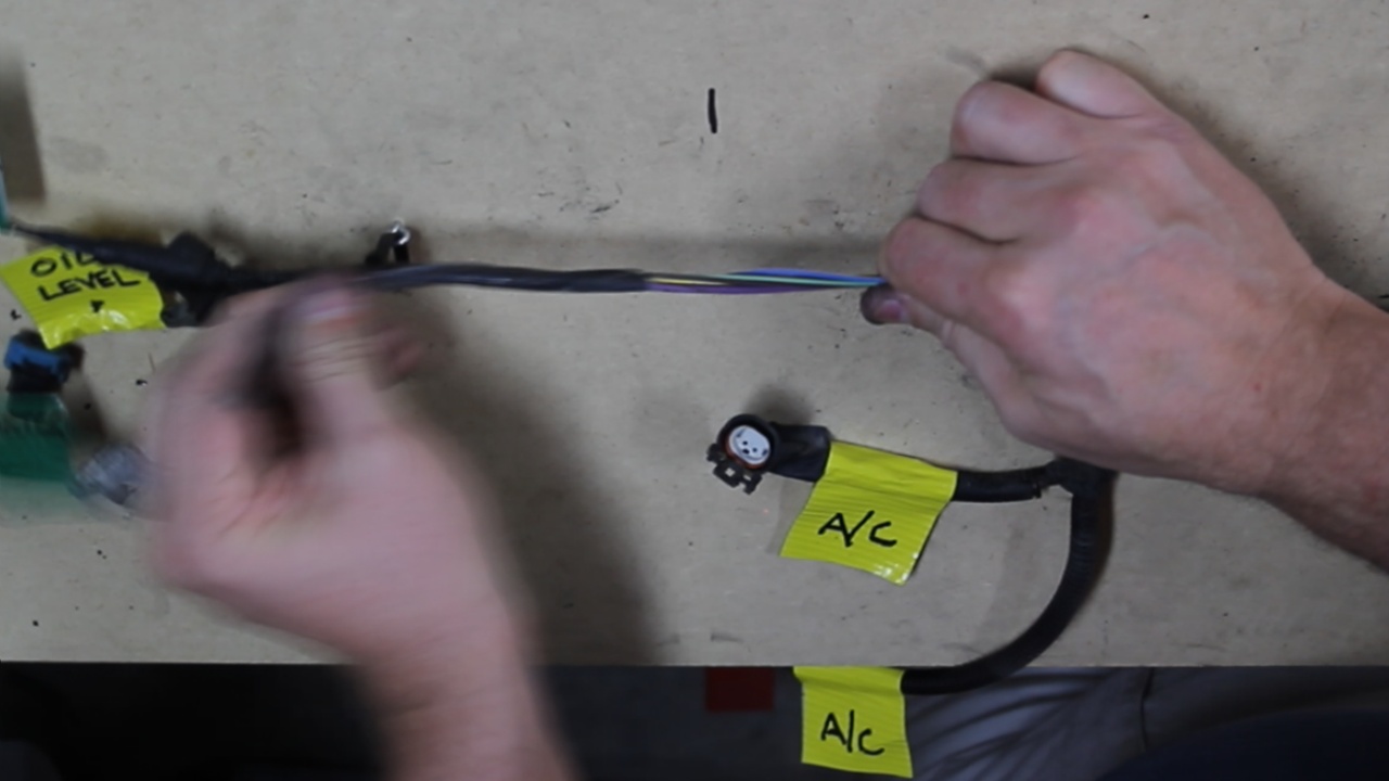
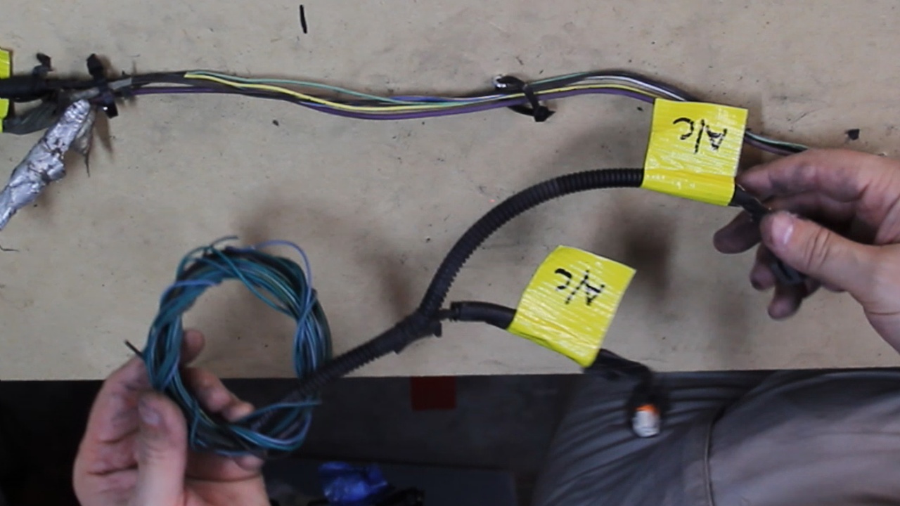
After tracing all the wires of the A/C Compressor, I was able to pull those wires through the harness and remove them completely. The wire that I had issue with was a Black Ground wire which went deeper into the harness that was not yet de-loomed. That is what I marked up in the previous photo to handle later.
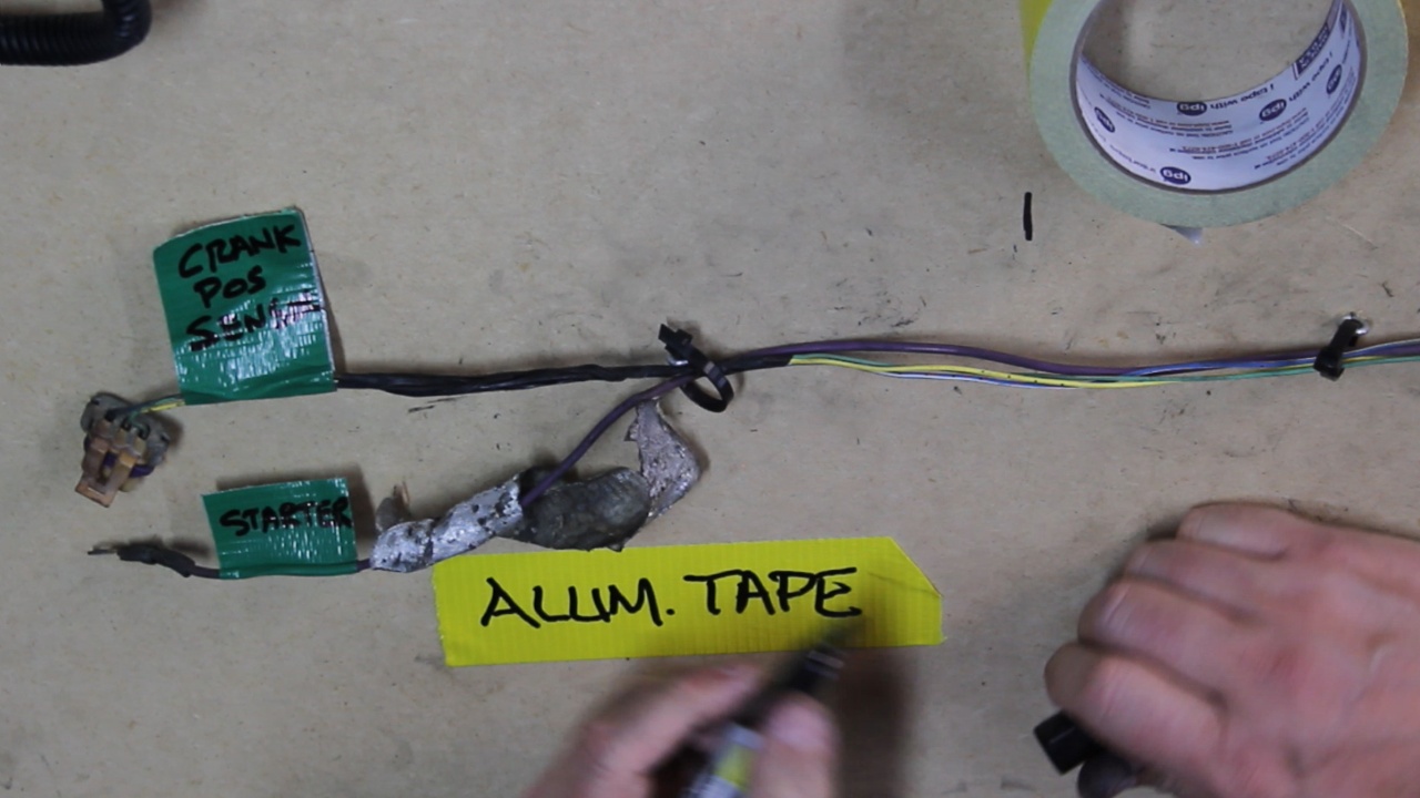
The Starter Battery+ wire had some Aluminum Tape wrapped around it to protect it from heat off the exhaust manifolds. I marked this with a Yellow note to handle later.
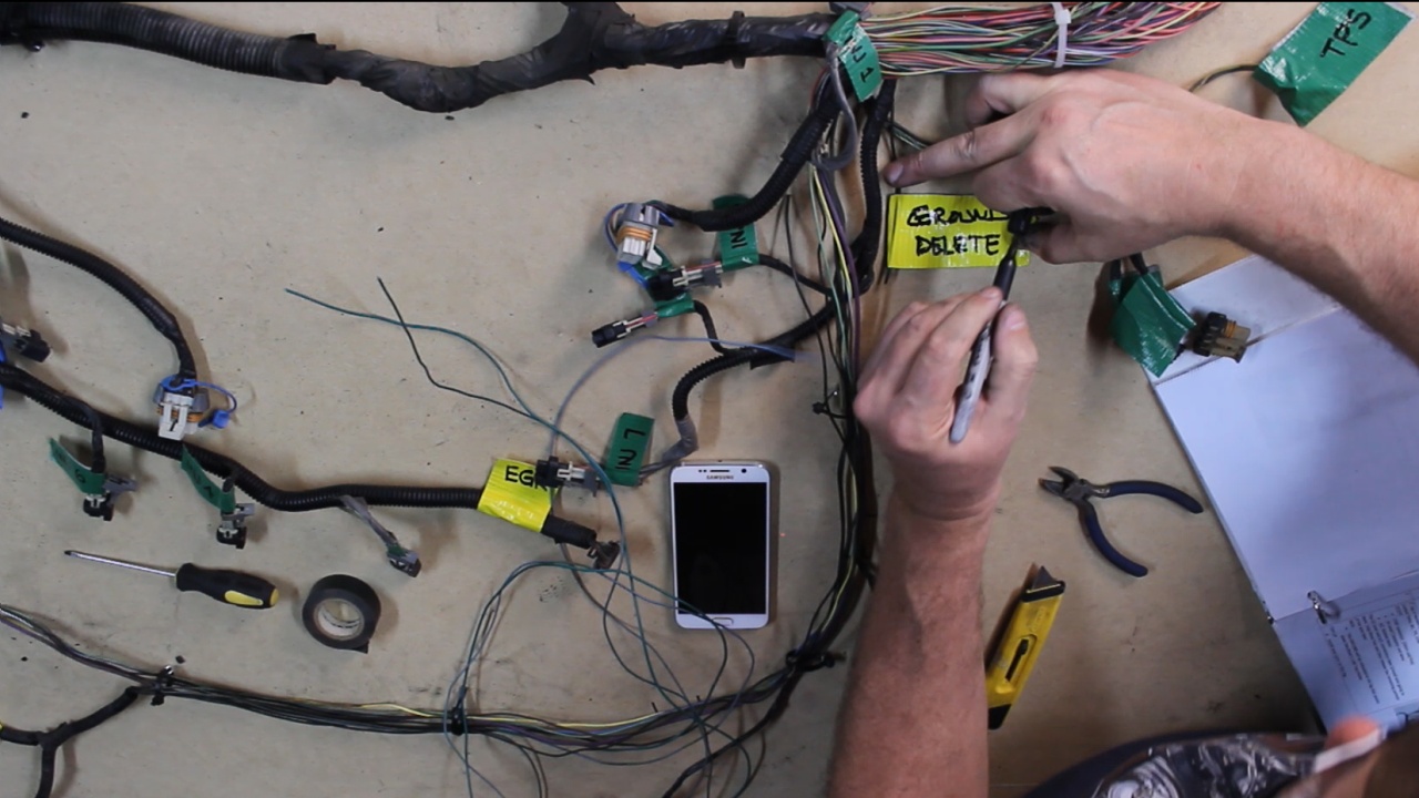
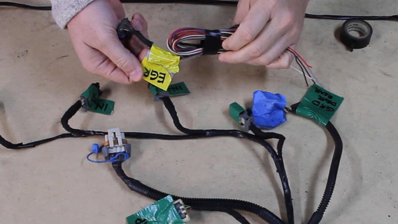
Continued remove all connectors Labeled in Yellow. Here the EGR connector has just been removed.
Since I am not running an Automatic Transmission, I have removed all of the related wires seen here.
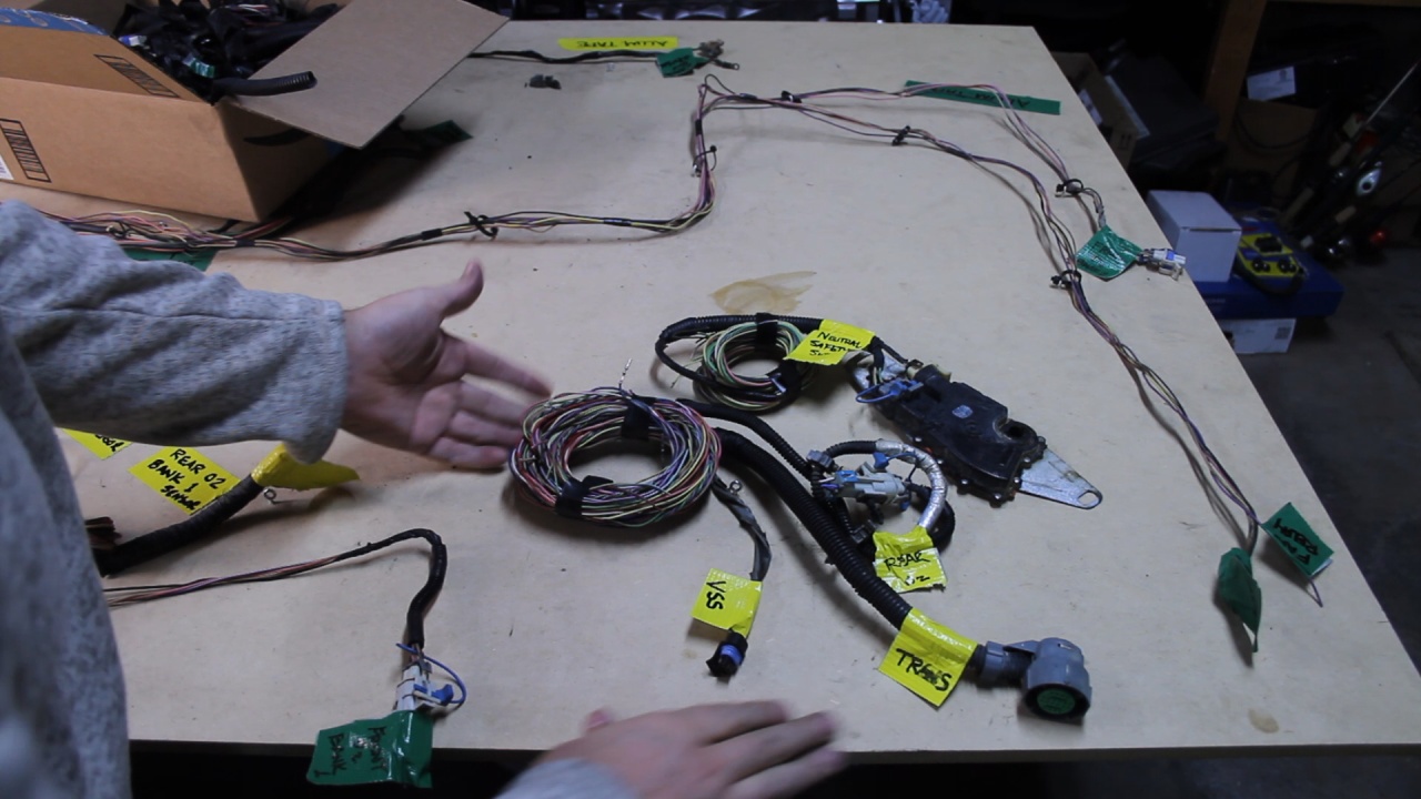
I had to do a little extra research so that I could understand what was taking place with the O2 Sensor wires. After I sorted that all out, the proper wires were cut and removed.

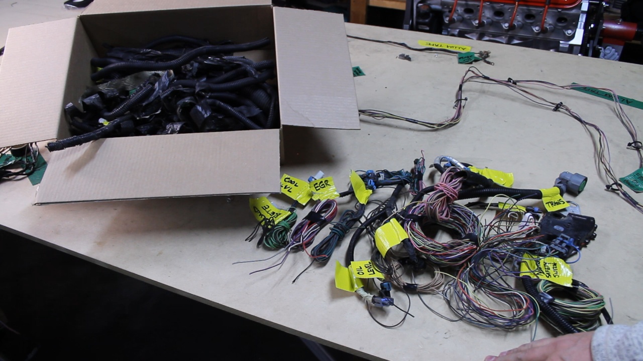
Here is a look at all of the wires and connectors that were removed. You can also see a box that contains all of the Loom and Tape that was removed.
Next, I will be re-Taping and adding new Loom to cover the more slender bundles.
Was able to completely remove all of the unwanted connectors and related wires. This was quite time consuming because that old Loom and Tape doesn't give up its grip easily.
Here is a photo of the harness spread out on the table. We are going to work on the right hand side and remove all of the connectors labeled with Yellow Tape.
It all starts with removing the Loom
Then the Tape
As I ran into tasks that I could not immediately complete, I would wire instructions on Yellow tape to handle later.
After tracing all the wires of the A/C Compressor, I was able to pull those wires through the harness and remove them completely. The wire that I had issue with was a Black Ground wire which went deeper into the harness that was not yet de-loomed. That is what I marked up in the previous photo to handle later.
The Starter Battery+ wire had some Aluminum Tape wrapped around it to protect it from heat off the exhaust manifolds. I marked this with a Yellow note to handle later.
Continued remove all connectors Labeled in Yellow. Here the EGR connector has just been removed.
Since I am not running an Automatic Transmission, I have removed all of the related wires seen here.
I had to do a little extra research so that I could understand what was taking place with the O2 Sensor wires. After I sorted that all out, the proper wires were cut and removed.
Here is a look at all of the wires and connectors that were removed. You can also see a box that contains all of the Loom and Tape that was removed.
Next, I will be re-Taping and adding new Loom to cover the more slender bundles.
Last edited by UcanDoIt2; May 8, 2017 at 10:12 PM.
LS1 Tech Stories
The Best V8 Stories One Small Block at Time

Gas Monkey Built a 6-Wheel Ferrari Testarossa With a Corvette LT4 Engine
Verdad Gallardo
7 Most Reliable High-Performance Engines GM Has Ever Built
Verdad Gallardo
Amazing '71 Camaro Restomod Is Modern Muscle Car Under the Skin
Verdad Gallardo
6 Common C5 Corvette Failures and What's Involved In Repairing Them
Pouria Savadkouei
Retro Modern Bandit Pontiac Trans AM Comes With Burt Reynolds' Autograph
Verdad Gallardo
Top 10 Greatest Cadillac V Series Performance Models Ever, Ranked
Pouria Savadkouei
Top 10 Most Powerful Chevy Trucks Ever Made!

Hennessey's New Supercharged Silverado ZR2 Has 700 HP
Verdad Gallardo
Coachbuilt N2A Anteros Is an LS2-Powered C6 Corvette In Italian Clothes
Verdad Gallardo
Teching In
Joined: May 2012
Posts: 27
Likes: 0
Great job! Something that made this task easier for me was I went to FedEx office and had them print the pin connector diagrams on heavy 11x17 stock. By having the larger pages it was easier on my old eyes and stood up,to the constant handling.
Last edited by 65gregg; Jan 29, 2017 at 08:10 PM.

Teching In
Joined: Feb 2017
Posts: 12
Likes: 0
Hi All
UcanDoit2, how much time will you have in the wiring cleanup? I'm in process of an Lm7 swap for a customer right now. I've never done of one of these and I'd like to make sure I do right by my customer. There are a number of stand alone options out there from $500 and up depending on y our options. I'm thinking at my rate I could pass that easily with labor.
You're doing great looking work and the documentation is commendable.
Thanks for what you are doing.
Thread Starter
Teching In
Joined: May 2014
Posts: 39
Likes: 1
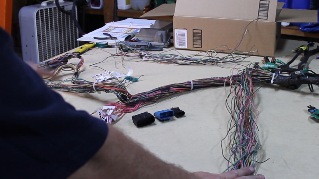
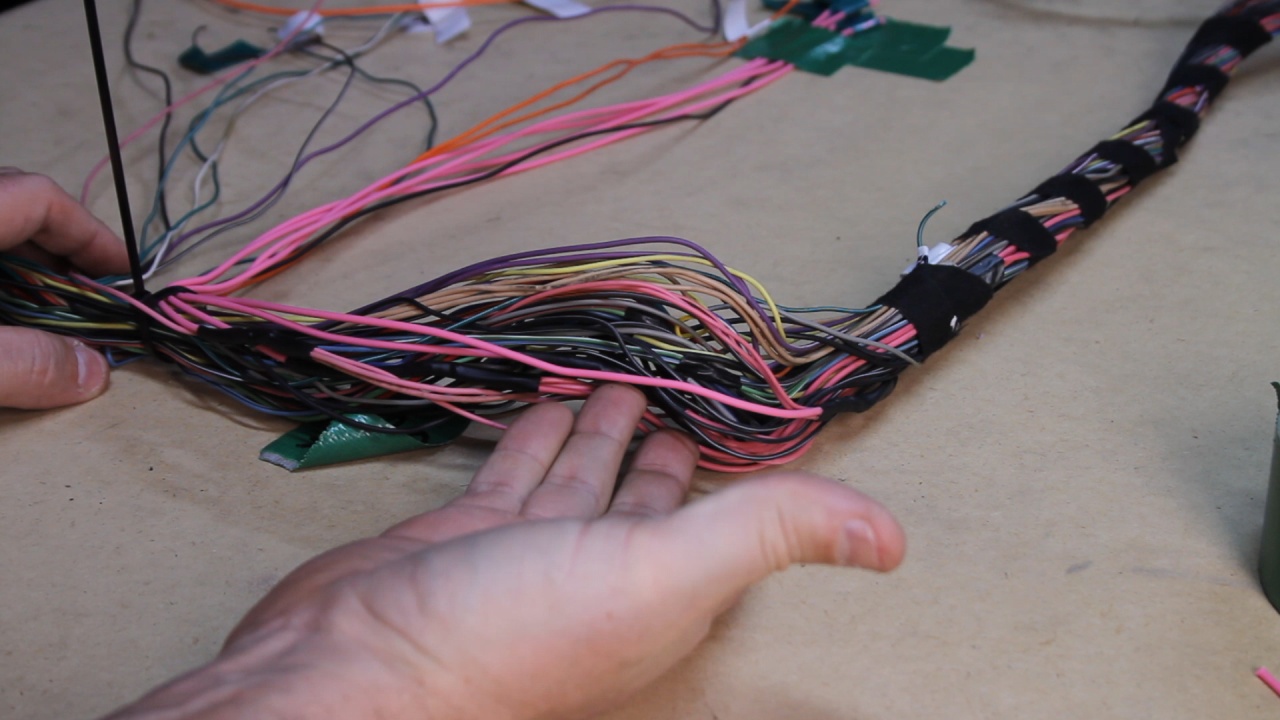
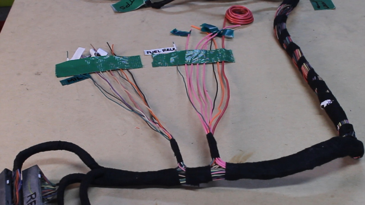
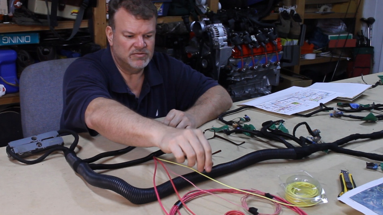
Getting close on completing the wiring harness! Here are a few shots of joining and extending some wires that will exit the wiring harness towards the new Fuse Block and Instrument connector.
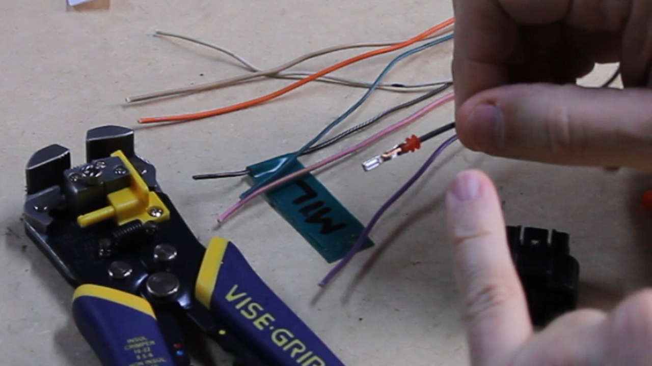
When I had completely removed all of the sensor connectors, I ended up with the three wires left in the stack that I had expected would be gone.
1) A Purple Wire - which is one of the rear O2 Sensor wires that I purposely left in the harness to be used for the Coolant Fan Relay trigger. This wire will need to be pinned back into the Blue PCM connector on Pin 42.
2) A Black Wire - This turned out to be a Ground wire that originally went to one of the Large connectors removed earlier (C100, C152, C153). I used this and extended it for use in my Instrument Connector. This I will try to get to next week.
3) A Gray Wire - This one was not expected. Turns out this was labeled on the Pinout chart with reference to the transmission and that is why I removed it from the PCN connector. This wire attaches to both the Transmission connector and the Temperature Sensor (We need this!!!). I re-pinned this back to Blue Pin 41.
For the Pink Wires, I joined and extended them to the Fuse Block location. These are the Keyed Positive wires for the Injectors, Coils, PCM, Check Engine Light, and MAF. I spread out along the harness.
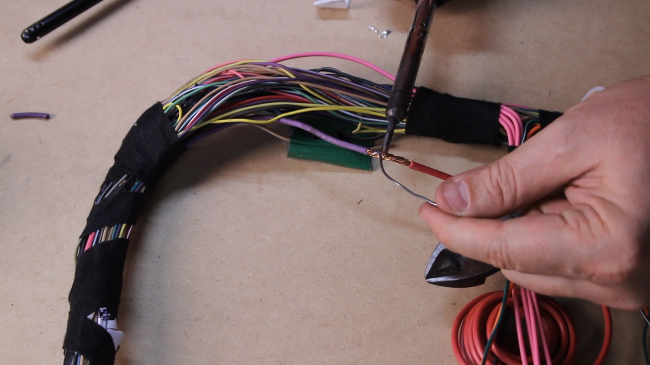
I also joined the Orange Wire (Battery Positive) with an extension that heads towards the Fuse Block and one additional wire going to the new Instrument connector to power the OBD2 port.
The 10 AWG Purple Wire is from the Starter and needs to be extended toward the new Fuse Block.
After about 7 revisions to my LS Wiring Harness Wiring Plan, I finally had something that I was comfortable with. In this photo, I have completed the physical wiring to match my plan.
Next time, I will be working on the wiring up the new Fuse Block and connecting my new Instrument Connector. Thanks for following along... Hop you are enjoying the ride!
When I had completely removed all of the sensor connectors, I ended up with the three wires left in the stack that I had expected would be gone.
1) A Purple Wire - which is one of the rear O2 Sensor wires that I purposely left in the harness to be used for the Coolant Fan Relay trigger. This wire will need to be pinned back into the Blue PCM connector on Pin 42.
2) A Black Wire - This turned out to be a Ground wire that originally went to one of the Large connectors removed earlier (C100, C152, C153). I used this and extended it for use in my Instrument Connector. This I will try to get to next week.
3) A Gray Wire - This one was not expected. Turns out this was labeled on the Pinout chart with reference to the transmission and that is why I removed it from the PCN connector. This wire attaches to both the Transmission connector and the Temperature Sensor (We need this!!!). I re-pinned this back to Blue Pin 41.
For the Pink Wires, I joined and extended them to the Fuse Block location. These are the Keyed Positive wires for the Injectors, Coils, PCM, Check Engine Light, and MAF. I spread out along the harness.
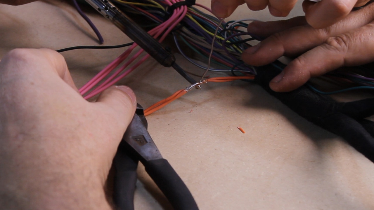
I also joined the Orange Wire (Battery Positive) with an extension that heads towards the Fuse Block and one additional wire going to the new Instrument connector to power the OBD2 port.
The 10 AWG Purple Wire is from the Starter and needs to be extended toward the new Fuse Block.
After about 7 revisions to my LS Wiring Harness Wiring Plan, I finally had something that I was comfortable with. In this photo, I have completed the physical wiring to match my plan.
Next time, I will be working on the wiring up the new Fuse Block and connecting my new Instrument Connector. Thanks for following along... Hop you are enjoying the ride!
Last edited by UcanDoIt2; May 8, 2017 at 10:16 PM.
Thread Starter
Teching In
Joined: May 2014
Posts: 39
Likes: 1
If interested in the details of the wire Joins and Extensions, this video is a better document of how I accomplished this. I also includes a discussion of how things are shaping up.
YouTube Channel: UCanDoIt2
https://www.youtube.com/watch?v=SX0Hg5pE9HE
YouTube Channel: UCanDoIt2
https://www.youtube.com/watch?v=SX0Hg5pE9HE
Last edited by UcanDoIt2; May 8, 2017 at 10:21 PM.


Thread Starter
Teching In
Joined: May 2014
Posts: 39
Likes: 1
Just wrapped up the LS Harness cleanup. I had created two groups of wires that exit the harness. The first group (on the left) is for all of the instrumentation and dash components. The second group (right) is all of the Power wires.
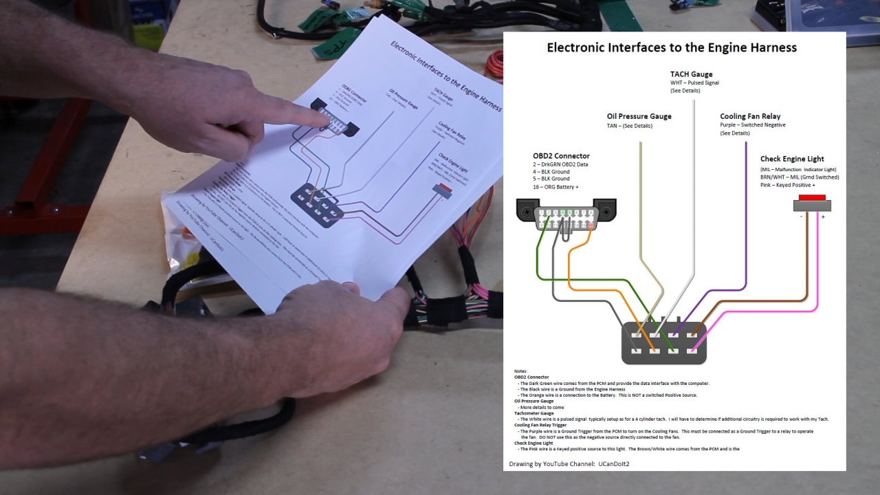
Here is a diagram that I created to document my plan for this section of the harness.
This page of the diagram Illustrates the Dash components (Check Engine Light, OBD2 Connector, Tach, and Oil Pressure). I needed to document this as it will be later in the build when it gets implemented. I will install these devices, then run their wires to the engine harness, then terminate them into a Male connector to what I will show you next.
I began with the Right hand group for the Gauges and Dash components by cutting the wires to the same length, then crimping on the proper terminals.
Then I plugged them into the custom 8 pin connector according to the drawing.
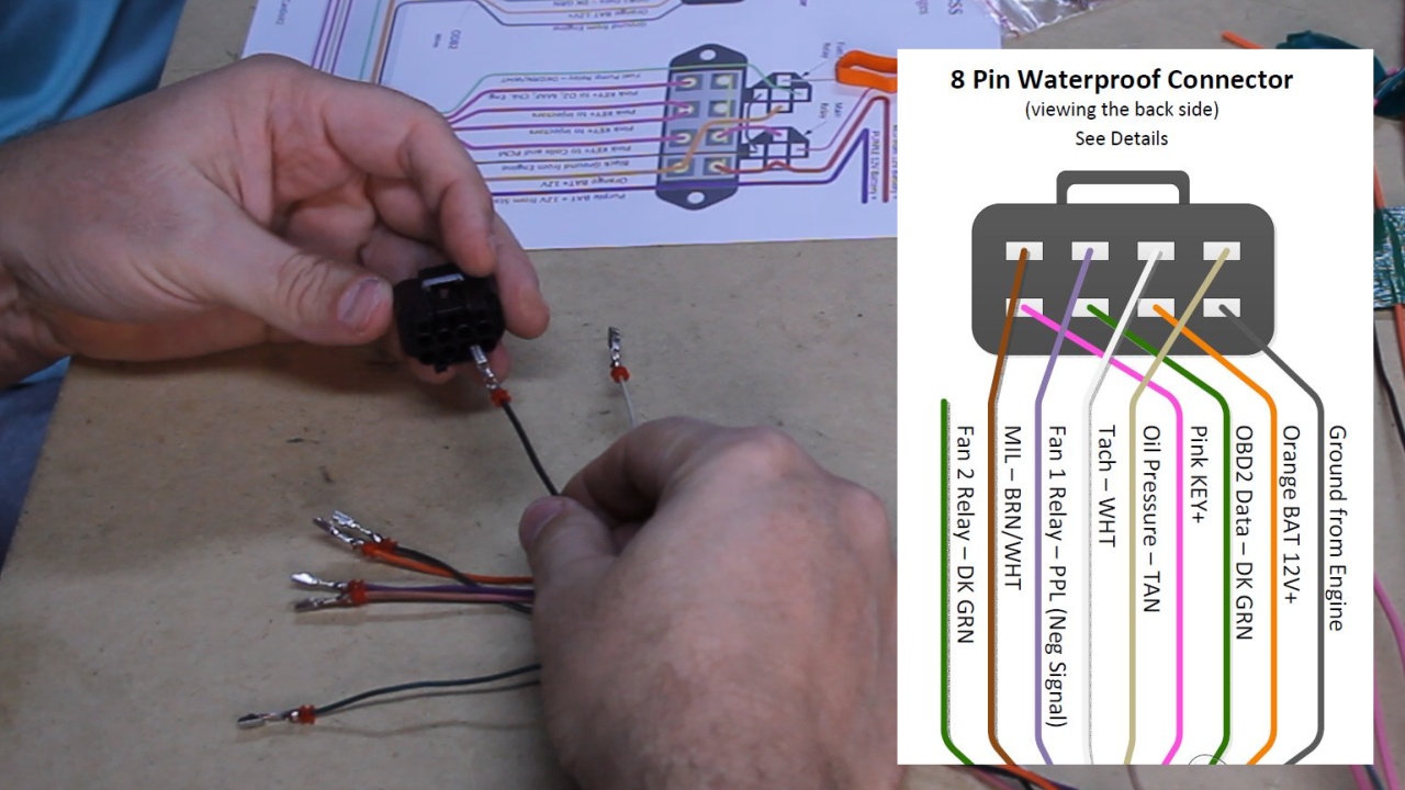
This a look at the completed Dash/Gauge connector
Next it was time to work on the Power related wires.
Here is the new 4 position Fuse Block with 2 Relay sockets installed.
Cut the wires to a common length, then added the terminals as per the plan. This required to group a few of the wires.
There is special requirements to create a separate #1 Fuse and to leave the brass connector for Fuses 2, 3 and 4.
Here both groups of wires are now complete. You can see that on the Power section, I have routed 4 wires back down and allowed to exit the loom. This created a cleaner look and these are the 4 Wires that are common when you are creating a 4 Wire Stand A Lone Hareness. These are the Starter Power, Battery Power, Keyed Power, and Fuel Pump Power.
It feels good to have this basically completed. With some conversation on my YouTube channel, I have decided to create a detailed drawing of how I am going to wire my Starter circuit. And I will go over that next time.
Thanks for following alone.
Here is a diagram that I created to document my plan for this section of the harness.
This page of the diagram Illustrates the Dash components (Check Engine Light, OBD2 Connector, Tach, and Oil Pressure). I needed to document this as it will be later in the build when it gets implemented. I will install these devices, then run their wires to the engine harness, then terminate them into a Male connector to what I will show you next.
I began with the Right hand group for the Gauges and Dash components by cutting the wires to the same length, then crimping on the proper terminals.
Then I plugged them into the custom 8 pin connector according to the drawing.
This a look at the completed Dash/Gauge connector
Next it was time to work on the Power related wires.
Here is the new 4 position Fuse Block with 2 Relay sockets installed.
Cut the wires to a common length, then added the terminals as per the plan. This required to group a few of the wires.
There is special requirements to create a separate #1 Fuse and to leave the brass connector for Fuses 2, 3 and 4.
Here both groups of wires are now complete. You can see that on the Power section, I have routed 4 wires back down and allowed to exit the loom. This created a cleaner look and these are the 4 Wires that are common when you are creating a 4 Wire Stand A Lone Hareness. These are the Starter Power, Battery Power, Keyed Power, and Fuel Pump Power.
It feels good to have this basically completed. With some conversation on my YouTube channel, I have decided to create a detailed drawing of how I am going to wire my Starter circuit. And I will go over that next time.
Thanks for following alone.
Last edited by UcanDoIt2; May 8, 2017 at 10:23 PM.

On The Tree

Joined: Aug 2016
Posts: 130
Likes: 9
I would like to thank you, as well as the LT1swap.com site, for putting this information in an easy to understand format. I'm in the process of an LS swap into a BMW and this was extremely helpful yesterday when I thinned the donor harness. Great job!
The donor engine, ECU, and harness I have came out of a 2007 Silverado Classic 4WD (DBW), and there were a few differences regarding the C2 block and a TAC module bundle in the wiring. All told though, these videos made it easy to find my way. Thanks again.
The donor engine, ECU, and harness I have came out of a 2007 Silverado Classic 4WD (DBW), and there were a few differences regarding the C2 block and a TAC module bundle in the wiring. All told though, these videos made it easy to find my way. Thanks again.
Thread Starter
Teching In
Joined: May 2014
Posts: 39
Likes: 1
So.... I thought I was going to be done with the wiring and put off thinking through where the 4 Power wires will connect to the Jeep. I ran across an interesting video that talked about the capability of the PCM Assisting in the starting of the engine and it sparked my attention. It turns out that my harness (2001) does not have this feature, but let me explain what it is.
Beginning in 2003, the Starter circuit passes through the PCM so that the computer can assist in the starting of the engine. As long as you hold the key in "Start" for at least 0.4 seconds, the PCM will continue to attempt to start the car until either 1) it starts, or 2) a specified amount of time has expired. I think that would have been pretty cool on this ole Jeep. But it just isn't going to happen.
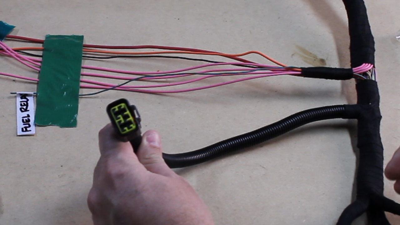
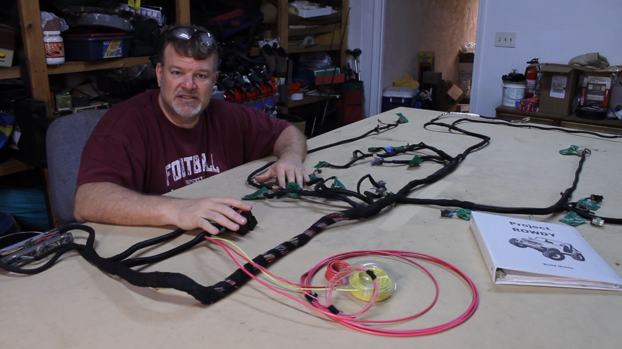
Meanwhile, my curiosity was at its peek and I began to think about the 4 Power wires and where exactly they will need to be connected in the Jeep, so I started to investigate. Here is what I found
In the photo above, there are two wires that I already know how they will be handled. The Yellow wire is my Fuel Pump Positive wire. It will be run back to the fuel tank and connect to the Fuel Pump. The Fuel Pump will most likely be locally Grounded. The Large Red Wire will be run to a junction block that comes straight from the Battery Positive. That takes care of 2 of the 4 wires.
Now for the Purple Starter wire and Pink Keyed Positive wire. For this I have studied the wiring diagram of the CJ7 Jeep that the engine will be installed.
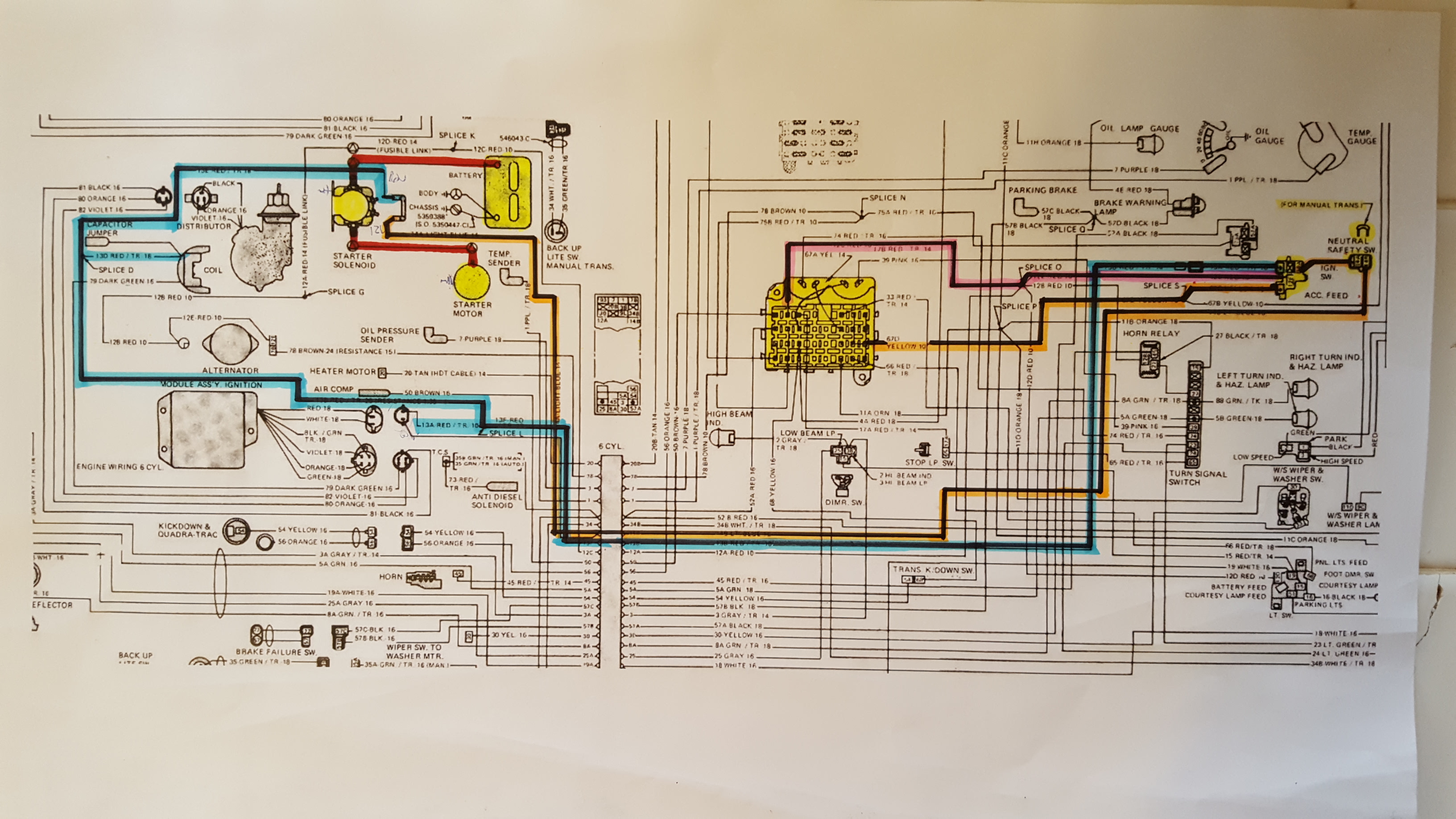
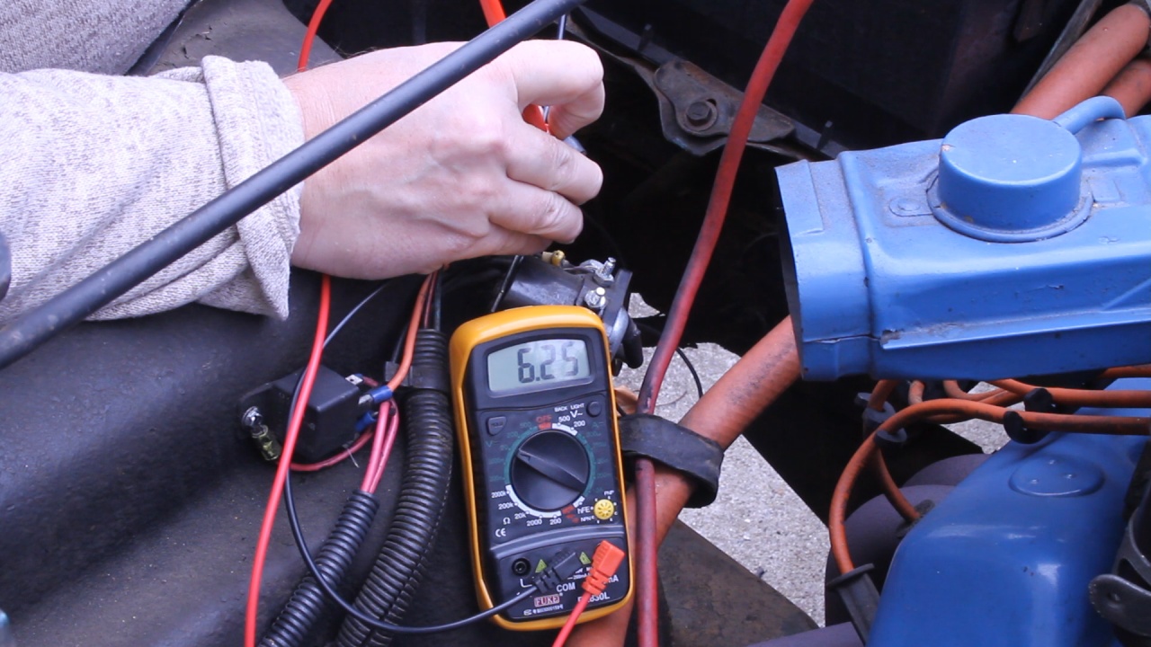
Both of these wires are a function of the ignition system and so studying the Ignition Switch was a good starting point. The Ignition Switch is located on the right side of the diagram. There is a Red with Tracer wire that appears to be the RUN+ (Keyed+, Highlighted in Blue) and a Light Blue wire (Start+, Highlighted in Orange). These wires run out to the Starter Solenoid. I should be able to test for 12V at the Solenoid and see if these are the wires that I need.
For some reason the Red/TR wire tested at 6.25 Volts and I not only cannot figure out why that would be, but a Keyed+ wire going to the Starter Solenoid doesn't make sense either. The Light Blue wire tested for 12V when the Key was turned to START, so that one is one that I need.
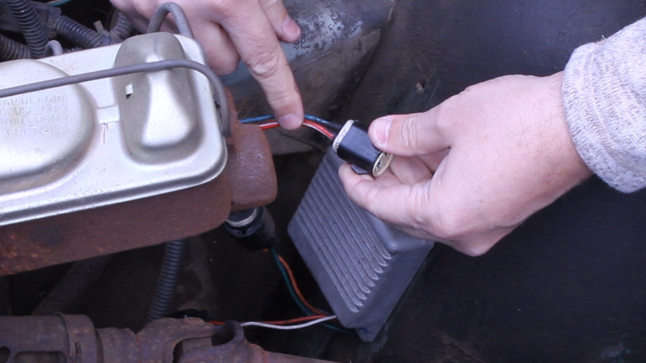
According to the wiring diagram, both of these wires have a splice and each went to a connector for the Ignition Module.
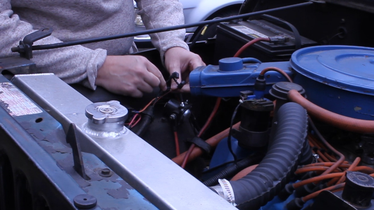
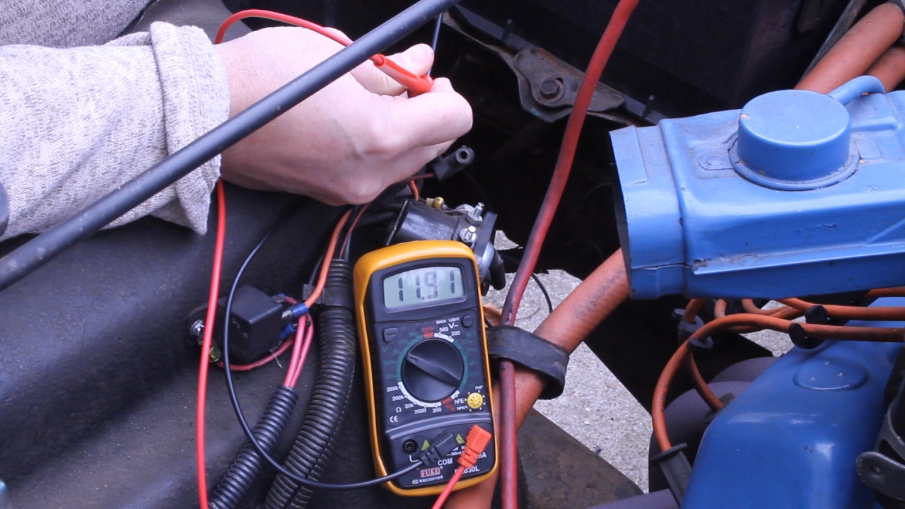
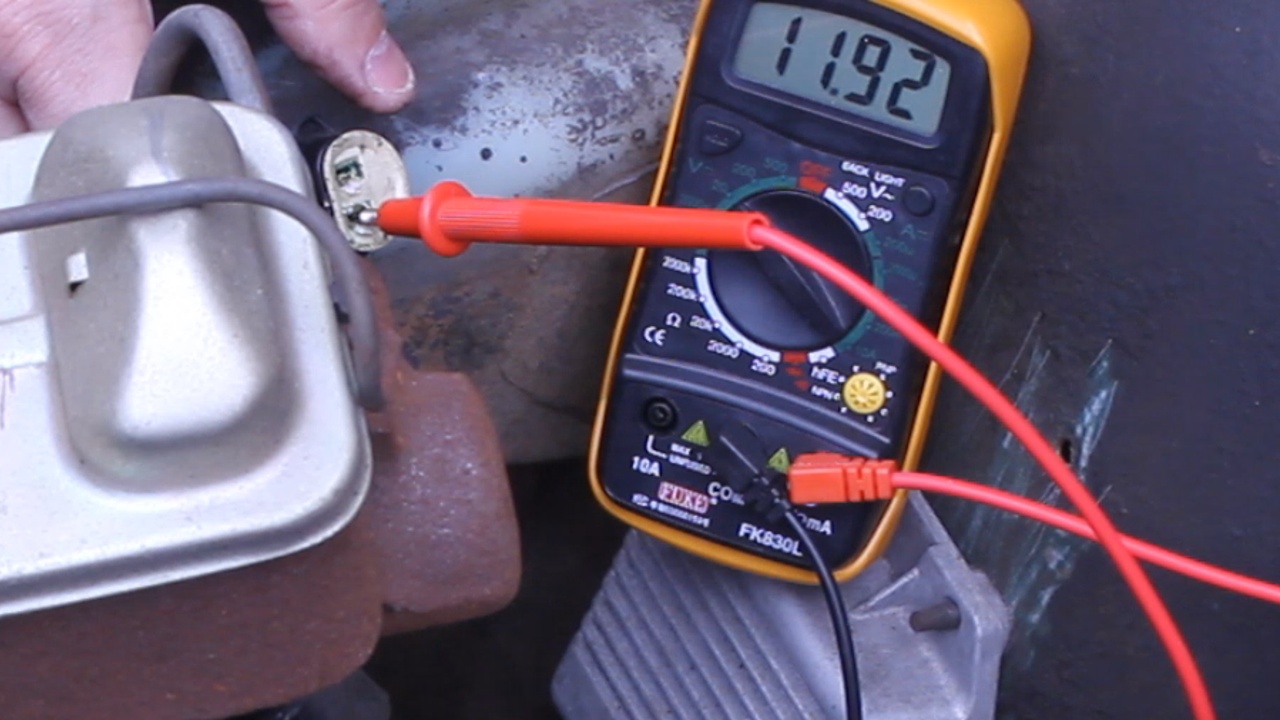
My battery is a little weak, but at this location, both of the wires tested out at 11.9 Volts. The Red/TR wire is hot when the ignition switch is in Run position and the Light Blue wire is hot when the ignition switch is in the Start position.
So this is where I will join the New Engine Harness to the existing ignition system. The Red/TR wire will connect to the PINK (Keyed+) wire and the Light Blue wire will be used to trigger a Starter Relay for the Purple (Start+) wire.
Next I will be beginning on some body work while I start to source a Dana 300 Transfer Case and order some adapters to glue the drive train together.
Talk to you soon!
Beginning in 2003, the Starter circuit passes through the PCM so that the computer can assist in the starting of the engine. As long as you hold the key in "Start" for at least 0.4 seconds, the PCM will continue to attempt to start the car until either 1) it starts, or 2) a specified amount of time has expired. I think that would have been pretty cool on this ole Jeep. But it just isn't going to happen.
Meanwhile, my curiosity was at its peek and I began to think about the 4 Power wires and where exactly they will need to be connected in the Jeep, so I started to investigate. Here is what I found
In the photo above, there are two wires that I already know how they will be handled. The Yellow wire is my Fuel Pump Positive wire. It will be run back to the fuel tank and connect to the Fuel Pump. The Fuel Pump will most likely be locally Grounded. The Large Red Wire will be run to a junction block that comes straight from the Battery Positive. That takes care of 2 of the 4 wires.
Now for the Purple Starter wire and Pink Keyed Positive wire. For this I have studied the wiring diagram of the CJ7 Jeep that the engine will be installed.
Both of these wires are a function of the ignition system and so studying the Ignition Switch was a good starting point. The Ignition Switch is located on the right side of the diagram. There is a Red with Tracer wire that appears to be the RUN+ (Keyed+, Highlighted in Blue) and a Light Blue wire (Start+, Highlighted in Orange). These wires run out to the Starter Solenoid. I should be able to test for 12V at the Solenoid and see if these are the wires that I need.
For some reason the Red/TR wire tested at 6.25 Volts and I not only cannot figure out why that would be, but a Keyed+ wire going to the Starter Solenoid doesn't make sense either. The Light Blue wire tested for 12V when the Key was turned to START, so that one is one that I need.
According to the wiring diagram, both of these wires have a splice and each went to a connector for the Ignition Module.
My battery is a little weak, but at this location, both of the wires tested out at 11.9 Volts. The Red/TR wire is hot when the ignition switch is in Run position and the Light Blue wire is hot when the ignition switch is in the Start position.
So this is where I will join the New Engine Harness to the existing ignition system. The Red/TR wire will connect to the PINK (Keyed+) wire and the Light Blue wire will be used to trigger a Starter Relay for the Purple (Start+) wire.
Next I will be beginning on some body work while I start to source a Dana 300 Transfer Case and order some adapters to glue the drive train together.
Talk to you soon!
Last edited by UcanDoIt2; May 8, 2017 at 10:25 PM.