


Cam Degree Help
I was in the middle of a cam install when I realized with my timing set I'm not really able to see for certain the crank gear timing dot it's a Cloys Hex set. There are multiple marks that are visible underneath the dampner but nothing is certain. I didn't mark the crank before removing the old cam so now I am guessing with the 'dot-to-dot' method on the new cam.
Anyway I should do a cam degree anyway so the good is now I'm definately doing one now. Here's my question after I find TDC with the dial indicator as directed in the cam degree guide I set my degree wheel to 0 and then make certain that when my #1 intake lifter is at max lift it is 115 degree (that's the LSA on the cam card) advanced of the 0 from TDC on my #1 piston and I have my cam properly installed.
Assuming I am in the blind on where my crank dot is which I practically am will this method work fine? This may be a dumb question but if after I a degree and get it adjusted correctly is it still possible I am on wrong piston stroke? If so what's the best way to fix this.
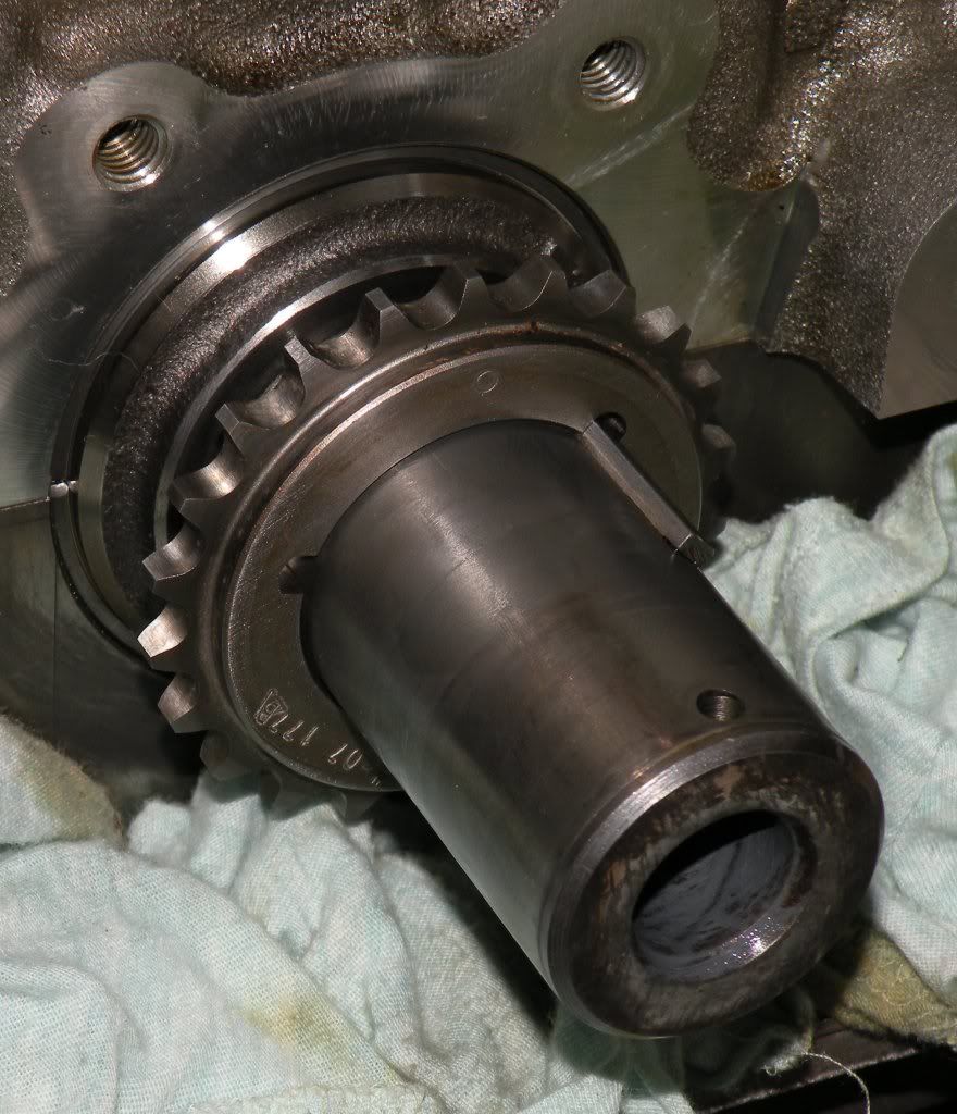
Yes it will work. On the Cloyes, there are three shaped keys for crank installation. So first question is which do you have installed? One is square on top, one is rounded and one it triangular if I remember correctly. If the oil pump driver is on, you should still be able to see the edge of the mark if you look closely. I have photo's of mine at home.
I'm not really certain which one they installed it on. I will look again this afternoon and see if I can make out which one it is. It's not really the oil pump that's blocking view more the dampner but I may be able to pull that off with out taking the pump out.
Will it matter if I can't find which one it's the crank gear is installed on?
One thing I can see is it looks like the builder put a small tick on the base of the crank gear that is visible clearly it's a mark made by hand. This may have been his notation for TDC I'm not sure for now I'm using that mark to line up my cam gear dot and degreing from there.
I have photo's I took that may help. I took some with the oil gear off and some with them on. That may help you find what you need to identify for marks. With the oil pump in place, it will be impossible to see which they have it on but it is likely 99% that they put it on the zero (no advance or retard) position such that the hex-adjust movement would be around the true zero.
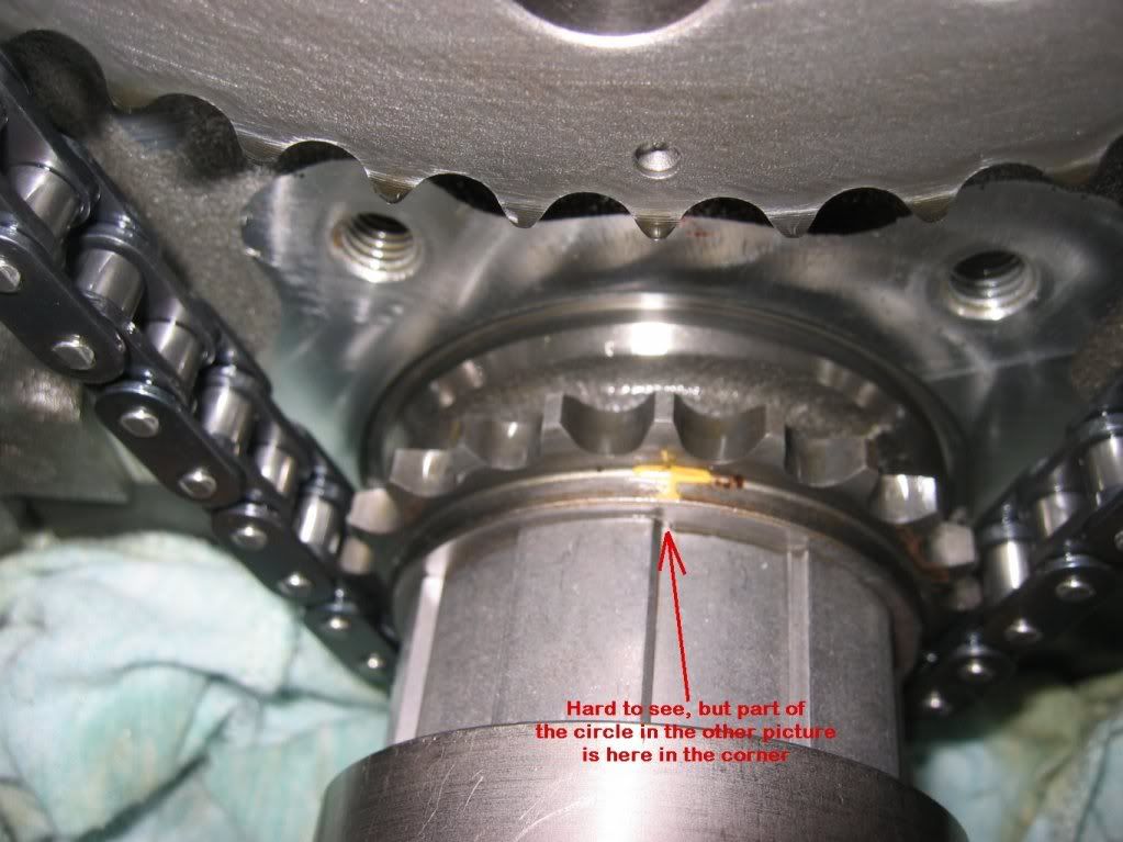
Hopefully these help. The first photo shows two of the keyways in the crank sprocket. The one I used is the "standard" position, i.e., no advance or retard. Once the oil driver goes in place, a lot of the alignment mark gets covered so I marked the tooth with yellow paint so I could find it at a glance while degreeing the cam. Hope these help.
I think I've got it right now. I used my degree kit and found #1 TDC at this point I set my degree wheel with the 0(TDC) pointed to 12oclock and mounted my cam gear with the dot pointed to 12oclock as well. I then mounted my dial indicator onto my #1 intake valve lifter and found intake centerline to be right at 114 the same as my cam card.
Also after doing all that I saw your pictures so I rotated my cam gear dot down to 6oclock and looked real hard with a light to see that crank gear circle and sure enough there it was at 12oclock dot-dot.
So I think I've got the timing set right now my only questions left are.
1.) does this assure me that everything is set on the correct piston stoke
2.) I'm not really sure but I it's interesting because the intake lifter starts lifting right before the pistons reaches TDC on the exhaust stoke and finally closes when the piston is half way through the compression stoke is this normal doesn't seem right but I've never looked for this before.
Thanks for the pictures man helped a lot!
Thanks for the pictures man helped a lot!
Yes, intake can start to open before TDC on exhaust stroke while the exhaust valve is still open. If you have the 0.006" numbers on the car it will tell you where the intake open point is. It is usually something like 2 degrees BTDC (before top dead center) and close 20 deg ABDC (after bottom dead center).
Trending Topics
I looked at my cam card and the .050 INT:2 BTDC and 50 ABDC.
So since the wheel is attached I turned it over and hmm I must have done something wrong because the dial indicator on the lifter starts moving at 30* BTDC reaches max lift at 114* ATDC and no lift 100* after ABDC.
Here's what I'm reading off the degree wheel I may be doing this wrong.
-Degree wheel set TDC 0* at 12oclock #1 piston in TDC checked by dial indicator
-Rotate Crank #1 Intake Lifter reaches max lift at 114* ATDC which is Intake Center Line for this Cam
-Intake lifter returns to no lift postion at 280* on the crank degree wheel 100* ABDC
-After rotating wheel one full rotation to return to the intake stroke the intake lifter begins raising the dial indicator again at 330* on the wheel 30* BTDC
There something in the process I must not be grasping fully yet because like I said it's dot-dot so I don't really see it being that far off.
I just thought of this but when I check the degree wheel for open/close BTDC and ABDC am I suppose to wait until the lifter has reached full travel or is it at a set distance measured by the dial indicator.
Thanks again
LS1 Tech Stories
The Best V8 Stories One Small Block at Time

Topdon ONE vs. Artidiag 800 BT2: Which is the Diagnostic Tablet For You?
Pouria Savadkouei
Gas Monkey Built a 6-Wheel Ferrari Testarossa With a Corvette LT4 Engine
Verdad Gallardo
7 Most Reliable High-Performance Engines GM Has Ever Built
Verdad Gallardo
Amazing '71 Camaro Restomod Is Modern Muscle Car Under the Skin
Verdad Gallardo
6 Common C5 Corvette Failures and What's Involved In Repairing Them
Pouria Savadkouei
Retro Modern Bandit Pontiac Trans AM Comes With Burt Reynolds' Autograph
Verdad Gallardo
Top 10 Greatest Cadillac V Series Performance Models Ever, Ranked
Pouria Savadkouei
Top 10 Most Powerful Chevy Trucks Ever Made!

Hennessey's New Supercharged Silverado ZR2 Has 700 HP
Verdad Gallardo I think I understand it now.
My cam card say @ .050 INT: 2* BTDC =Open
: 50* ABDC= CLOSE
This means that after .050 of lift my degree wheel should be at 2* BTDC
and
.050 prior to the lifter reaching bottom of travel my degree wheel should 50 ABDC
If that is correct then my cam is installed and matches my cam card. I hope that's correct needless to say.
Yes, if you set your dial indicator to zero with the lifter against the cam base circle as the lifter starts to rise stop at 0.050" and you should get the same value as the cam card. Then when the valve is closing again stop at 0.050" prior to full valve close and you should get the closing value. This is a good double check on the intake centerline method and since all the tools are in place and you already have the TDC of the piston it only takes a couple of minutes.