


crank trigger wheel on crank relationship
Is there an identifier on the crank trigger wheel that presses on the crank that tells where TDC of #1 would be or something of the like?
I'm using a 0411 to run a non ls engine. I want the high res ignition so I'm going to use the ls1 triggers and sensors but I'm not sure how to orient the wheel on the crank.
I have a crank trigger wheel sitting right in front of me so if someone needs a picture to explain I can post a pic of it.
Thanks.
using this thread and my wheel...I found it.
https://ls1tech.com/forums/pcm-diagn...ank-scope.html
TDC of #1 is thru the alignment hole.
guess I should have searched more.
https://ls1tech.com/forums/pcm-diagn...ank-scope.html
TDC of #1 is thru the alignment hole.
guess I should have searched more.
Thanks man for posting your scope of the sensor outputs.  It has been a huge timesaver.
aligned in what respect?
I'm going to be using a single wheel like the L21 but closer to the size of the ls1 dia. This is because I'm running it externally between my blower hub and pulley and need room for the sensor to pickup.
Do you know if the sensor goes high when the ring is "high" or does the sensor go low when the ring goes "high". I haven't figured out which ring the ls1 reads off yet, but I will as soon as my sensor comes in tomorrow. I bought a sensor for the L21 since its shorter than the ls1 and will mount external much easier.
From what I understand the only engine that "needs" both wheels is the Northstar which has two crank position sensors.
**edit- I was wrong on the GM L21 wheel. It is a two wheel config. I'll find out tomorrow if this is necessary.
It has been a huge timesaver.aligned in what respect?
I'm going to be using a single wheel like the L21 but closer to the size of the ls1 dia. This is because I'm running it externally between my blower hub and pulley and need room for the sensor to pickup.
Do you know if the sensor goes high when the ring is "high" or does the sensor go low when the ring goes "high". I haven't figured out which ring the ls1 reads off yet, but I will as soon as my sensor comes in tomorrow. I bought a sensor for the L21 since its shorter than the ls1 and will mount external much easier.
From what I understand the only engine that "needs" both wheels is the Northstar which has two crank position sensors.
**edit- I was wrong on the GM L21 wheel. It is a two wheel config. I'll find out tomorrow if this is necessary.
Last edited by cajundragger; May 9, 2012 at 10:40 AM.
TECH Senior Member


Joined: Apr 2002
Posts: 6,080
Likes: 17
From: So.Cal.
Hey you're welcome.
I meant a pic of how you have it clocked/aligned wrt to something on the crank (like the crank sprocket dot or the keyway).
The LS1 24x CKP sensor reads both wheels and if they match (i.e. are the inverse of each other) it produces a single signal as shown on the waveform (i.e. the sensor has electronics in it).
I don't have it mounted on the engine yet. I won't have it mounted for ~6 weeks as the engine is still at the machine shop but I'm trying to work on all the engine-computer interfaces so I will be ready.
The engine is a 1948 Cadillac Flathead 346ci. with a 4-71 roots blower. Going in a '31 model A.
on a small block chevrolet you would center the alignment hole directly over the keyway and I assume(will know tomorrow) center the sensor over this alignment hole as well. I'm not sure if there is a forward or reverse latency in the sensor.
OR
the sensor has to at least be centered over the alignment hole when #1 isTDC,either true TDC or in overlap doesn't matter..
Tomorrow I will mount my wheel and the sensor in a lathe with a dual channel Oscope so I can precisely measure any and all variables. If you have anything your looking for LMK.
so far I'm wanting to measure..
1.) general wave pattern from a stock sensor(make sure it matches your data) and wave pattern from a few wheels that I had water jetted and trued on a lathe
2.) standoff acceptance of the sensor to the wheel. so far I think it will be in the .001"-.020" range.
3.) alignment as far as too far forwards or back from the wheel. I think the wheel is not supposed to be centered on the sensor but we'll see.
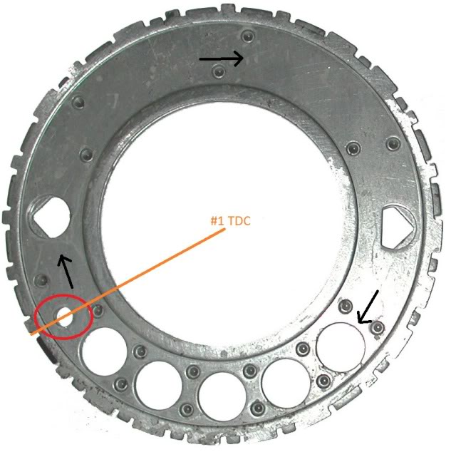
I marked direction the wheel spins, the alignment hole and where #1 TDC is from what I know right now. If my results from tomorrow change any of these I'll post up an edited version.
is there a place where this thread is better suited? I wasn't real sure where to put it...
The engine is a 1948 Cadillac Flathead 346ci. with a 4-71 roots blower. Going in a '31 model A.
on a small block chevrolet you would center the alignment hole directly over the keyway and I assume(will know tomorrow) center the sensor over this alignment hole as well. I'm not sure if there is a forward or reverse latency in the sensor.
OR
the sensor has to at least be centered over the alignment hole when #1 isTDC,either true TDC or in overlap doesn't matter..
Tomorrow I will mount my wheel and the sensor in a lathe with a dual channel Oscope so I can precisely measure any and all variables. If you have anything your looking for LMK.
so far I'm wanting to measure..
1.) general wave pattern from a stock sensor(make sure it matches your data) and wave pattern from a few wheels that I had water jetted and trued on a lathe
2.) standoff acceptance of the sensor to the wheel. so far I think it will be in the .001"-.020" range.
3.) alignment as far as too far forwards or back from the wheel. I think the wheel is not supposed to be centered on the sensor but we'll see.
I marked direction the wheel spins, the alignment hole and where #1 TDC is from what I know right now. If my results from tomorrow change any of these I'll post up an edited version.
is there a place where this thread is better suited? I wasn't real sure where to put it...
I have my Waterjet wheel running on the lathe with a sensor and Oscope attached and I'm getting a signal that is visually the same as the stock wheel.
Think if I can get an Rpm reading out of the computer then it's working?
I'm not sure if my signal is exactly correct, but it appears to be.
Think if I can get an Rpm reading out of the computer then it's working?
I'm not sure if my signal is exactly correct, but it appears to be.
Trending Topics
LS1 Tech Stories
The Best V8 Stories One Small Block at Time

6 Common C5 Corvette Failures and What's Involved In Repairing Them
Pouria Savadkouei
Retro Modern Bandit Pontiac Trans AM Comes With Burt Reynolds' Autograph
Verdad Gallardo
Top 10 Greatest Cadillac V Series Performance Models Ever, Ranked
Pouria Savadkouei
Top 10 Most Powerful Chevy Trucks Ever Made!

Hennessey's New Supercharged Silverado ZR2 Has 700 HP
Verdad Gallardo
Coachbuilt N2A Anteros Is an LS2-Powered C6 Corvette In Italian Clothes
Verdad Gallardo
Awesome K5 Blazer Restomod Comes With C7 Corvette Power
Verdad Gallardo
10 Camaros You Should Never Buy

10 LS Engine Myths That Refuse to Die
Verdad Gallardo
Teching In

Joined: Jan 2019
Posts: 46
Likes: 0
Been several years since this was posted and I'd like some clarification if possible.
If the alignment hole is centered over the snout keyway with #1 at TDC and the sensor is at the top as positioned in the LS block, then doesn't that mean that the alignment hole is rotated quite a ways past the sensor at TDC? (SBC snout keyway is not at the top with #1 at TDC but closer to being aligned with the centerline of #1 cylinder, right?)
Just trying to find out what's really going on here.
Jim