
NA 'street' LS2 403 build - "From Crate to Dyno"


 01-10-2010, 01:28 PM
#43

Very impressed Helicoil....hell, I was super impressed with your Procharged build and followed it closely. Have you ever considered building engines for more than just a hobby? I'd gladly pay to have one of your works of art in my engine bay as I'm sure many others would too.
I'd also suggest looking into the Circle D 230MM....it has performed very well in my baby setup. 5000 stall speed and excellent street manners. Give Chris a shout and ask him about it.
I'd also suggest looking into the Circle D 230MM....it has performed very well in my baby setup. 5000 stall speed and excellent street manners. Give Chris a shout and ask him about it.
Last edited by 99Hawk262; 01-10-2010 at 01:38 PM.
01-10-2010, 02:15 PM
#45
TECH Resident

FYI - GM went with the larger holes in the cam bearings when they went with VVT and the need to feed oil to the cam phaser through the #2 cam journal.
01-10-2010, 08:04 PM
#48
Thanks all.
The Procharger was fun, but had its own issues, like too much power. lol. The car wasn't legal for 9's and I didn't want to take it there. It only has 5000 miles on it, so a full roll cage really isn't an option in this one. I just got a little carried away with it.....also the cooling issues were a turn off. I like my A/C. The driveline in the car really wasn't suited for 9's either, more like 10's. So it just made sense to slow it down. I could have pulley'd it down....but I had someone who was really interested in the engine and I was eyeballing another car I wanted. It was fun to try and put it in the 9's and once I did I lost interest. NA is fun and a little more reliable and better suited for this car.
I do probably 8-10 completes a year and several sets of heads, some bore/hone jobs, balance jobs, etc. I really do enjoy it. I try to pick and choose the ones that interest me. I am not in position to do it full time.
That is the second recommendation for a Circle D, that is looking like the way to go. I will call Chris when I ready in a couple of weeks and go over my combo, I was thinking about a SS3600 from Yank, only because I am not up on the different converters out there. I figured this one would drive like I wanted around town.
Thanks again!
Ahh, there you go, that makes perfect sense.
Thanks for that.
I had thought about it, but now knowing the differences (without the VVT), there really is no point to. I just ordered the bearings for a 2004/5 Vette application and figured someone would chime in after I posted pictures, if not I would have done a bit more research when I got the time. I was pretty comfortable they were fine as they were the same ones in an iron LQ4 in the shop and my original LS1
Very impressed Helicoil....hell, I was super impressed with your Procharged build and followed it closely. Have you ever considered building engines for more than just a hobby? I'd gladly pay to have one of your works of art in my engine bay as I'm sure many others would too.
I'd also suggest looking into the Circle D 230MM....it has performed very well in my baby setup. 5000 stall speed and excellent street manners. Give Chris a shout and ask him about it.
I'd also suggest looking into the Circle D 230MM....it has performed very well in my baby setup. 5000 stall speed and excellent street manners. Give Chris a shout and ask him about it.
lol. The car wasn't legal for 9's and I didn't want to take it there. It only has 5000 miles on it, so a full roll cage really isn't an option in this one. I just got a little carried away with it.....also the cooling issues were a turn off. I like my A/C. The driveline in the car really wasn't suited for 9's either, more like 10's. So it just made sense to slow it down. I could have pulley'd it down....but I had someone who was really interested in the engine and I was eyeballing another car I wanted. It was fun to try and put it in the 9's and once I did I lost interest. NA is fun and a little more reliable and better suited for this car.I do probably 8-10 completes a year and several sets of heads, some bore/hone jobs, balance jobs, etc. I really do enjoy it. I try to pick and choose the ones that interest me. I am not in position to do it full time.
That is the second recommendation for a Circle D, that is looking like the way to go. I will call Chris when I ready in a couple of weeks and go over my combo, I was thinking about a SS3600 from Yank, only because I am not up on the different converters out there. I figured this one would drive like I wanted around town.
Thanks again!
Thanks for that.
I had thought about it, but now knowing the differences (without the VVT), there really is no point to. I just ordered the bearings for a 2004/5 Vette application and figured someone would chime in after I posted pictures, if not I would have done a bit more research when I got the time. I was pretty comfortable they were fine as they were the same ones in an iron LQ4 in the shop and my original LS1
01-12-2010, 06:59 AM
#51

Very cool thread. Awesome pics and info. You have a lot of neat toys and from the looks of it, this combo will be nothing short of amazing. Give me a call when you are ready and I can go over some options for you. Looking forward to talking to you soon.
713-895-8834
Chris
713-895-8834
Chris
01-17-2010, 02:09 PM
#52
Thanks Circle D, we'll do.
Time to add some more pics. Worked on it some more this week. Didn't get as much done as I hoped but I did work on the rods, ie measured and weighed them.
The Compstar stuff is very nice for the money, all but two measured dead on BOTH on the Big and Small ends. The two that were off, were off by tenths, nothing to be excited about. Their weights are always very, very close, even on the BBC stuff.
I did find it took about 82 ft. lbs of torque to get a solid .005" stretch on the ARP rod bolts though.
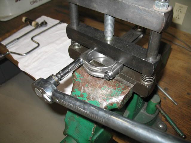
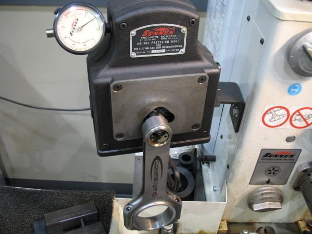
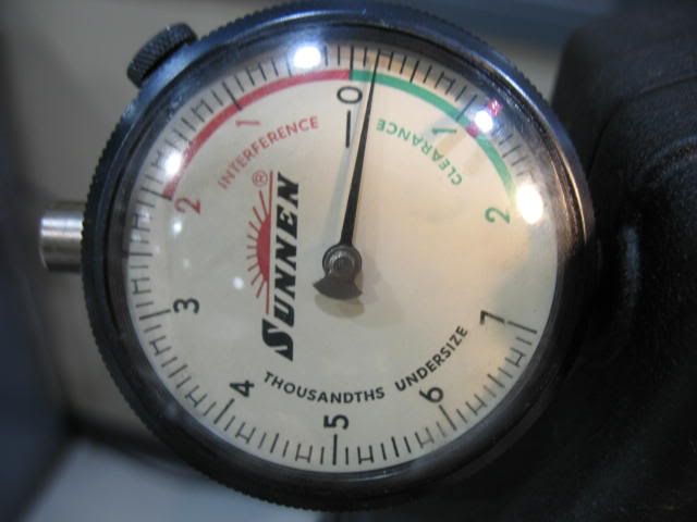
The small end of the rods measured about .0007" - .0008" tenths out of the box, I opened them up slightly to about .0009" - .001"
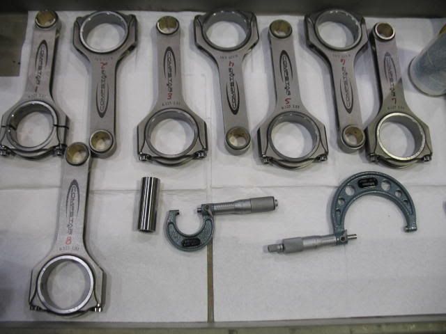
There was one out of the bunch that was a couple tenths big on the Big end and one that was a tad small on the Big end.
Time to add some more pics. Worked on it some more this week. Didn't get as much done as I hoped but I did work on the rods, ie measured and weighed them.
The Compstar stuff is very nice for the money, all but two measured dead on BOTH on the Big and Small ends. The two that were off, were off by tenths, nothing to be excited about. Their weights are always very, very close, even on the BBC stuff.
I did find it took about 82 ft. lbs of torque to get a solid .005" stretch on the ARP rod bolts though.
The small end of the rods measured about .0007" - .0008" tenths out of the box, I opened them up slightly to about .0009" - .001"
There was one out of the bunch that was a couple tenths big on the Big end and one that was a tad small on the Big end.
01-17-2010, 02:25 PM
#53
After sizing and weighing the rods which were very close to the weights on the card in the box I was able to get a total bobweight on all the rotating and reciprocating parts.
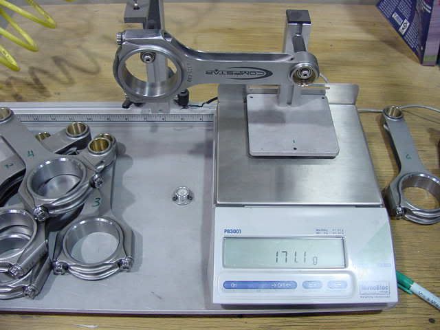
Rod Big - 455 grams
Rod Small - 171 grams
Piston - 424 grams
Piston Pin - 121 grams
Piston Rings w/ oil support rail - 42 grams
Rod insert - 45 grams
Piston Pin locks - 4.4 grams
Oil - 6 grams
This gave me a bobweight of 1768 grams.
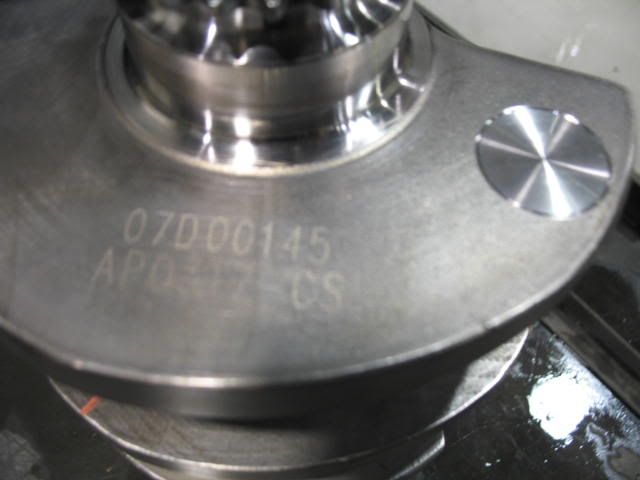
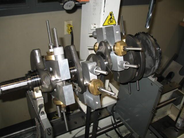
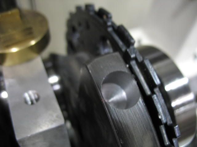
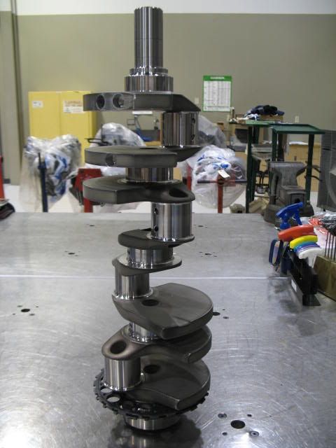
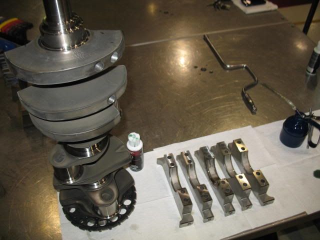
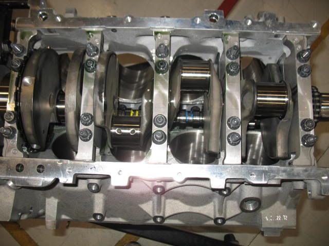
I then built it the weights and put the crank in the balancer. One thing I noticed different than the last 403 I did was this Compstar crank didn't have any Mallory (heavy metal) in it. The previous one had two 1" slugs in it, one in each end. It appears they have re-shaped the counterweights, adding the metal to the crank, probably cheaper for them.
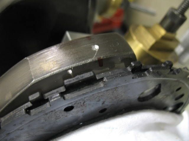
Here is a picture of the last one. Notice the Mallory in the end counterweight, it can get quite pricey, so I am sure they (Callies) figured out how to avoid using it.
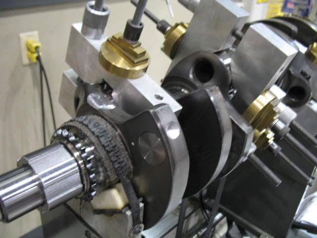
Here is my current 4.0" Callies Compstar with the bobweights on it and in the balancer.
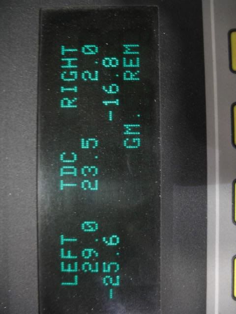
And here is what it came up after the first spin. -112 grams on the snout end and minus -31.5 grams on the back.
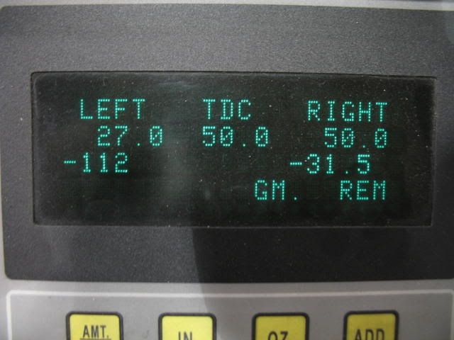
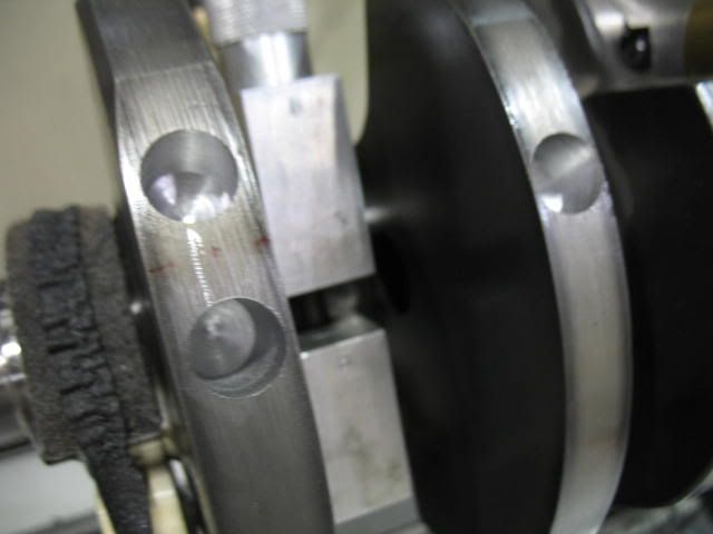
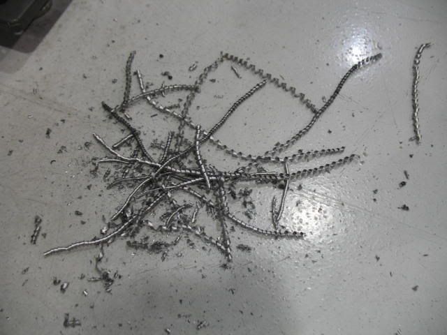
The 112 grams will take some drilling, actually about 3 holes, two holes in the first counterweight and 1 in the second counterweight back. They ended up being about .500" to .625" deep. The rear needed 1 hole about .350" deep and a kiss in another spot.
Second spin, getting closer.....
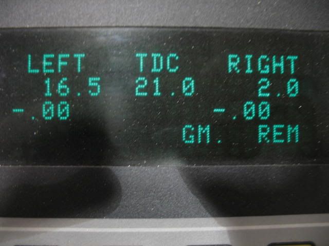
Done.
Rod Big - 455 grams
Rod Small - 171 grams
Piston - 424 grams
Piston Pin - 121 grams
Piston Rings w/ oil support rail - 42 grams
Rod insert - 45 grams
Piston Pin locks - 4.4 grams
Oil - 6 grams
This gave me a bobweight of 1768 grams.
I then built it the weights and put the crank in the balancer. One thing I noticed different than the last 403 I did was this Compstar crank didn't have any Mallory (heavy metal) in it. The previous one had two 1" slugs in it, one in each end. It appears they have re-shaped the counterweights, adding the metal to the crank, probably cheaper for them.
Here is a picture of the last one. Notice the Mallory in the end counterweight, it can get quite pricey, so I am sure they (Callies) figured out how to avoid using it.
Here is my current 4.0" Callies Compstar with the bobweights on it and in the balancer.
And here is what it came up after the first spin. -112 grams on the snout end and minus -31.5 grams on the back.
The 112 grams will take some drilling, actually about 3 holes, two holes in the first counterweight and 1 in the second counterweight back. They ended up being about .500" to .625" deep. The rear needed 1 hole about .350" deep and a kiss in another spot.
Second spin, getting closer.....
Done.
01-17-2010, 03:23 PM
#54
An update - outstanding  And more of those toys
Couple of questions if I may:
1. You added 500 to your totals to come up with bobweight - curious why this was done
2. You stated: The small end of the rods measured about .0007" - .0008" tenths out of the box, I opened them up slightly to about .0009" - .001" Could you elaborate on this?
This thread rocks!!
And more of those toys Couple of questions if I may:
1. You added 500 to your totals to come up with bobweight - curious why this was done
2. You stated: The small end of the rods measured about .0007" - .0008" tenths out of the box, I opened them up slightly to about .0009" - .001" Could you elaborate on this?
This thread rocks!!
01-17-2010, 04:23 PM
#55
01-17-2010, 07:51 PM
#56
An update - outstanding And more of those toys
Couple of questions if I may:
1. You added 500 to your totals to come up with bobweight - curious why this was done
2. You stated: The small end of the rods measured about .0007" - .0008" tenths out of the box, I opened them up slightly to about .0009" - .001" Could you elaborate on this?
This thread rocks!!
And more of those toys Couple of questions if I may:
1. You added 500 to your totals to come up with bobweight - curious why this was done
2. You stated: The small end of the rods measured about .0007" - .0008" tenths out of the box, I opened them up slightly to about .0009" - .001" Could you elaborate on this?
This thread rocks!!
This whole hobby is about toys isn't it. 
I'll try to answer.....
1. The bobweights are computed in this manner. Add up all the reciprocating items (Pistons, piston pins, rings, locks, small end of the rod) and multiply by 2, since there are two rod throws on each crank journal. Next multiply it by 50% (the balance factor used), some may use 51%-54% on high RPM stuff, but it really has no benefit here. That would be called an 'overbalanced' assembly. The theory is the higer the RPM, the more the reciprocating parts pull on the crank, so you overbalance the crank to account for the torsional loads that are being exerted on it. It is all theory really, as there is no way to verify the 'number' needed to compensate for this. I guess you just read your bearings upon a teardown - race car stuff. etc. Anyway, next figure the rotating weight. This is the rod bearing inserts and the Big end of the rod. Then again multiply by 2 (two rod throws). Don't forget to add the oil weight to this number. Then you have your rotating weight.
Now add the rotating weight and the reciprocating weight together. This equals the bobweight. Most balancers I have seen compute this number for you, you just plug in the individual weights, the rest is magic.
2. I like things that I am going to, or that are going to get abused right away to be on the 'looser' side. .001" on the clearance between the pins and the bronze bushings on the rods work well, especially when the heat gets turned up on the pistons (ie N20, boost, etc.) Much less likely to scuff and cause a problem. Really the .0008" they came at would work fine. I am just **** and can't run anything 'out-of-the-box' without massaging it.
This is an area where engine builders may have their own preferences. I know if this was going to be a vacuum assisted crankcase (engine driven vacuum pump with over 10"Hg) I would run them looser, .0013"-.0015''.Hoping sooner, much sooner than that. I always hate to put a deadline on projects like this that I do for myself. Something always seems to get in the way. But I know it won't be running until the weather warms up a bit. I'd like to see it being re-installed late Feb, early March. Depends on winter I guess. Engine will be done in a couple of weeks.
01-17-2010, 08:25 PM
#57
Yes, more toys, they are almost as much fun as doing the build. This whole hobby is about toys isn't it.
I'll try to answer.....
1. The bobweights are computed in this manner. Add up all the reciprocating items (Pistons, piston pins, rings, locks, small end of the rod) and multiply by 2, since there are two rod throws on each crank journal. Next multiply it by 50% (the balance factor used), some may use 51%-54% on high RPM stuff, but it really has no benefit here. That would be called an 'overbalanced' assembly. The theory is the higer the RPM, the more the reciprocating parts pull on the crank, so you overbalance the crank to account for the torsional loads that are being exerted on it. It is all theory really, as there is no way to verify the 'number' needed to compensate for this. I guess you just read your bearings upon a teardown - race car stuff. etc. Anyway, next figure the rotating weight. This is the rod bearing inserts and the Big end of the rod. Then again multiply by 2 (two rod throws). Don't forget to add the oil weight to this number. Then you have your rotating weight.
Now add the rotating weight and the reciprocating weight together. This equals the bobweight. Most balancers I have seen compute this number for you, you just plug in the individual weights, the rest is magic.
2. I like things that I am going to, or that are going to get abused right away to be on the 'looser' side. .001" on the clearance between the pins and the bronze bushings on the rods work well, especially when the heat gets turned up on the pistons (ie N20, boost, etc.) Much less likely to scuff and cause a problem. Really the .0008" they came at would work fine. I am just **** and can't run anything 'out-of-the-box' without massaging it. This is an area where engine builders may have their own preferences. I know if this was going to be a vacuum assisted crankcase (engine driven vacuum pump with over 10"Hg) I would run them looser, .0013"-.0015''.
This whole hobby is about toys isn't it. I'll try to answer.....
1. The bobweights are computed in this manner. Add up all the reciprocating items (Pistons, piston pins, rings, locks, small end of the rod) and multiply by 2, since there are two rod throws on each crank journal. Next multiply it by 50% (the balance factor used), some may use 51%-54% on high RPM stuff, but it really has no benefit here. That would be called an 'overbalanced' assembly. The theory is the higer the RPM, the more the reciprocating parts pull on the crank, so you overbalance the crank to account for the torsional loads that are being exerted on it. It is all theory really, as there is no way to verify the 'number' needed to compensate for this. I guess you just read your bearings upon a teardown - race car stuff. etc. Anyway, next figure the rotating weight. This is the rod bearing inserts and the Big end of the rod. Then again multiply by 2 (two rod throws). Don't forget to add the oil weight to this number. Then you have your rotating weight.
Now add the rotating weight and the reciprocating weight together. This equals the bobweight. Most balancers I have seen compute this number for you, you just plug in the individual weights, the rest is magic.
2. I like things that I am going to, or that are going to get abused right away to be on the 'looser' side. .001" on the clearance between the pins and the bronze bushings on the rods work well, especially when the heat gets turned up on the pistons (ie N20, boost, etc.) Much less likely to scuff and cause a problem. Really the .0008" they came at would work fine. I am just **** and can't run anything 'out-of-the-box' without massaging it.
This is an area where engine builders may have their own preferences. I know if this was going to be a vacuum assisted crankcase (engine driven vacuum pump with over 10"Hg) I would run them looser, .0013"-.0015''.Sorry to keep repeating myself but I find this to be incredibly informative and just plain cool **** to observe.
Thank you for taking the time to answer my questions and please keep the posts coming.
 01-17-2010, 08:29 PM
#58
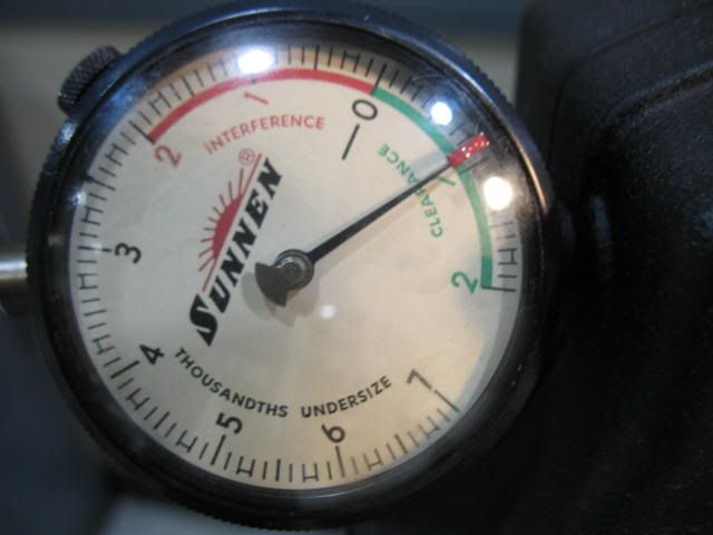
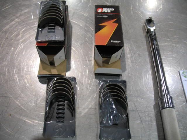
After the balance work it was time to start fitting the bearings and calculating the oil clearances.
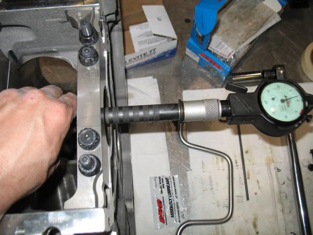
This is always fun, especially on these LS engines with ARP studs. Install the bearings, install the ARP studs, install the caps, run the fasteners down, torque them down, measure, undo the fastners, unthread the studs, pull the caps......and if the numbers weren't what you wanted - DO IT ALL OVER AGAIN! It can take the better part of an afternoon, especially if you are shooting for a 'number'. In this case on the mains, my number was .002"-.0022". GM's spec is quite a bit tighter, .0009" to .0015" nominally, to I think a service limit of about .003". With a HV oil pump, or even without, the looser number is fine and SAFE. For the rods, I like .0025"-.0027", same as a steel rod race SBC.
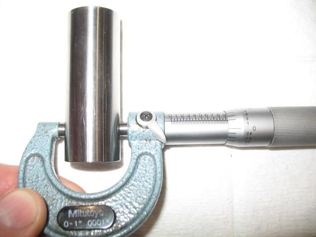
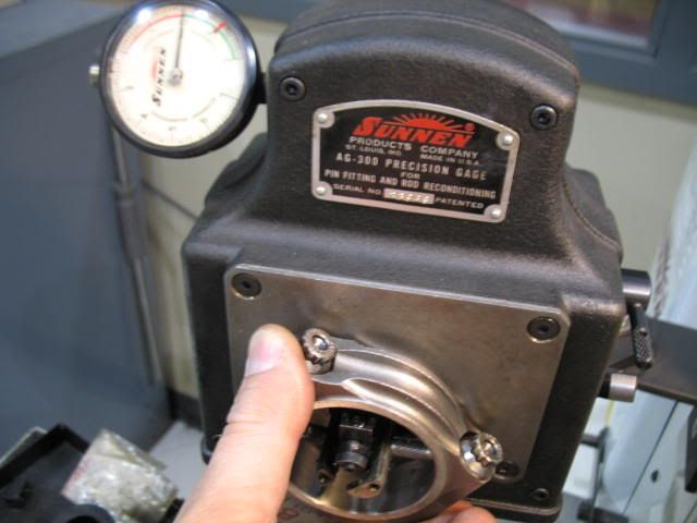
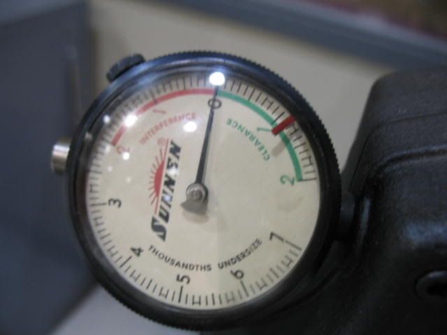
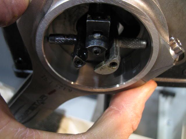
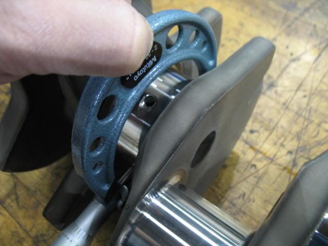
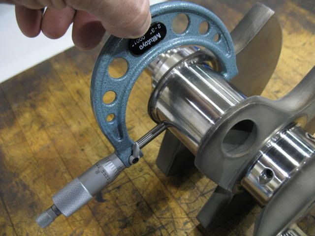
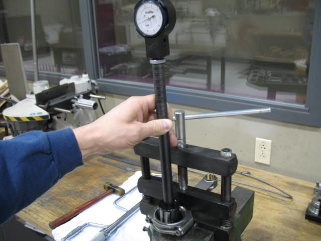
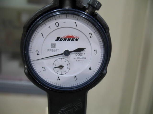
I started by getting a pin dimension from the crank for both the rod and main to set up the dial bore gauge up on. The Callies Compstar crank was round and nicely ground, maybe only a tenth of taper from what I could see.
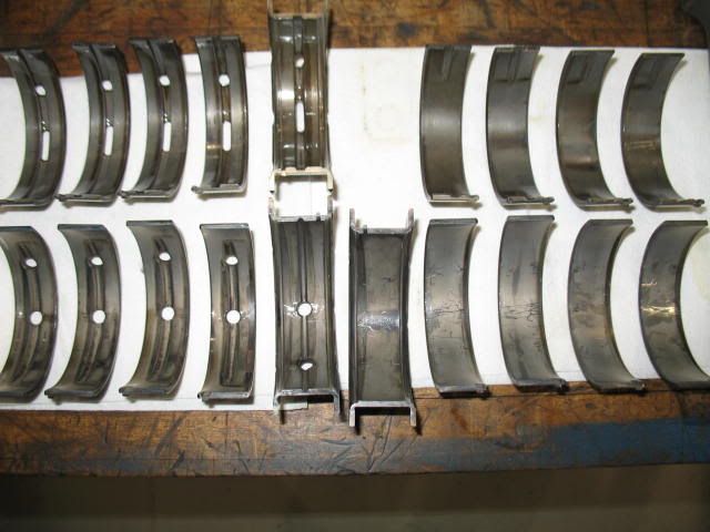
After torquing up the mains and installing 3 different sets of main bearings I got what I wanted. I ended up with a Federal Mogul 152M std. on the top and 152M1 on the bottom (cap side) for an oil clearance of .0021"-.0022". So this used up 2 sets of bearings. At a 100.00 a crack that wasn't cheap. But the 152M were running about .0026" and the 152M1's were running about .0017", with a .0015" thrust bearing oil clearance. Probably would have worked fine on this deal, but this is one of those areas that I do what has worked in the past, at least for me. Seems to me the Federal Mogul bearings always run looser than the Clevites.

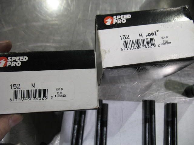
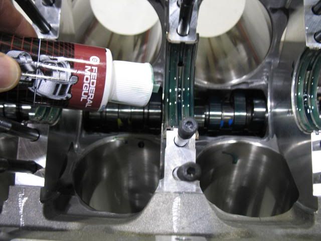
I like the Federal Moguls better anyway because they have a 3/4 groove in the bearing for more oiling to the mains. (see pics, FM are on top, Clevites on the bottom)
On the rods, a 8-7100CH std. and a 8-7100CH1 (.001" over) Federal Mogul bearing set worked out to get me .0024"-.0026" for oil clearance there. Although still 2 bearing sets needed. It is just how it worked out on this one.

Getting close to having a shortblock here fellas...
This is always fun, especially on these LS engines with ARP studs. Install the bearings, install the ARP studs, install the caps, run the fasteners down, torque them down, measure, undo the fastners, unthread the studs, pull the caps......and if the numbers weren't what you wanted - DO IT ALL OVER AGAIN! It can take the better part of an afternoon, especially if you are shooting for a 'number'. In this case on the mains, my number was .002"-.0022". GM's spec is quite a bit tighter, .0009" to .0015" nominally, to I think a service limit of about .003". With a HV oil pump, or even without, the looser number is fine and SAFE. For the rods, I like .0025"-.0027", same as a steel rod race SBC.
I started by getting a pin dimension from the crank for both the rod and main to set up the dial bore gauge up on. The Callies Compstar crank was round and nicely ground, maybe only a tenth of taper from what I could see.
After torquing up the mains and installing 3 different sets of main bearings I got what I wanted. I ended up with a Federal Mogul 152M std. on the top and 152M1 on the bottom (cap side) for an oil clearance of .0021"-.0022". So this used up 2 sets of bearings. At a 100.00 a crack that wasn't cheap. But the 152M were running about .0026" and the 152M1's were running about .0017", with a .0015" thrust bearing oil clearance. Probably would have worked fine on this deal, but this is one of those areas that I do what has worked in the past, at least for me. Seems to me the Federal Mogul bearings always run looser than the Clevites.
I like the Federal Moguls better anyway because they have a 3/4 groove in the bearing for more oiling to the mains. (see pics, FM are on top, Clevites on the bottom)
On the rods, a 8-7100CH std. and a 8-7100CH1 (.001" over) Federal Mogul bearing set worked out to get me .0024"-.0026" for oil clearance there. Although still 2 bearing sets needed. It is just how it worked out on this one.
Getting close to having a shortblock here fellas...
01-22-2010, 10:57 PM
#59
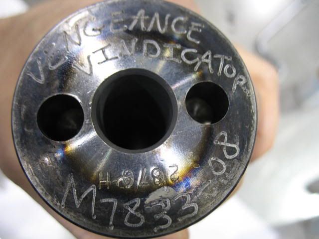
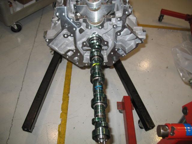
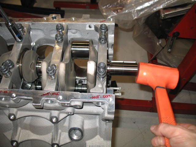
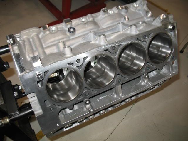
After all the prep work I started the assembly this week. First off was the install of the Vindicator camshaft. I will be degreeing it later. I like to install the camshaft first just in case there are any fitment issues.
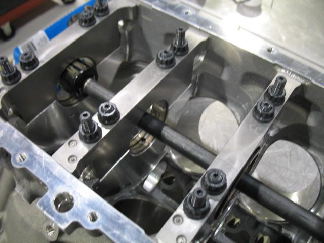
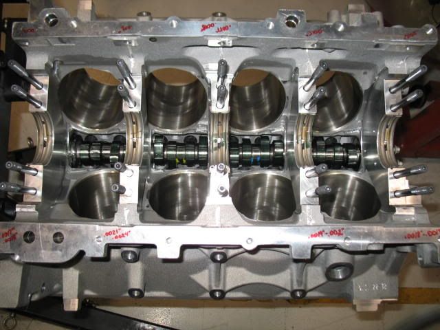
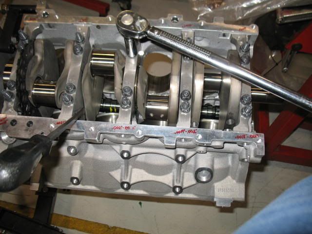
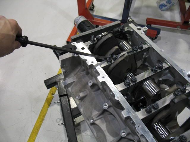
Next I installed the ARP main studs for the final time, the upper main bearings and the crankshaft then followed with the main caps. I am using Sealed Power 55-400 assembly lube. It is very high in ZDDP and slicker than snot.
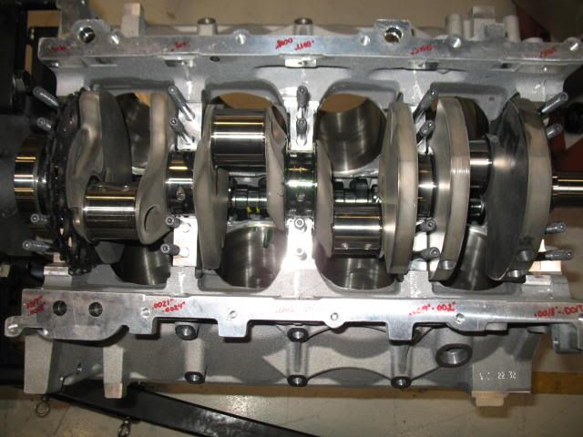
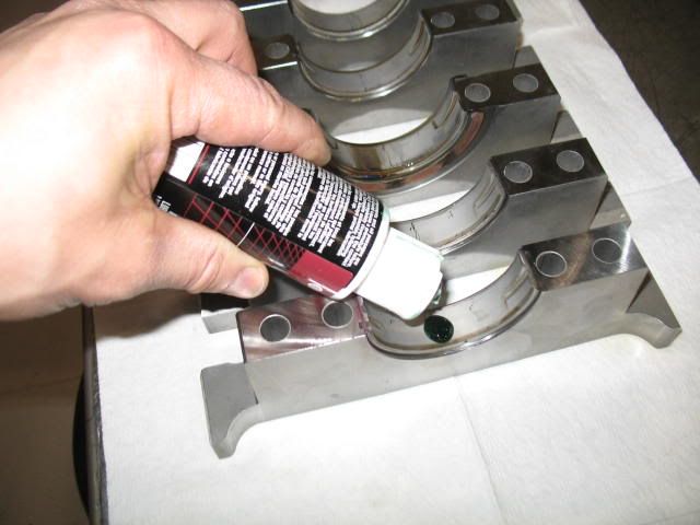
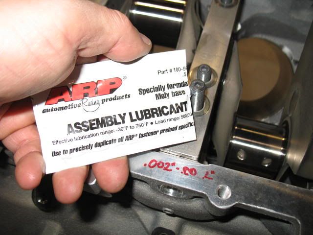
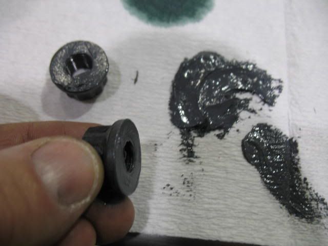
I generously lubed up the ARP main studs and nuts with their moly paste
Then before torquing all the main caps down I aligned the thrust bearing surfaces to ensure they were not overlapping.
Next I installed the ARP main studs for the final time, the upper main bearings and the crankshaft then followed with the main caps. I am using Sealed Power 55-400 assembly lube. It is very high in ZDDP and slicker than snot.
I generously lubed up the ARP main studs and nuts with their moly paste
Then before torquing all the main caps down I aligned the thrust bearing surfaces to ensure they were not overlapping.
01-22-2010, 11:08 PM
#60
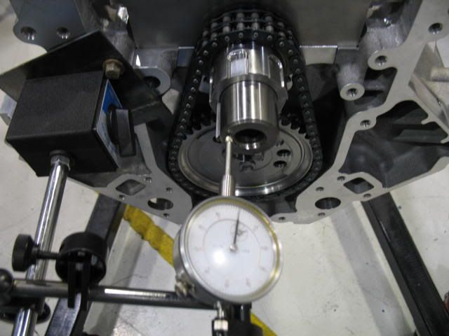
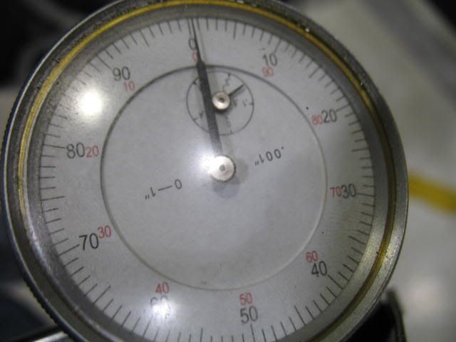
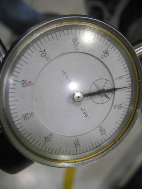
Once the crankshaft was in I torqued the mains to 55 ft lbs on the outers and 60 ft lbs on the inners and was then able to check the end play in the crank. I ended up with about .0035" - .004"
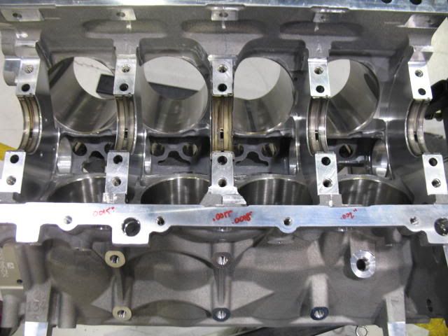
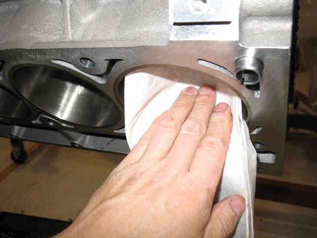
Next I wiped the cylinders out one final time. I use a white lint free towel. This lets me know how clean I got them during washing. After wiping if the towel doesn't look like it did before it entered the cylinder there is more cleaning to do. A critical step.
Then after the last wipe, a light coat of motor oil and the block is ready for the pistons and rods.
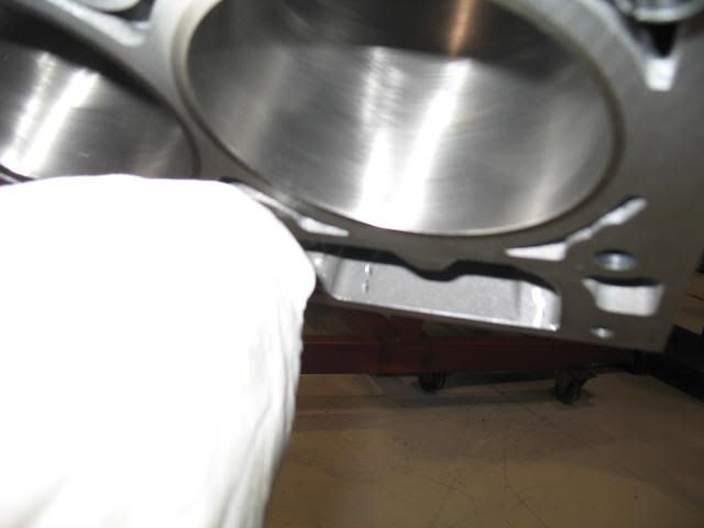