NA 'street' LS2 403 build - "From Crate to Dyno"


 01-24-2010, 10:03 PM
#85
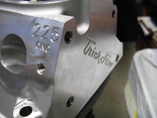
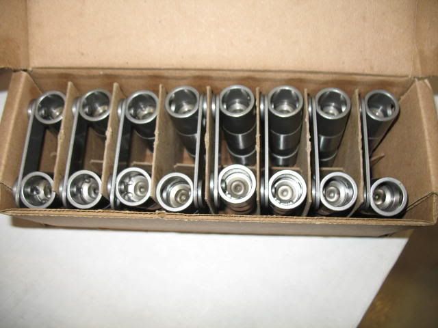
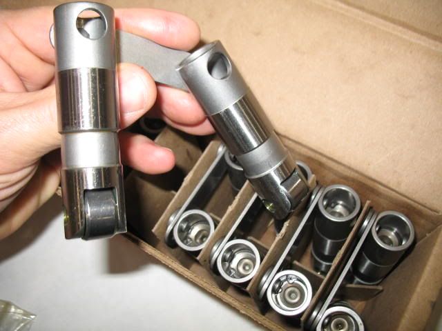
Hauled in some more parts today to work. My TFS 225's showed up on Friday from ATech. They look good for an out of the box head, I will check them more thoroughly a bit later in the week. I also got the Morel lifters this week. 
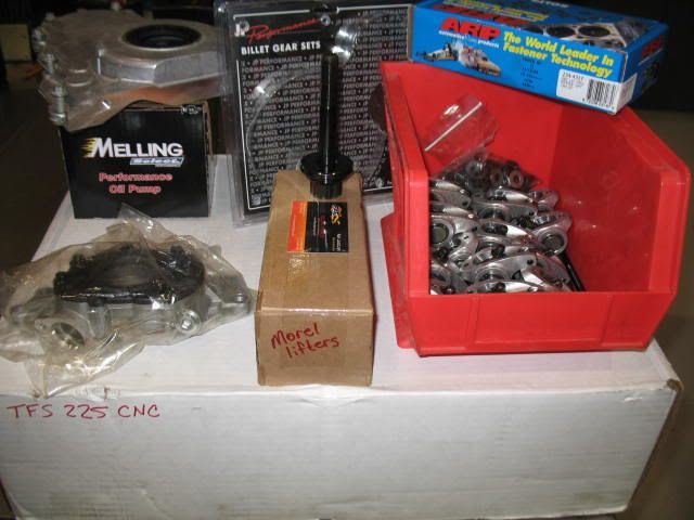
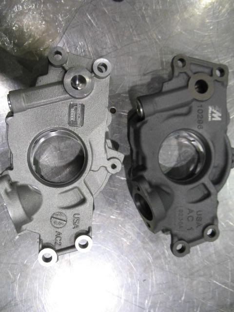
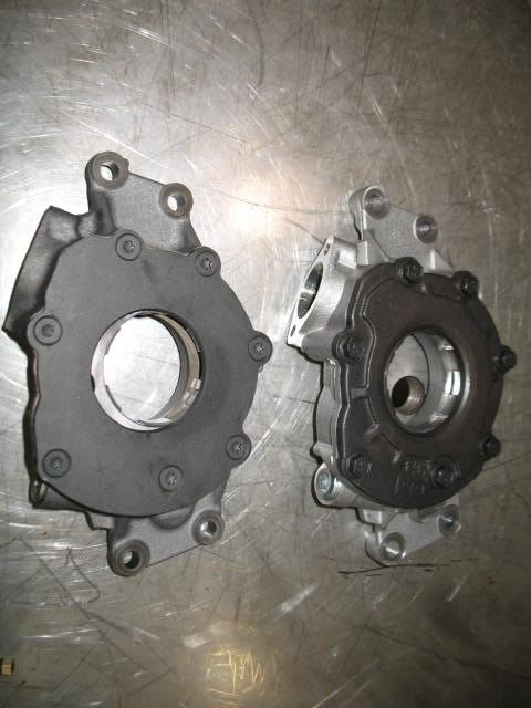
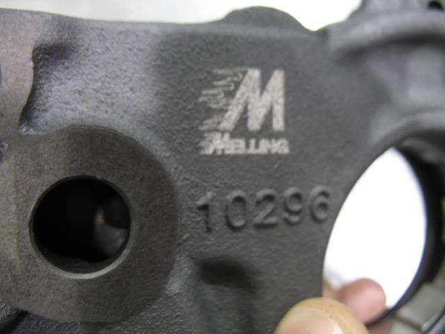
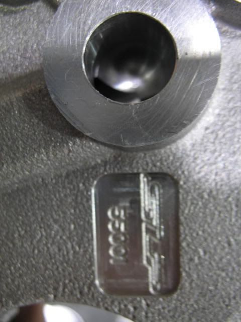
While there today I got a few small things done. I was able to compare a couple of popular oil pumps, the SLP 55001 and the Melling 10296, which is a HV. The SLP 55001 was from my original LS1 and has only a couple thousand miles on it, I was debating using it, but decided to go with the Mellings 10296 HV. Not sure what spring I will choose yet. I will say the fit of the 55001 was cake compared to the Mellings HV, it took a little work to get it to fit, but it wasn't that bad.
Both pumps inlets could use some porting.
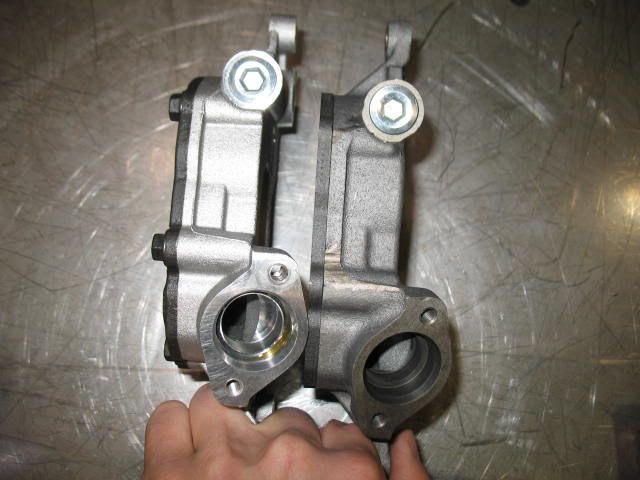
I do like the fact that the SLP 55001 doesn't require the use of the spacers, the casting was made thicker where it mounts to the block to give the clearance for the double roller chain. BTW, I am using the JP billet set (N'motion). This is a quality timing set. Torrington bearing and all.
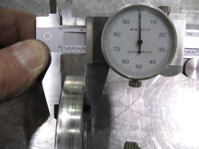
The Mellings pump uses a wider gerotor, by about .080" - .420" wide for the SLP (std. volume) and .500" wide for the Melling HV gerotor. They pick up the necessary added thickness reduction that is required to clear the cover by using countersunk fasteners on the pump cover. Notice the overall thickness measurements between the two.
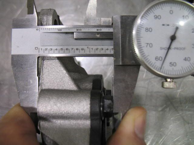
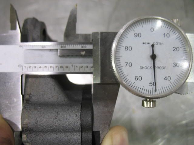
SLP 55001 Gerotor thickness
Mellings HV gerotor out of pump (for porting purposes) and measured
While there today I got a few small things done. I was able to compare a couple of popular oil pumps, the SLP 55001 and the Melling 10296, which is a HV. The SLP 55001 was from my original LS1 and has only a couple thousand miles on it, I was debating using it, but decided to go with the Mellings 10296 HV. Not sure what spring I will choose yet. I will say the fit of the 55001 was cake compared to the Mellings HV, it took a little work to get it to fit, but it wasn't that bad.
Both pumps inlets could use some porting.
I do like the fact that the SLP 55001 doesn't require the use of the spacers, the casting was made thicker where it mounts to the block to give the clearance for the double roller chain. BTW, I am using the JP billet set (N'motion). This is a quality timing set. Torrington bearing and all.
The Mellings pump uses a wider gerotor, by about .080" - .420" wide for the SLP (std. volume) and .500" wide for the Melling HV gerotor. They pick up the necessary added thickness reduction that is required to clear the cover by using countersunk fasteners on the pump cover. Notice the overall thickness measurements between the two.
SLP 55001 Gerotor thickness
Mellings HV gerotor out of pump (for porting purposes) and measured
01-24-2010, 10:35 PM
#86
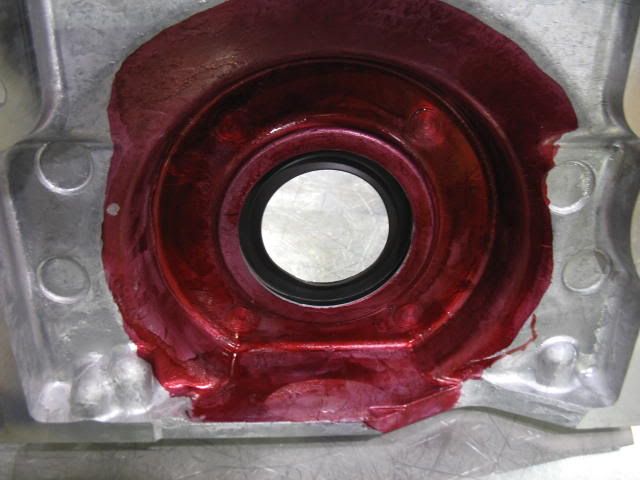
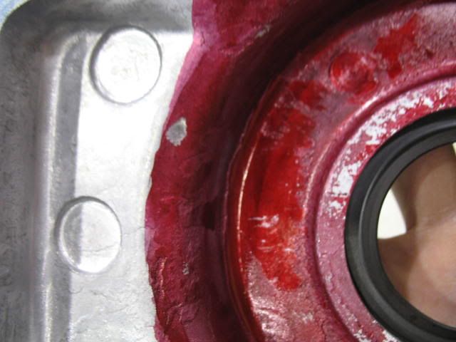
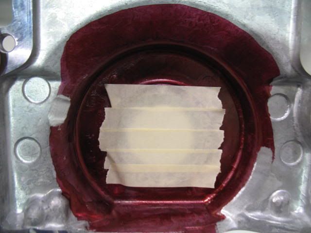
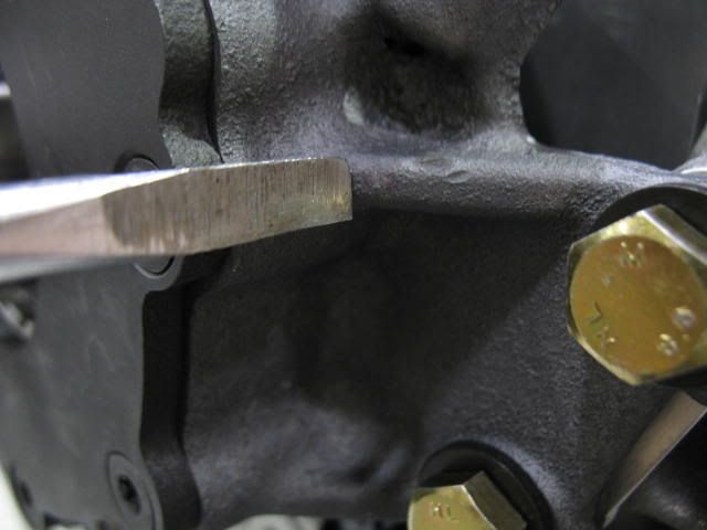
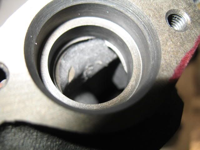
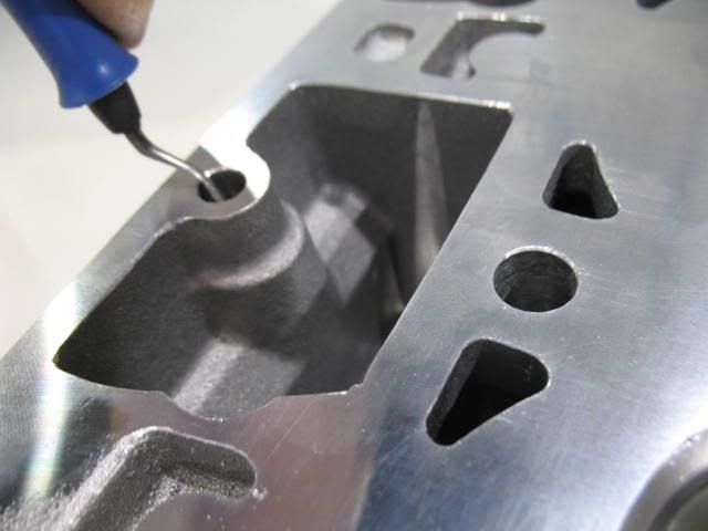
Here is what the necessary clearancing for the Mellings 10296 pump looks like for the LS2 front cover. It takes a little bit of massaging with a cartridge roll, but nothing too serious. I just installed the pump, using the spacers to the block, and then tried to fit the cover without a gasket. This way when you get it fitting with no gasket you know you will have about .060" clearance when you install the gasket in between the block and the front cover. At first it rocked a bit back and forth on the oil pump.
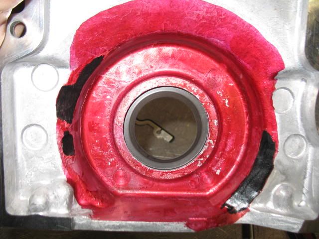
I used a little Red Dykem to paint the inside of the cover where the oil pump would go and then put the cover in place applying pressure on it and worked it a little back and forth to get whatever was hitting to rub off the machinists dye so I knew where to clearance.
Then I went and did a little massaging and tried it again and massaged some more and tried again, repainted it and tried it again, then more massaging, and again and once again until it fit. Each time a clearanced one spot it hit in another until it finally cleared. The LS2 cover is pretty thin in some areas so it was better to move slow to avoid poking a hole through it.
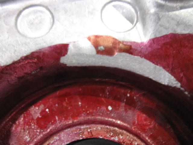
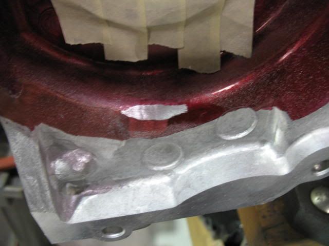
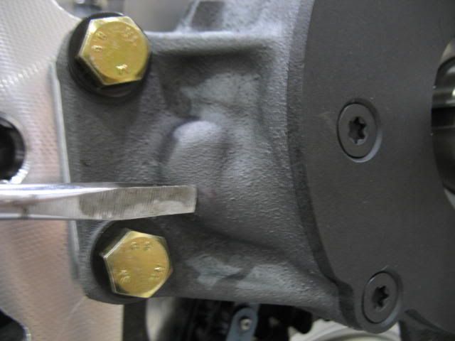
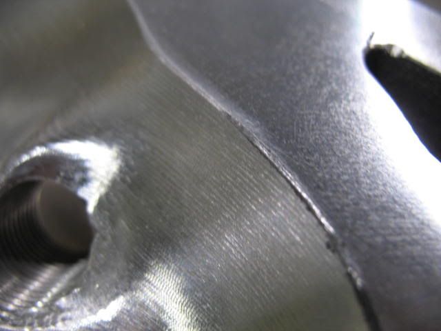
Here is one area on the oil pump casting where it hit.
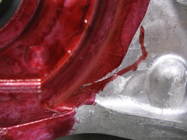
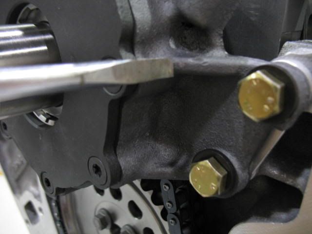
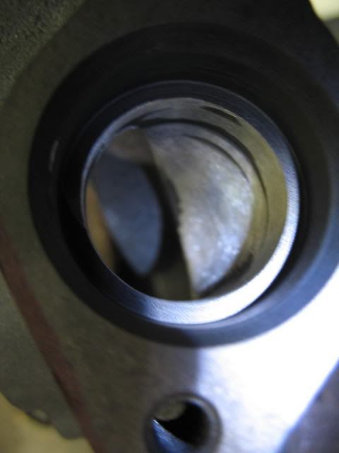
And here is one area it was hitting on the other side.
In the end, all the areas in black are where I did a little massaging. I think a button head bolt, or even removing the washers from underneath the bolt heads on the pump and using a flange headed bolt would have saved much of this time and effort. I think by doing that it may even have been a 'bolt on' deal. I didn't have any metric button heads at the shop. Maybe next time with better planning.
I used a little Red Dykem to paint the inside of the cover where the oil pump would go and then put the cover in place applying pressure on it and worked it a little back and forth to get whatever was hitting to rub off the machinists dye so I knew where to clearance.
Then I went and did a little massaging and tried it again and massaged some more and tried again, repainted it and tried it again, then more massaging, and again and once again until it fit.
Each time a clearanced one spot it hit in another until it finally cleared. The LS2 cover is pretty thin in some areas so it was better to move slow to avoid poking a hole through it.Here is one area on the oil pump casting where it hit.
And here is one area it was hitting on the other side.
In the end, all the areas in black are where I did a little massaging. I think a button head bolt, or even removing the washers from underneath the bolt heads on the pump and using a flange headed bolt would have saved much of this time and effort. I think by doing that it may even have been a 'bolt on' deal. I didn't have any metric button heads at the shop. Maybe next time with better planning.
Last edited by helicoil; 01-25-2010 at 12:14 PM. Reason: grammar - it was late!
01-25-2010, 04:05 PM
#89
TECH Resident
 01-31-2010, 01:54 PM
#91
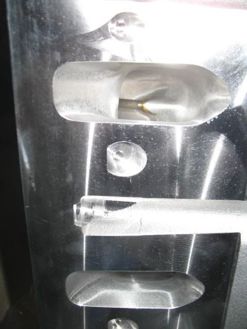
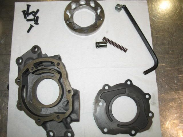
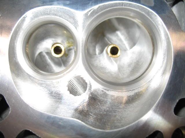
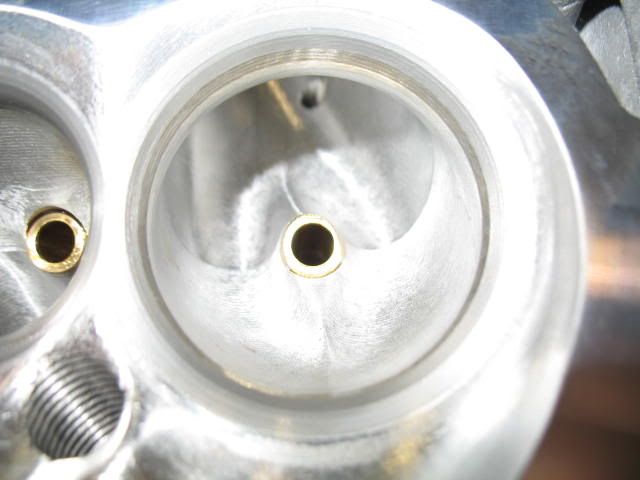
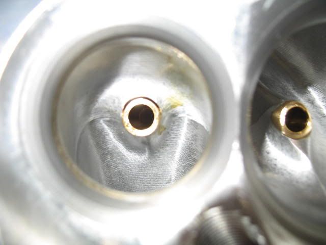
After getting the cover to fit properly I took apart the oil pump to port the entrance, there are some pretty good casting/machining lips in there that could use removal.
SLP oil pump
Melling 10296
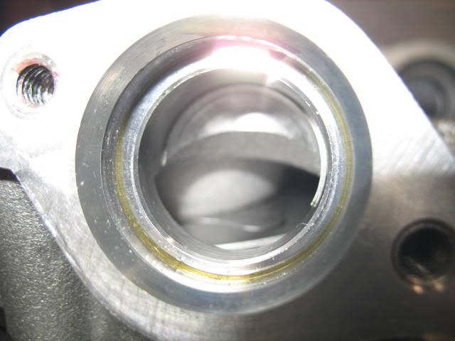
Ported Melling 1
Ported Melling 2
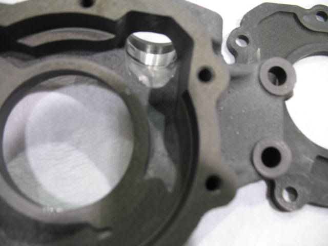
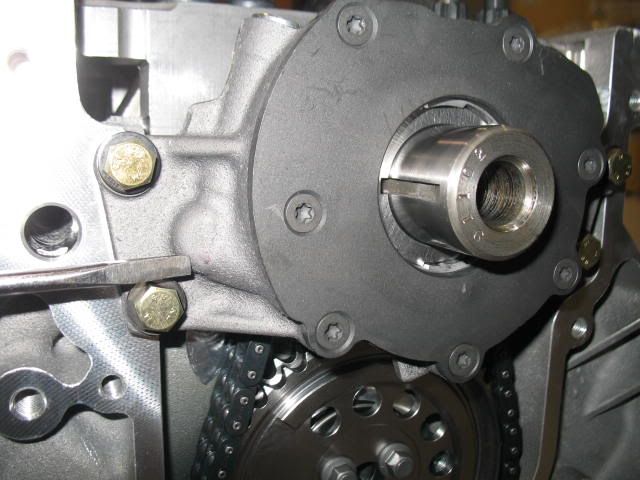
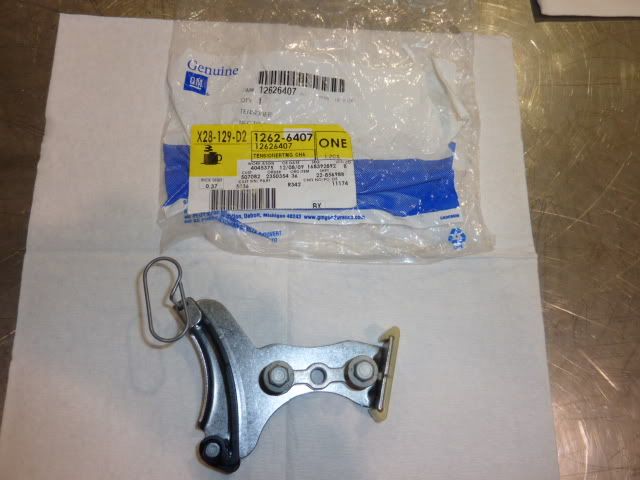
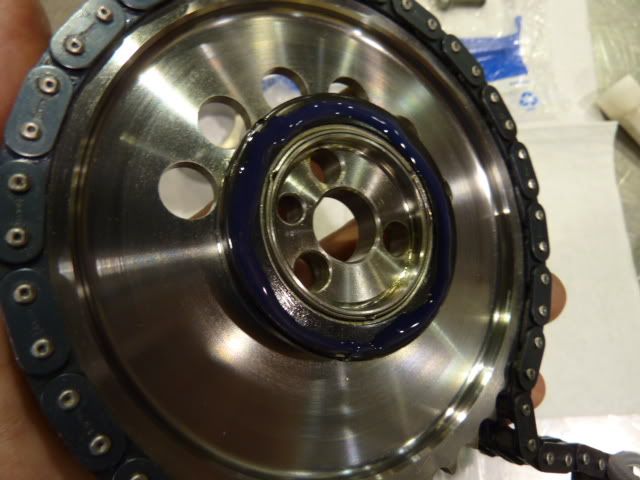
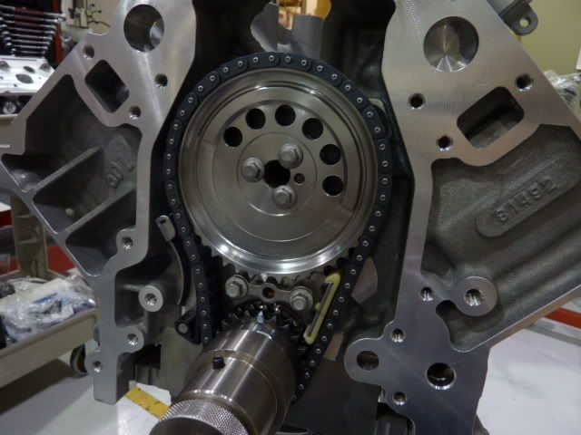
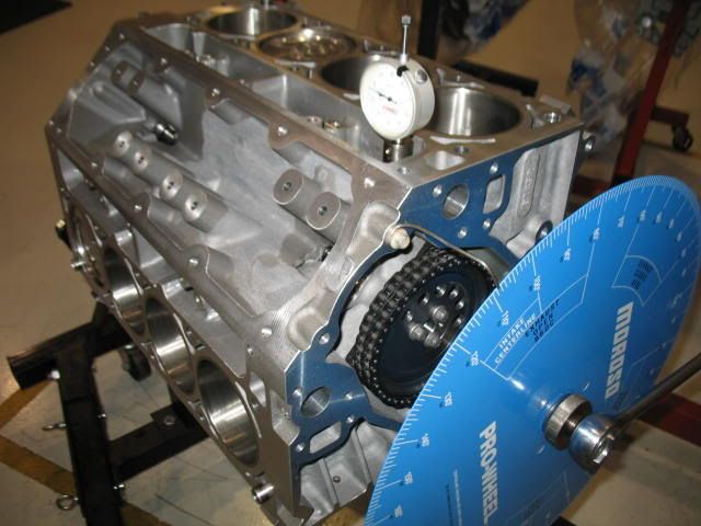
I am also going to be using the GM spring loaded timing chain damper on this engine. So in preparation for the final cam install and degreeing effort I loctited the bolts for the front oil galley cover and installed it and followed with damper and the timing gears.
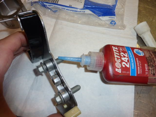
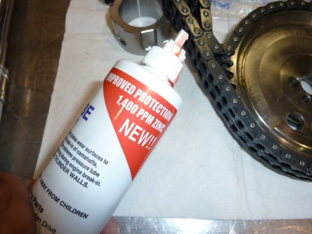
Black side of the torrington bearing to the camshaft, generously lubed with Mellings engine assembly lubricant (high in Zinc and Phosphorous) along with the tensioner guides and chain links.
SLP oil pump
Melling 10296
Ported Melling 1
Ported Melling 2
I am also going to be using the GM spring loaded timing chain damper on this engine. So in preparation for the final cam install and degreeing effort I loctited the bolts for the front oil galley cover and installed it and followed with damper and the timing gears.
Black side of the torrington bearing to the camshaft, generously lubed with Mellings engine assembly lubricant (high in Zinc and Phosphorous) along with the tensioner guides and chain links.
Last edited by helicoil; 01-31-2010 at 09:07 PM. Reason: picture change
01-31-2010, 03:04 PM
#92
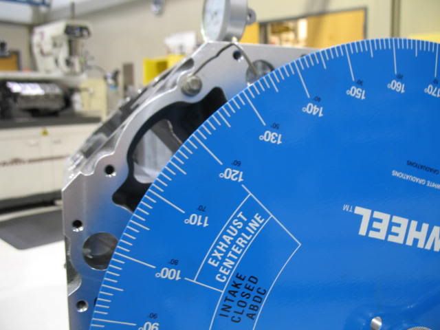
While degreeing the cam I started with the lower gear in advanced 2 degrees and then degreed the cam to see where it was at, I generally like to run most cams here to compensate for chain slack/stretch in a running engine but you always need to check your valve events against a degree wheel to be sure you got what you are supposed to have. I knowingly bought a used custom camshaft where I did not expect to get a cam card so I am speculating a few things here but have a pretty good idea where I want it to be.
So at first check I find the ICL to be 106 (cam in 2 degrees advanced), the camshaft is supposed to have a LSA of 112. So, it is obvious that there is '4 degrees' of advance ground into it, not uncommon.
The Vindicator camshaft I am using is 'supposed' to be a 240/244 duration @ .050" lift, but from what I got through measuring the valve events with the wheel installed is that it is a 242/246 @ .050". So just a tad bigger. I don't find this uncommon when checking shelf grind camshafts, but you never know until you check.
At .050" on the intake I got these numbers off the camshaft for valve events with it in at +2* advanced (106 ICL).
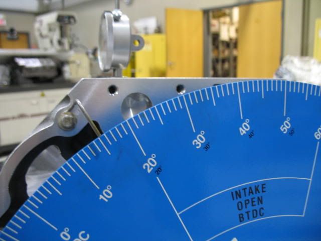
Int Opens - 15* BTDC
Int Closes - 47* ABDC
So using the appropriate math for finding intake duration via valve events.
Intake duration = Intake Open Deg BTDC+180*+Intake Close Deg ABDC
I got 15*+180+47*=242* of intake duration
Intake centerline check.
Intake duration/2 - (Intake Open BTDC)
242*/2 = 121* - 15* = 106ICL
Here is what it comes out to be.
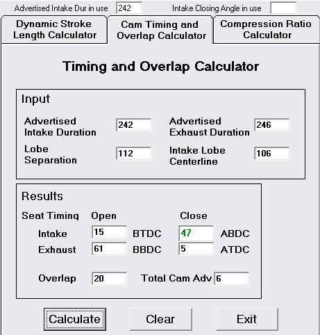
At .050" on the exhaust I got these numbers off the camshaft for valve events with it in 2* advanced (106 ICL).
Exhaust Opens - 61* BBDC
Exhaust Closes - 5* ATDC
Using this formula.
Exhaust Duration = Exhaust Open Deg BBDC+180+Exhaust Close Deg ATDC
I got.
61*+180+5*=246*
Exhaust centerline check.
Exhaust duration/2 - (Exhaust Close ATDC)
246*/2= 123* - 5* = 118 ECL
So to solve for the Lobe Separation Angle (LSA) I used this math.
LSA = Exh centerline *BTDC+Intake Centerline *ATDC / 2
118*(ECL) + 106* (ICL) = 224* /2 = 112* LSA.
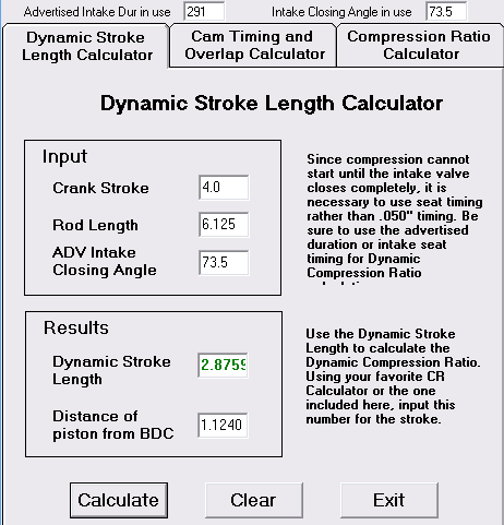
So with all this, at least I know what I got, I can go further, but this is plenty of info to satisfy what I need to know for this build. I went ahead and put it in 'straight up', "0" on the lower crank gear checked it again and it was in at a 108 ICL and I will end up with this DCR, if that means anything.
So at first check I find the ICL to be 106 (cam in 2 degrees advanced), the camshaft is supposed to have a LSA of 112. So, it is obvious that there is '4 degrees' of advance ground into it, not uncommon.
The Vindicator camshaft I am using is 'supposed' to be a 240/244 duration @ .050" lift, but from what I got through measuring the valve events with the wheel installed is that it is a 242/246 @ .050". So just a tad bigger. I don't find this uncommon when checking shelf grind camshafts, but you never know until you check.
At .050" on the intake I got these numbers off the camshaft for valve events with it in at +2* advanced (106 ICL).
Int Opens - 15* BTDC
Int Closes - 47* ABDC
So using the appropriate math for finding intake duration via valve events.
Intake duration = Intake Open Deg BTDC+180*+Intake Close Deg ABDC
I got 15*+180+47*=242* of intake duration
Intake centerline check.
Intake duration/2 - (Intake Open BTDC)
242*/2 = 121* - 15* = 106ICL
Here is what it comes out to be.
At .050" on the exhaust I got these numbers off the camshaft for valve events with it in 2* advanced (106 ICL).
Exhaust Opens - 61* BBDC
Exhaust Closes - 5* ATDC
Using this formula.
Exhaust Duration = Exhaust Open Deg BBDC+180+Exhaust Close Deg ATDC
I got.
61*+180+5*=246*
Exhaust centerline check.
Exhaust duration/2 - (Exhaust Close ATDC)
246*/2= 123* - 5* = 118 ECL
So to solve for the Lobe Separation Angle (LSA) I used this math.
LSA = Exh centerline *BTDC+Intake Centerline *ATDC / 2
118*(ECL) + 106* (ICL) = 224* /2 = 112* LSA.
So with all this, at least I know what I got, I can go further, but this is plenty of info to satisfy what I need to know for this build. I went ahead and put it in 'straight up', "0" on the lower crank gear checked it again and it was in at a 108 ICL and I will end up with this DCR, if that means anything.
01-31-2010, 03:24 PM
#93
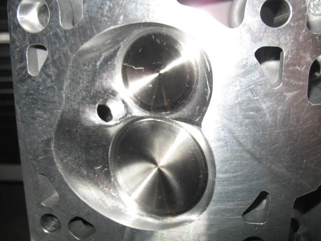
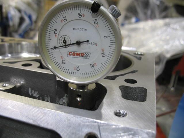
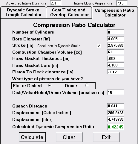
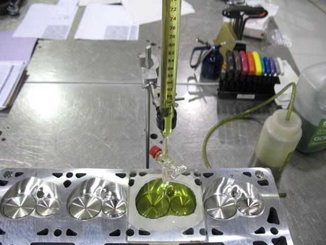
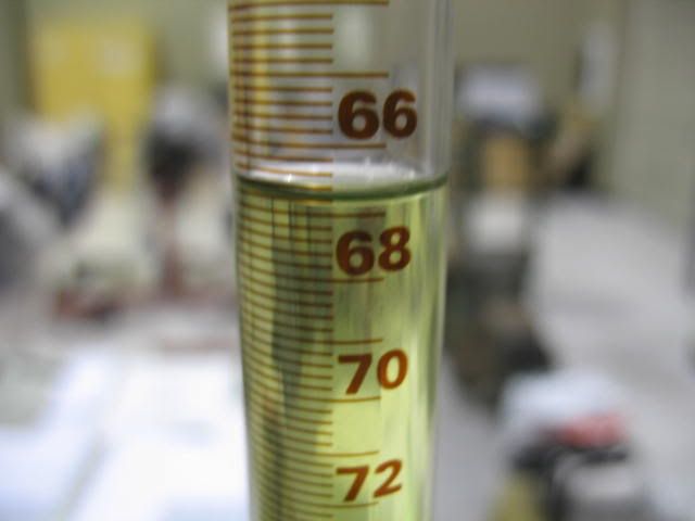
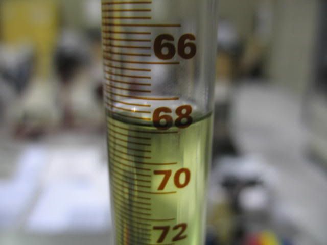
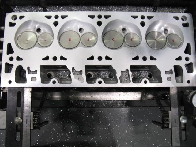
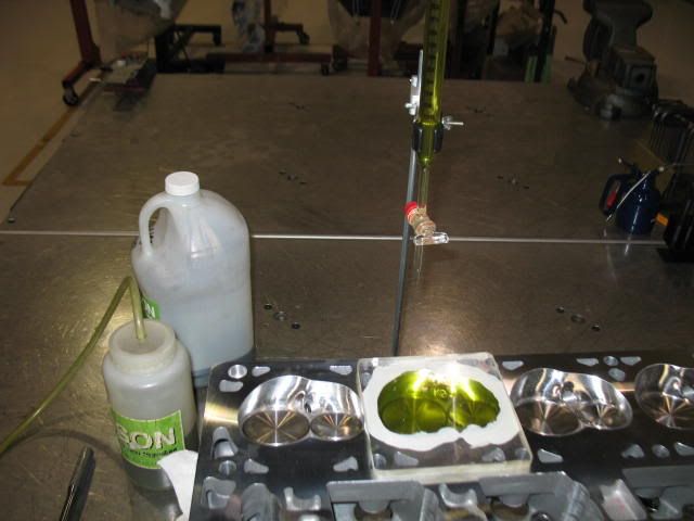
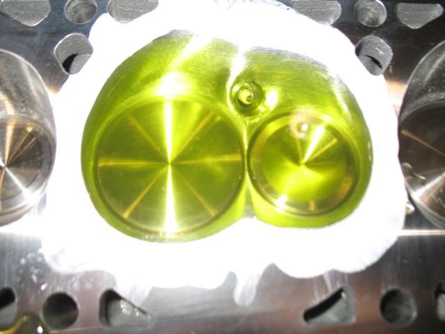
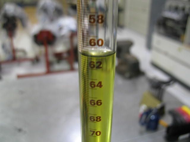
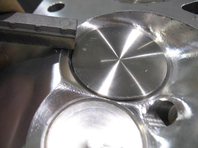
With some of the detail stuff behind me I moved on to the cylinder heads. I really want to flow them, but getting together with a friend that has a flow bench is not happening very easily - conflict of schedules. So the first thing I did was CC them. I have the CNC TFS 225's. They are supposed to be 65cc chambers. When I poured them I found between 66.8 cc and 68 cc. My target is 61 CC with the set-up I have to achieve an honest 11.3:1 compression ratio.
At .006" per cc on a flat mill, that equates to a .036" surface mill.
Here is the before measurement.
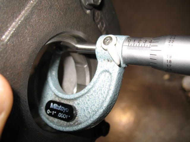
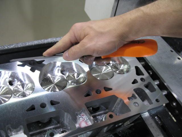
I also found a common point between both heads to measure deck thickness for a reference point. My starting reference measurement was .624" on one head and .626" on the other head.
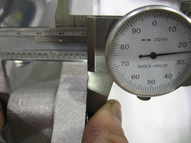
Thee target is going to be .588"-.590" thick when measured here after the milling.
At .006" per cc on a flat mill, that equates to a .036" surface mill.
Here is the before measurement.
I also found a common point between both heads to measure deck thickness for a reference point. My starting reference measurement was .624" on one head and .626" on the other head.
Thee target is going to be .588"-.590" thick when measured here after the milling.
01-31-2010, 03:50 PM
#94
I wonder how many people just assume that their heads' combustion chambers are a certain size, never measure them, bolt them on, and never know the difference (or what they might be missing)? I wouldn't have expected them to be exact, but that makes a pretty big difference if you are building the engine for a certain compression ratio.
 01-31-2010, 08:14 PM
#96
I wonder how many people just assume that their heads' combustion chambers are a certain size, never measure them, bolt them on, and never know the difference (or what they might be missing)? I wouldn't have expected them to be exact, but that makes a pretty big difference if you are building the engine for a certain compression ratio.
Usually there are more parts that come out of the box that need a little massaging than parts that come out of the box ready to be installed during an engine build.
01-31-2010, 08:44 PM
#97
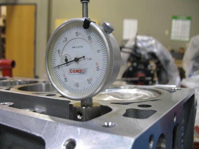
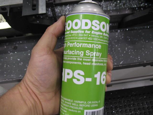
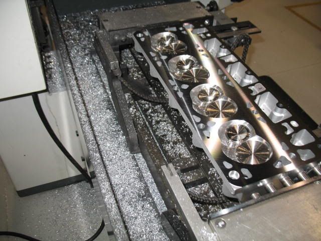
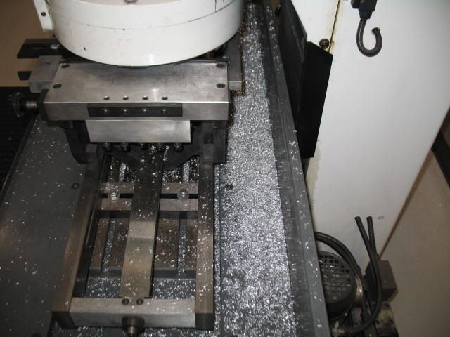
Got the heads milled this afternoon. I did about 9 cuts on each head to get them down were they needed to be. I used a rotary broach with a PCD (poly crystalline diamond) tool bit. After setting the head up parallel to the table/cutting head I began the milling process. In a machine like this, the slower the feed, the smoother the final surface, so no point in rushing. All in all, between machining, cc'ing, de-burring and washing I had about 3hrs. in this
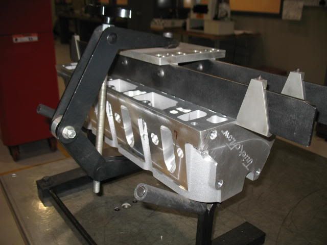
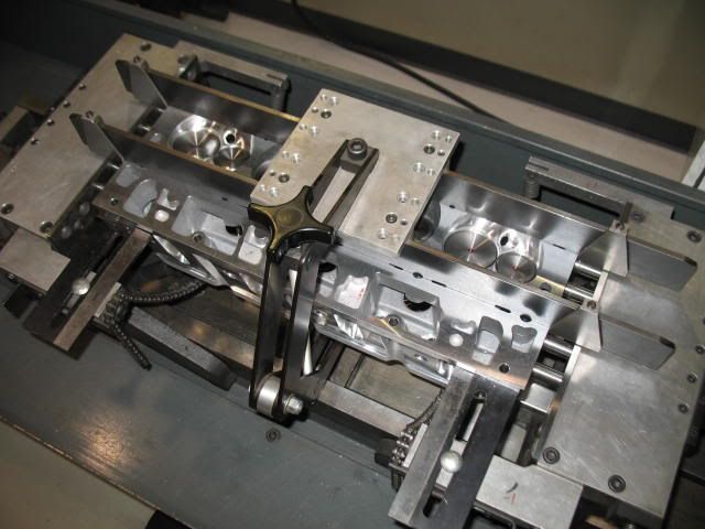
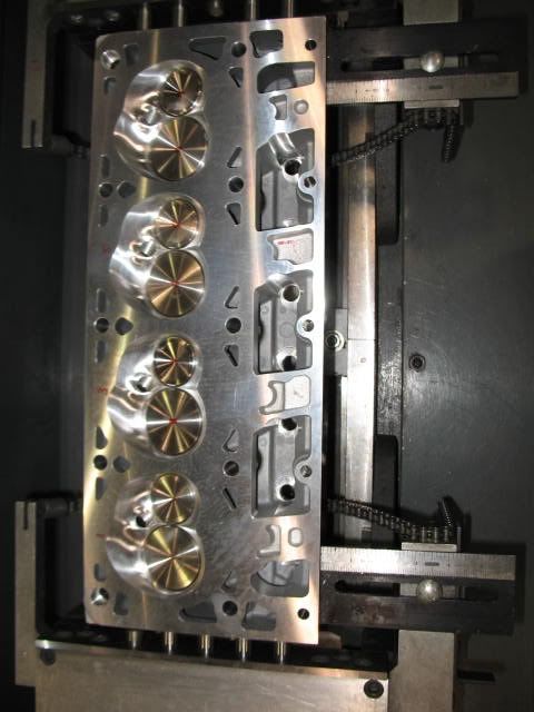
Quality aluminum like that used in the Trick Flow castings (A356-T61) machines and looks so nice when using Diamond tooling.
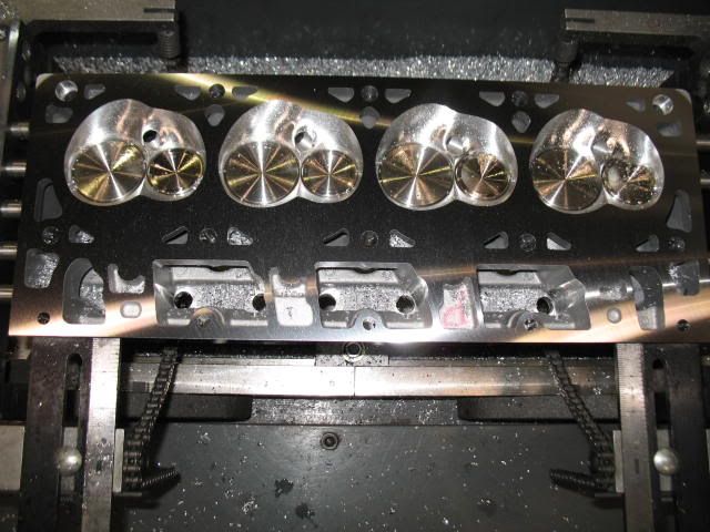
The other thing about machining aluminum is that it tends to come off in bigger pieces opposed to the little ships from machining cast iron. Look at the pile of aluminum from surfacing these two heads.
The .006" per CC rule of thumb is spot on these heads. I ended up with a head thickness of .589" on both heads from my reference point and they measured right on 61cc when I poured them again.
After surface milling anything it is always necessary to clean up the bolt holes, coolant passages and any sharp edges left behind, including the combustion chambers. I use an old honing stone, de-burring tool and a fine file to do this, it just adds to the overall finish appearance, not to mention keeps any hot corners from lighting up in the combustion chamber.
Quality aluminum like that used in the Trick Flow castings (A356-T61) machines and looks so nice when using Diamond tooling.
The other thing about machining aluminum is that it tends to come off in bigger pieces opposed to the little ships from machining cast iron. Look at the pile of aluminum from surfacing these two heads.
The .006" per CC rule of thumb is spot on these heads. I ended up with a head thickness of .589" on both heads from my reference point and they measured right on 61cc when I poured them again.
After surface milling anything it is always necessary to clean up the bolt holes, coolant passages and any sharp edges left behind, including the combustion chambers. I use an old honing stone, de-burring tool and a fine file to do this, it just adds to the overall finish appearance, not to mention keeps any hot corners from lighting up in the combustion chamber.
01-31-2010, 09:32 PM
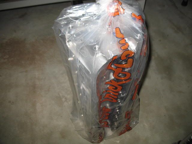
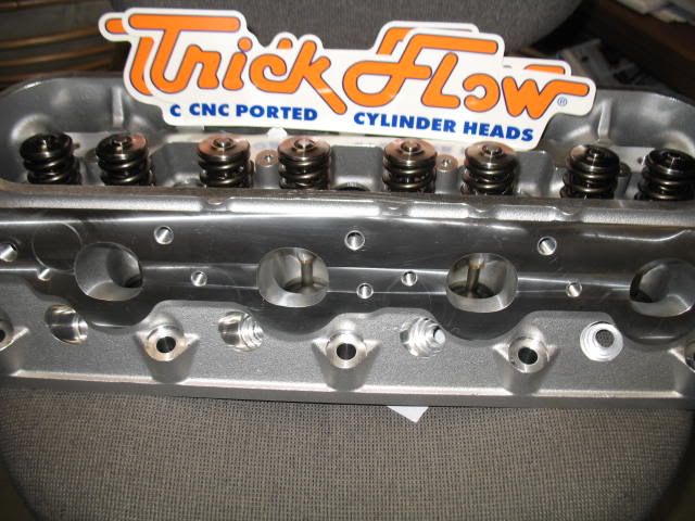
#98
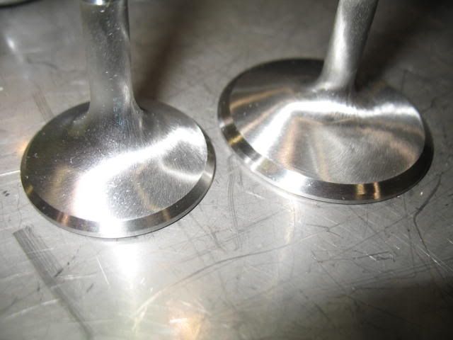
After milling the heads I cleaned them up and took a couple of beauty shots of them while apart. They really are a piece of work for out-of-the-box. We are fortunate today with the CNC 5-axis mills out there and the level of performance we all can get. I am admiring these now, because after about 1000 miles of run time, they won't look this at all. 
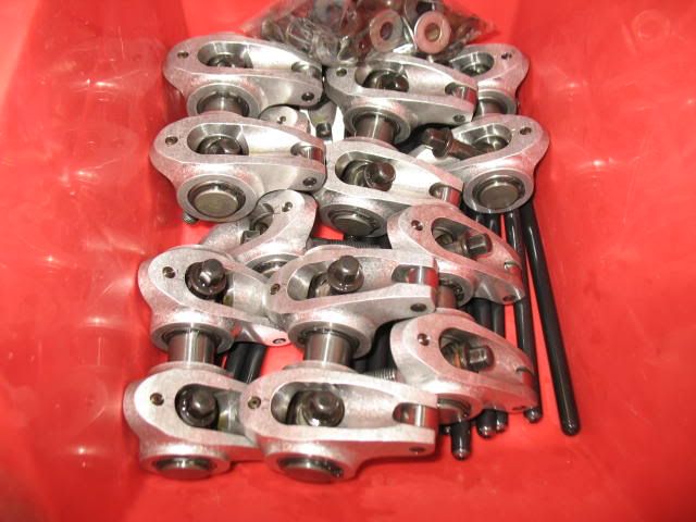
Next up is I'm going to get the heads on and set up the Yella Terra Ultra Lights for optimum valve contact and check for a pushrod length. Hopefully in the early part of this week. I also want to check the fitment of my FAST 90 manifold with the upper shell off. Always wondered after milling how that thing would fit.
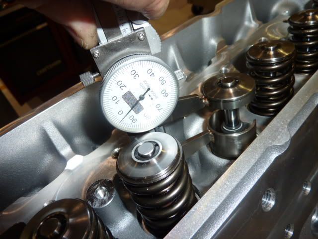
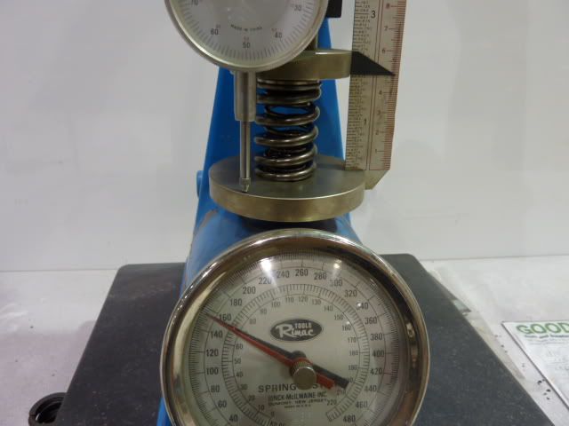
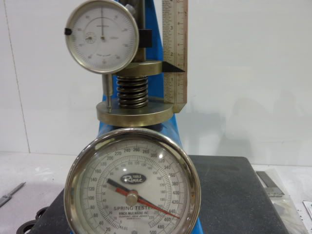
While the heads were apart I measured the installed spring heights and checked the spring pressures. Pretty much right on the button.
Installed spring heights - 1.794"- 1.803"
Seat pressure - 152-155# @ 1.800"
Open pressure - 445-450# @ compressed .600" past seat install number
Coil Bind - compressed .695" past seat install number, so they are good for a net .645" lift at the valve or so.
Next up is I'm going to get the heads on and set up the Yella Terra Ultra Lights for optimum valve contact and check for a pushrod length. Hopefully in the early part of this week. I also want to check the fitment of my FAST 90 manifold with the upper shell off. Always wondered after milling how that thing would fit.
While the heads were apart I measured the installed spring heights and checked the spring pressures. Pretty much right on the button.
Installed spring heights - 1.794"- 1.803"
Seat pressure - 152-155# @ 1.800"
Open pressure - 445-450# @ compressed .600" past seat install number
Coil Bind - compressed .695" past seat install number, so they are good for a net .645" lift at the valve or so.
01-31-2010, 09:42 PM
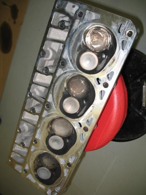
#99
Here is a set heads I just looked over with only 900 miles on them. They aren't too pretty to look at after they have been run. Makes you kind of wonder about all the polishing in the chambers, that carbon still sticks to it like stink on sh*t. They aren't easy to clean up either. These had just come out of the spray wash cabinet. They looked pretty much like the TFS's I am using last year about this time.