NA 'street' LS2 403 build - "From Crate to Dyno"


 Great thread !!!
 02-01-2010, 04:38 PM
#103
Wow man, your attention to detail is way beyond anything I've ever seen. Truly awesome, and very informative. I don't see how this engine wouldn't last quite a while. Your clearances are obviously better than production stuff (the surface of my new L92 heads look like washer-boards compared to the mirrors you milled), and while your not running a production cam and compression, its still pretty mild when compared to more dedicated race engines. Thanks for going into such detail and taking good photos.
02-01-2010, 09:36 PM
#104
Thanks guys.
Tonight I did some quick checking of a prelimenary lifter pre-load and looked at the FAST 90 intake fit.
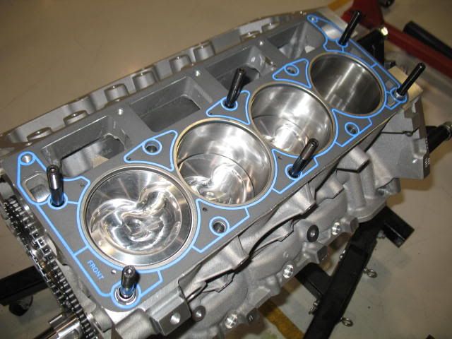
I used a pair of composite Felpro 1041's I have for mock up (no MLS coatings to contend with, plus I don't like handling the MLS head gaskets until the install time) which measure .041" compressed, so that will be .012" less than the head gasket I will be using and will need to be accounted for in my lifter pre-load measurements.
I dropped in 4 pr of the Morel lifters, one in each corner as I will check for pushrod lengths on each corner of the engine before coming up with a final measurement.
Next I dropped the heads on and used just 6 head studs per side tightened up to about 35 ft. lbs to get my pushrod length measurements, the composite bodied Felpro 1041 is quite dense and will not change thickness very much with torque, unlike the MLS stuff, so 35 ft. lbs is fine.
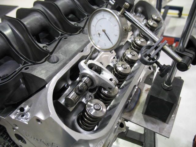
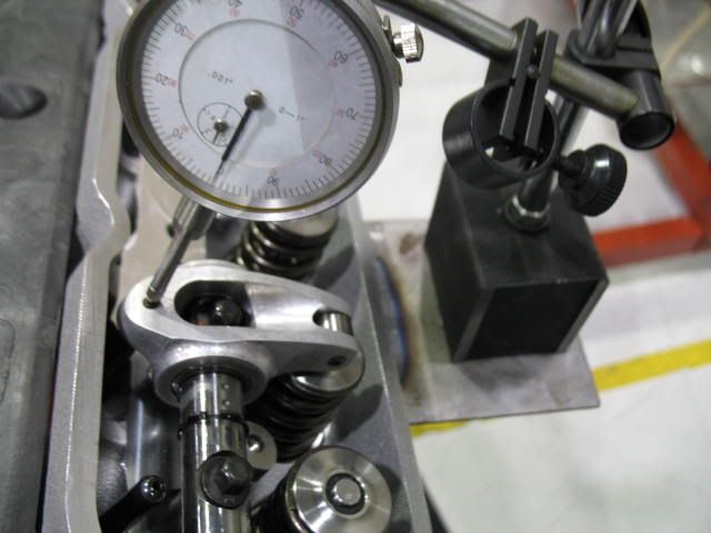
Then I bolted and indicator base to the head and set up a dial indicator.
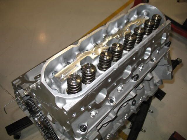
Since I am using a Yella Terra Ultra Light shaft rocker with two rockers per shaft I will take one rocker off the shaft to avoid it interfering with what I am trying to accomplish, then I will put the other rocker back on and take off the one I started with to do the same procedure on both intake and exhaust valves.
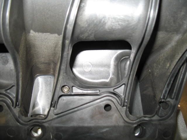
Here is what the set-up I am using for this looks like. Pretty straight forward, just using a compound indicator stand to get the dial indicator right where I want it.
I dropped in a 7.500" pushrod for starters since I had one.
I lightly tightened up both of the rocker shaft bolts to take the excess lash out of the rocker arm careful to avoid pre-loading the lifter I am working with.
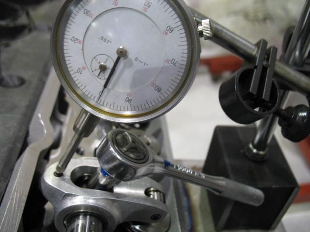
Then I rolled the engine over to get the cam on the base circle of the lobe and zeroed the indicator on the pushrod side of the rocker and made sure there was no pre-load on the lifter.
I then brought the rocker bolt down and backed it off, and then brought it down again re-zeroing the indicator. Then I started to tighten up the rocker shaft hold down bolt watching the lifter pre-load take place while measuring it with the indicator.
I found for every 1/4 turn of the rocker shaft hold down bolt that it was about .018"-.020" lifter pre-load, so a FULL turn was about .072"-.080".
Zero
1/4 turn
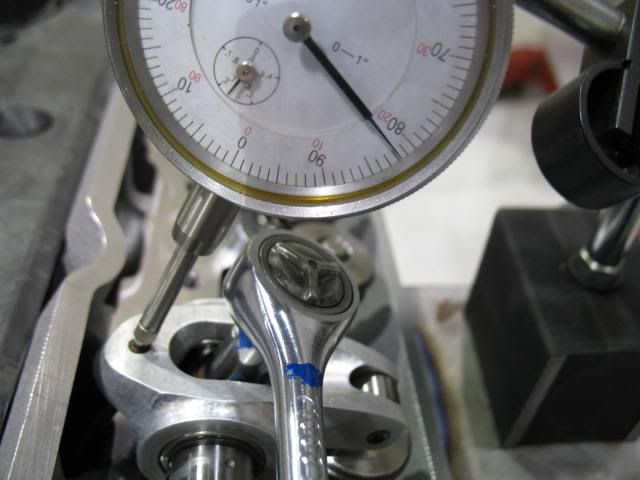
With the 7.500" pushrod and the shaft rocker bolt torqued to 22ft. lbs I got about .085" pre-load (or 1 1/8 turns), a little on the high side, but not bad.
When I add the additional .012" for the head gasket I will be running I will be in nice safe place to run the lifters at.
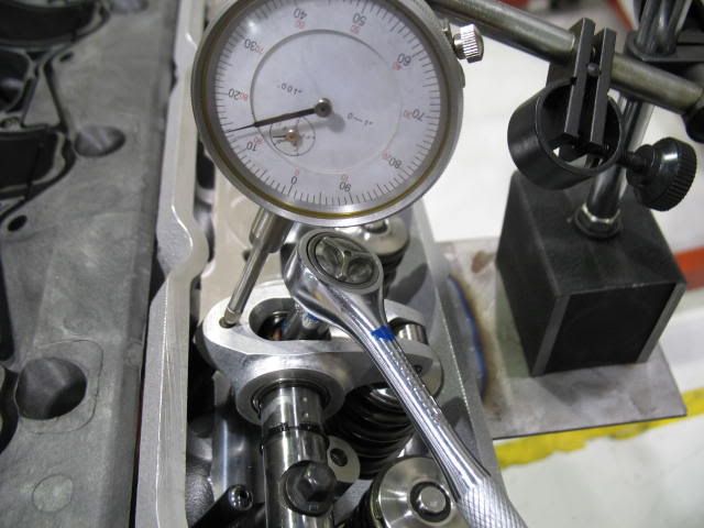
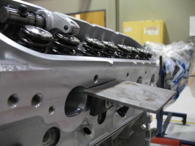
I need to finish checking the other 3 corners of the engine and then figure out what the rocker geometry/valve tip wipe looks like so I know whether or not I need to add stand thickness (additonal shims) to the Yella Terra shaft mounts. For this I will need to replace the Morel lifters with a solid 'set-up' lifter I made by taking apart the lifter and stacking small shims underneath the plunger.
Probably should have done this first as I realize now sitting here typing this up. Oh well, I was anxious to see what the FAST 90 intake fit was going to fit like. I have it apart right now because I am sanding it down and going to paint the top shell gloss black.
So here it is, I would have needed to mill another .075" - .090" off the heads to get the port floor to line up with the manifold floor Pretty typical from what I understand on these. It would have only been worse not milling the heads any. I wonder what an LS6 manifold or a NEW FAST 102 would fit like here?
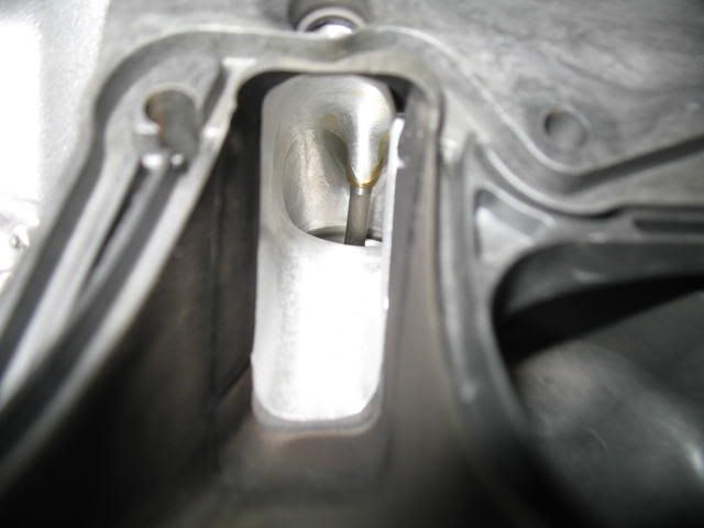
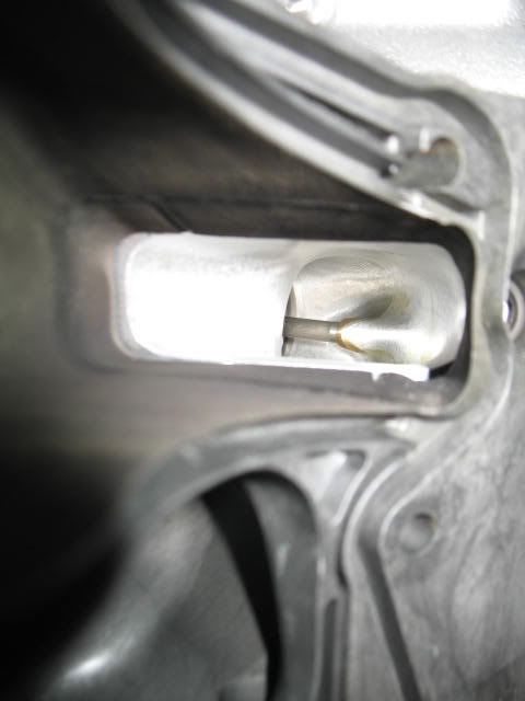
I suppose I could open the intake port, but I don't think it would be worth much here. Maybe some cylinder head guru can chime in....
Tonight I did some quick checking of a prelimenary lifter pre-load and looked at the FAST 90 intake fit.
I used a pair of composite Felpro 1041's I have for mock up (no MLS coatings to contend with, plus I don't like handling the MLS head gaskets until the install time) which measure .041" compressed, so that will be .012" less than the head gasket I will be using and will need to be accounted for in my lifter pre-load measurements.
I dropped in 4 pr of the Morel lifters, one in each corner as I will check for pushrod lengths on each corner of the engine before coming up with a final measurement.
Next I dropped the heads on and used just 6 head studs per side tightened up to about 35 ft. lbs to get my pushrod length measurements, the composite bodied Felpro 1041 is quite dense and will not change thickness very much with torque, unlike the MLS stuff, so 35 ft. lbs is fine.
Then I bolted and indicator base to the head and set up a dial indicator.
Since I am using a Yella Terra Ultra Light shaft rocker with two rockers per shaft I will take one rocker off the shaft to avoid it interfering with what I am trying to accomplish, then I will put the other rocker back on and take off the one I started with to do the same procedure on both intake and exhaust valves.
Here is what the set-up I am using for this looks like. Pretty straight forward, just using a compound indicator stand to get the dial indicator right where I want it.
I dropped in a 7.500" pushrod for starters since I had one.
I lightly tightened up both of the rocker shaft bolts to take the excess lash out of the rocker arm careful to avoid pre-loading the lifter I am working with.
Then I rolled the engine over to get the cam on the base circle of the lobe and zeroed the indicator on the pushrod side of the rocker and made sure there was no pre-load on the lifter.
I then brought the rocker bolt down and backed it off, and then brought it down again re-zeroing the indicator. Then I started to tighten up the rocker shaft hold down bolt watching the lifter pre-load take place while measuring it with the indicator.
I found for every 1/4 turn of the rocker shaft hold down bolt that it was about .018"-.020" lifter pre-load, so a FULL turn was about .072"-.080".
Zero
1/4 turn
With the 7.500" pushrod and the shaft rocker bolt torqued to 22ft. lbs I got about .085" pre-load (or 1 1/8 turns), a little on the high side, but not bad.
When I add the additional .012" for the head gasket I will be running I will be in nice safe place to run the lifters at.
I need to finish checking the other 3 corners of the engine and then figure out what the rocker geometry/valve tip wipe looks like so I know whether or not I need to add stand thickness (additonal shims) to the Yella Terra shaft mounts. For this I will need to replace the Morel lifters with a solid 'set-up' lifter I made by taking apart the lifter and stacking small shims underneath the plunger.
Probably should have done this first as I realize now sitting here typing this up.
Oh well, I was anxious to see what the FAST 90 intake fit was going to fit like. I have it apart right now because I am sanding it down and going to paint the top shell gloss black.So here it is, I would have needed to mill another .075" - .090" off the heads to get the port floor to line up with the manifold floor
Pretty typical from what I understand on these. It would have only been worse not milling the heads any. I wonder what an LS6 manifold or a NEW FAST 102 would fit like here?I suppose I could open the intake port, but I don't think it would be worth much here. Maybe some cylinder head guru can chime in....
 02-03-2010, 10:17 PM
#108
It went to a local in one of the Camaro clubs. He had it running over the Christmas holidays. In a 6-spd driveline, 12-bolt, with AFR 205's and a Vindicator (his top half) it did 517RWHP. I built it for one of my cars but chose to unload it in an effort to buy another car. That was a nice one, good price too.
02-03-2010, 11:58 PM
#109
TECH Regular
iTrader: (4)
Join Date: Sep 2008
Location: Joplin, MO
Posts: 477
Likes: 0
Received 0 Likes
on
0 Posts

If you don't mind me asking, what's the purpose of finding the lifter pre-load? Is it to find out if you're loading it too much? What's the preload supposed to be at?


 02-06-2010, 10:58 PM
#114
TECH Veteran
iTrader: (12)
Join Date: Dec 2004
Location: Rockville, MD
Posts: 4,354
Likes: 0
Received 0 Likes
on
0 Posts
<snip>
http://i160.photobucket.com/albums/t...re-Load026.jpg
I suppose I could open the intake port, but I don't think it would be worth much here. Maybe some cylinder head guru can chime in....
http://i160.photobucket.com/albums/t...re-Load026.jpg
I suppose I could open the intake port, but I don't think it would be worth much here. Maybe some cylinder head guru can chime in....
02-07-2010, 03:17 PM
#116
I am going to say not, these FAST intakes have to always fit this way. The milling I did on the heads (typical) certainly would only have helped the situation. We are only talking .036" a head, so it would have been even a bit worse if they were run out of the box.
I leaning towards not doing anything here. I would assume most don't either. As mentioned above it would require filling the manifold floor with a two part epoxy, or lowering the cylinder head intake port. Apparantly, most the airflow gains are made up top (intake roof) if you look at the worked manifolds out there.
BTW, no updates guys, too busy with work to play right now. Still looks the same as last pictured.
 02-21-2010, 06:27 PM
#120
I need to finish checking the other 3 corners of the engine and then figure out what the rocker geometry/valve tip wipe looks like so I know whether or not I need to add stand thickness (additonal shims) to the Yella Terra shaft mounts. For this I will need to replace the Morel lifters with a solid 'set-up' lifter I made by taking apart the lifter and stacking small shims underneath the plunger.
Probably should have done this first as I realize now sitting here typing this up. Oh well, I was anxious to see what the FAST 90 intake fit was going to fit like. I have it apart right now because I am sanding it down and going to paint the top shell gloss black.
So here it is, I would have needed to mill another .075" - .090" off the heads to get the port floor to line up with the manifold floor Pretty typical from what I understand on these. It would have only been worse not milling the heads any. I wonder what an LS6 manifold or a NEW FAST 102 would fit like here?
...
Probably should have done this first as I realize now sitting here typing this up.
Oh well, I was anxious to see what the FAST 90 intake fit was going to fit like. I have it apart right now because I am sanding it down and going to paint the top shell gloss black.So here it is, I would have needed to mill another .075" - .090" off the heads to get the port floor to line up with the manifold floor
Pretty typical from what I understand on these. It would have only been worse not milling the heads any. I wonder what an LS6 manifold or a NEW FAST 102 would fit like here?...
Again, nice work,
Kevin