


Details of the electronic throttle (wiring, internals)

Thread Starter
On The Tree
iTrader: (1)
Joined: Jul 2002
Posts: 192
Likes: 0
From: Austin, TEXAS > *
I'm looking for some specifics on the 90mm drive by wire throttle body.
The connector has 6 pins labeled A-F.
A, B have to be the driver input (1 ground, 1 servo pulse).
I can't tell yet for the other 4. I need a better way of clipping my meter on these leads. If no one knows, I'll grab some tiny spade connectors tomorrow and try again. C-F are all connected (1.4k-4.21k between any two pins in this group, varies by which pair of course).
Pending questions:
1) What's the polarity of the drive pins A,B
2) What's the servo pulse frequency (I can test this if I find someone with a gto or vette)
3) What exactly are the pins C-F?
Thread Starter
On The Tree
iTrader: (1)
Joined: Jul 2002
Posts: 192
Likes: 0
From: Austin, TEXAS > *
Still looking for info from an LS2 vehicle. 
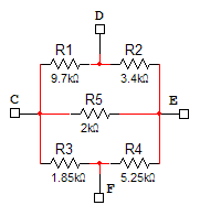
With the throttle in the closed position:
Rcd = 3.29k, falls as throttle opens
Rce = 1.41k, constant as throttle opens
Rcf = 1.47k, rises as throttle opens
Rde = 2.62k, rises as throttle opens
Rdf = 4.21k, constant as throttle opens
Ref = 2.14k, falls as throttle opens
I did note that Rcd+Rcf=Rde+Ref = 4.76k
Still unsure of how how it works out internally though.
Last edited by 280Z28; Nov 10, 2006 at 06:13 PM.
Thread Starter
On The Tree
iTrader: (1)
Joined: Jul 2002
Posts: 192
Likes: 0
From: Austin, TEXAS > *
Originally Posted by OldMonte
There are three position sensors each of which has a unique slope and voltage, its a redundancy thing
C: Position sensor 1
E: Position sensor 2
D: +5V ref
F: Gnd
Trending Topics
Thread Starter
On The Tree
iTrader: (1)
Joined: Jul 2002
Posts: 192
Likes: 0
From: Austin, TEXAS > *
Wow, post #7 in this thread:
"hrottle Actuator Control, VSS, Scan Tool Normal Ranges 1"
http://www.ls2.com/forums/showthread...hreadid=405808
"hrottle Actuator Control, VSS, Scan Tool Normal Ranges 1"
http://www.ls2.com/forums/showthread...hreadid=405808
LS1 Tech Stories
The Best V8 Stories One Small Block at Time

6 Common C5 Corvette Failures and What's Involved In Repairing Them
Pouria Savadkouei
Retro Modern Bandit Pontiac Trans AM Comes With Burt Reynolds' Autograph
Verdad Gallardo
Top 10 Greatest Cadillac V Series Performance Models Ever, Ranked
Pouria Savadkouei
Top 10 Most Powerful Chevy Trucks Ever Made!

Hennessey's New Supercharged Silverado ZR2 Has 700 HP
Verdad Gallardo
Coachbuilt N2A Anteros Is an LS2-Powered C6 Corvette In Italian Clothes
Verdad Gallardo
Awesome K5 Blazer Restomod Comes With C7 Corvette Power
Verdad Gallardo
10 Camaros You Should Never Buy

10 LS Engine Myths That Refuse to Die
Verdad Gallardo Thread Starter
On The Tree
iTrader: (1)
Joined: Jul 2002
Posts: 192
Likes: 0
From: Austin, TEXAS > *
My experimentation with the throttle brings me to a conclusion:
I'm controlling the throttle with a simple PID controller for a constant frequency square wave with varying duty cycle. My supply voltage is 5.17V with ~1V drop across my low side driver. The controller sits right around 50% duty cycle to keep the servo open to position A. A reference source (that link 1 post up) states that it should take a 14-26% duty cycle to keep it open to position A.
By my calculation, I've applied an effective (time averaged) 2V source.
2/.26 + 1 = 8.7V
2/.14 + 1 = 15.3V
Is this the correct calculation/conclusion that the servo is built to handle a 9-15V supply? It sure makes perfect sense in an automotive application...

Thread Starter
On The Tree
iTrader: (1)
Joined: Jul 2002
Posts: 192
Likes: 0
From: Austin, TEXAS > *