


LS2 Throttle Body Install
I just installed a ls2 throttle body and I cant get my car to start. I have three error codes P1516, P2101 and P2119. I had discovered that I had switched the low reference with the 5-volt reference and TP sensor 1 with TP sensor 2 but these same three error codes remain. Any help would be appreciated.
Last edited by Aaron_Provost; Feb 3, 2014 at 08:42 PM.
TECH Enthusiast
Joined: Dec 2012
Posts: 696
Likes: 0
From: WEST PALM BEACH FL
First things first! Without trying to start your car u need to clear the codes and then check and see if the blade is opening and closing with the pedal!! If that is all working your going to have to get hp tuners and edit the etc scalers and also possibly turn some of those codes off there is a post from 91 park ave in the sticky section all about the ls2 tb swap hope that i helped
I cleared the codes but they came right back. The throttle body blade is not opening and closing with the pedal. Is it possible that I damaged the ECM by wiring it incorrectly.
TECH Enthusiast
Joined: Dec 2012
Posts: 696
Likes: 0
From: WEST PALM BEACH FL
Well thats always possible but unlikely if u damaged anything is the tps in the tb my best advice would be to plug your old one back in and test the same way see if it cycles when u first turn your key on it will open and close thats a system check hope u didnt cut your plug off if u did u can order a new one
Are you using the silver blade TB or the brass blade one? I used the silver one.
I would first double check for ground at Pin C and +5V at Pin E
When I first tried to startup my LS2 TB, I had the same first 2 codes and ended up swapping the wires in Pins A & B (the two motor control wires).
The other code is from the ECM not liking the home position of the TB. It could be a byproduct of the motor control wires flipped, or it could be the two TP position wires are flipped. So Pin D and Pin F might need to be flipped as well.
If you tell me the wire colors you have in each pin location (as installed on your car), I can look at mine since they are both 07 E67s.
I'm using the silver blade TB. I have the wires installed as follows:
Yellow (E) to (B) TAC Motor Control 1
Brown (F) to (A) TAC Motor Control 2
Tan (C) to (E) Low Reference
Gray (G) to (C) 5-Volt Reference
Dark Green (A) to (D) TP Sensor 1 Signal
Purple (D) to (F) TP Sensor 2 Signal
Yellow (E) to (B) TAC Motor Control 1
Brown (F) to (A) TAC Motor Control 2
Tan (C) to (E) Low Reference
Gray (G) to (C) 5-Volt Reference
Dark Green (A) to (D) TP Sensor 1 Signal
Purple (D) to (F) TP Sensor 2 Signal
I used a silver blade LS2 TB as well and have detailed wiring documents that I made from using the 2006 CTSV (E67 w/ LS2 90mm tb) and the 2007 impala service manual. If you match everything up perfectly, the LS2 TB will not work... I suspect it is due to the LS4 having a brass throttle blade and it opening backwards from the silver blade LS2 one - who really knows why.
So on a whim, I flipped the two tac motor wires and it started working like it should.
Here is how mine is wired up. I bolded the wiring differences between yours and mine.
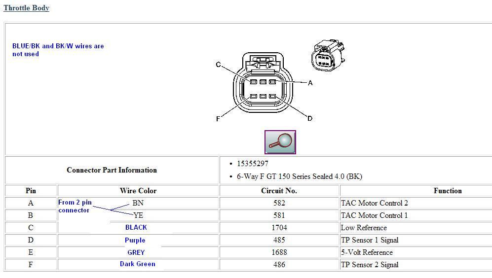
Yellow (circuit 581 - LS4 pin E) to (A) TAC Motor Control 2 (opposite 2006 CTSV - E67 w/90mm)
Brown (circuit 582 - LS4 pin F) to (B) TAC Motor Control 1 (opposite 2006 CTSV - E67 w/90mm)
Tan (circuit 2752 - LS4 pin C) to (C) Low Reference (confirmed 2006 CTSV - E67 w/90mm)
Gray (circuit 2701 - LS4 pin G) to (E) 5-Volt Reference (confirmed 2006 CTSV - E67 w/90mm)
Dark Green (circuit 485 - LS4 pin A) to (D) TP Sensor 1 Signal (confirmed 2006 CTSV - E67 w/90mm)
Purple (circuit 486 - LS4 pin D) to (F) TP Sensor 2 Signal (confirmed 2006 CTSV - E67 w/90mm)
Here is the TB pinout for the E67 LS4:
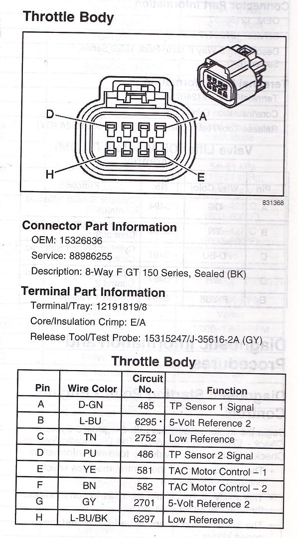
Here is a LS2 TB Pinout (ignore the wire color revisions) (the LS3 E67 GMPP pinouts are the same as this too):
So on a whim, I flipped the two tac motor wires and it started working like it should.
Here is how mine is wired up. I bolded the wiring differences between yours and mine.
Yellow (circuit 581 - LS4 pin E) to (A) TAC Motor Control 2 (opposite 2006 CTSV - E67 w/90mm)
Brown (circuit 582 - LS4 pin F) to (B) TAC Motor Control 1 (opposite 2006 CTSV - E67 w/90mm)
Tan (circuit 2752 - LS4 pin C) to (C) Low Reference (confirmed 2006 CTSV - E67 w/90mm)
Gray (circuit 2701 - LS4 pin G) to (E) 5-Volt Reference (confirmed 2006 CTSV - E67 w/90mm)
Dark Green (circuit 485 - LS4 pin A) to (D) TP Sensor 1 Signal (confirmed 2006 CTSV - E67 w/90mm)
Purple (circuit 486 - LS4 pin D) to (F) TP Sensor 2 Signal (confirmed 2006 CTSV - E67 w/90mm)
Here is the TB pinout for the E67 LS4:
Here is a LS2 TB Pinout (ignore the wire color revisions) (the LS3 E67 GMPP pinouts are the same as this too):
Trending Topics
I was able to get the car to start by wiring to your diagram but I still have codes P1516 and P2101 and my idle is jumping all over the place. I'm going to try swapping A and B and see it that helps. I appreciate your help in this matter.
LS1 Tech Stories
The Best V8 Stories One Small Block at Time

Gas Monkey Built a 6-Wheel Ferrari Testarossa With a Corvette LT4 Engine
Verdad Gallardo
7 Most Reliable High-Performance Engines GM Has Ever Built
Verdad Gallardo
Amazing '71 Camaro Restomod Is Modern Muscle Car Under the Skin
Verdad Gallardo
6 Common C5 Corvette Failures and What's Involved In Repairing Them
Pouria Savadkouei
Retro Modern Bandit Pontiac Trans AM Comes With Burt Reynolds' Autograph
Verdad Gallardo
Top 10 Greatest Cadillac V Series Performance Models Ever, Ranked
Pouria Savadkouei
Top 10 Most Powerful Chevy Trucks Ever Made!

Hennessey's New Supercharged Silverado ZR2 Has 700 HP
Verdad Gallardo
Coachbuilt N2A Anteros Is an LS2-Powered C6 Corvette In Italian Clothes
Verdad Gallardo Unless you tune your etc area scaler to 4,725.00 you with continue to have issues you should also disable the p2101 to no error reported
Also base iidle airflow might require some tweaking
Also base iidle airflow might require some tweaking
I have it wired:
Yellow (circuit 581 - LS4 pin E) to (B) TAC Motor Control 1
Brown (circuit 582 - LS4 pin F) to (A) TAC Motor Control 2
Tan (circuit 2752 - LS4 pin C) to (C) Low Reference
Gray (circuit 2701 - LS4 pin G) to (E) 5-Volt Reference
Dark Green (circuit 485 - LS4 pin A) to (D) TP Sensor 1 Signal
Purple (circuit 486 - LS4 pin D) to (F) TP Sensor 2 Signal
Interesting... once the snow/ice go away, I will use a jumper to verify exactly how mine is wired. I assume its the same as yours, but that isn't what my records show for some reason.