
Information on the LS4, DOD, and the 4T65E-HD
 08-09-2006, 12:17 AM
#1
Launching!
Thread Starter

Join Date: Dec 2005
Location: Brandon, MS
Posts: 214
Likes: 0
Received 0 Likes
on
0 Posts
Here is information on the engine and transmission in the LS4 front wheel drive cars. I have slightly condensed it to be more readable. The complete GM documention copied into Word Document format is attached. I re-read it several times, but if something doesn't sound right or make sense send me a PM. Any updates or suggestions are welcome.
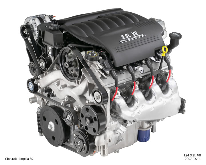
Generation IV 5.3L LS4 V8 Overview
The 5.3L LS4 shares the basic architecture of the 6.0L LS2. This includes an all aluminum block, six-bolt main bearing caps, deep-skirt cylinders, and a structural oil pan. It has the 243 casting LS6 heads with LS1 valve springs, which are good for 6200-6300 rpms.
Engineers had to mount this engine sideways so some changes were made. The crankshaft is shorten by 13 mm overall, 3 mm at the flywheel and 10 mm at the accessory drive. This was done to accommodate a more compact accessory drive. Instead of a 2 belt system there is only 1 long serpentine belt, even with this to save space there is only about 2 inches between the crankshaft pulley and the passenger side wheel well. The water pump is mounted off center with elongated passages to connect to the block (see picture). Also a rear facing intake manifold was designed. To ensure proper oiling during high-g cornering the oil pan has special baffles built in. Since Displacement on Demand uses oil for activation an oil pump with 31% more flow than previous LS2 type oil pumps is used.
Displacement: 325ci (5328cc)
Compression Ratio: 10:1 (premium fuel is recommended)
Bore x Stroke: 3.78" x 3.622" (96mm x 92mm)
Firing Order: 1-8-7-2-6-5-4-3
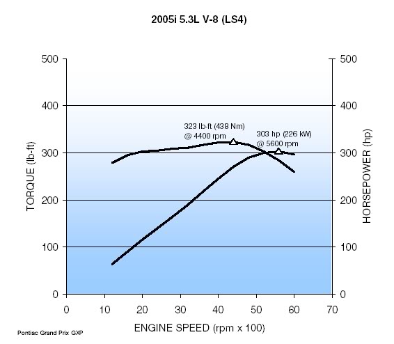
Horsepower: 303 hp @ 5600 rpm
Torque: 323 lb-ft @ 4400 rpm
Fuel Cut-off: 6100 rpm
5.3L LS4 V8
GM Dyno
Generation IV 5.3L LS4 V8 Overview
The 5.3L LS4 shares the basic architecture of the 6.0L LS2. This includes an all aluminum block, six-bolt main bearing caps, deep-skirt cylinders, and a structural oil pan. It has the 243 casting LS6 heads with LS1 valve springs, which are good for 6200-6300 rpms.
Engineers had to mount this engine sideways so some changes were made. The crankshaft is shorten by 13 mm overall, 3 mm at the flywheel and 10 mm at the accessory drive. This was done to accommodate a more compact accessory drive. Instead of a 2 belt system there is only 1 long serpentine belt, even with this to save space there is only about 2 inches between the crankshaft pulley and the passenger side wheel well. The water pump is mounted off center with elongated passages to connect to the block (see picture). Also a rear facing intake manifold was designed. To ensure proper oiling during high-g cornering the oil pan has special baffles built in. Since Displacement on Demand uses oil for activation an oil pump with 31% more flow than previous LS2 type oil pumps is used.
Displacement: 325ci (5328cc)
Compression Ratio: 10:1 (premium fuel is recommended)
Bore x Stroke: 3.78" x 3.622" (96mm x 92mm)
Firing Order: 1-8-7-2-6-5-4-3
Horsepower: 303 hp @ 5600 rpm
Torque: 323 lb-ft @ 4400 rpm
Fuel Cut-off: 6100 rpm
5.3L LS4 V8
GM Dyno
Last edited by BigMikeGXP; 08-31-2006 at 09:16 PM.
 08-09-2006, 12:51 AM
#2
Launching!
Thread Starter
Join Date: Dec 2005
Location: Brandon, MS
Posts: 214
Likes: 0
Received 0 Likes
on
0 Posts
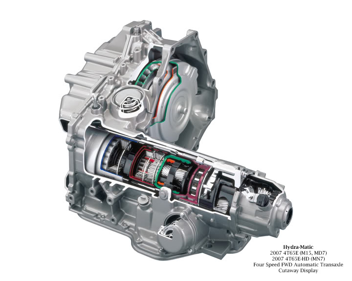
4T65E-HD Information
These are the upgrades that GM made to the MN7 version of the 4T65E-HD transmission to mate with the 5.3L LS4. Attached is the spec sheet for the MN7. One thing to add is that for the 2006 model year GM changed from Dexron V to Dexron VI fluid.
4T65E-HD
These are the upgrades that GM made to the MN7 version of the 4T65E-HD transmission to mate with the 5.3L LS4. Attached is the spec sheet for the MN7. One thing to add is that for the 2006 model year GM changed from Dexron V to Dexron VI fluid.
- 258mm, RI 15 Torque Converter
- Enhanced Heavy Duty 3.29 Final Drive
- 2.93 Effective Final Drive
- Transmission case for transmission mounted starter
- Net-formed Input Sun Gear
- Ceramic bead Peened Final Drive Sun Gear
- Input/Reaction Carrier Assembly
- Upgraded Drive sprocket Thrust washers (new for high speed capability)
http://www.clubgp.com/newforum/tm.asp?m=2276510
- Enhanced Heavy Duty 3.29 Final Drive
- 2.93 Effective Final Drive
- Transmission case for transmission mounted starter
- Net-formed Input Sun Gear
- Ceramic bead Peened Final Drive Sun Gear
- Input/Reaction Carrier Assembly
- Contour Hardened ReactionInternal Gear
- Input Carrier & Gear Asm. with lube grooves
- Shot-peened, Black-oxided Input Carrier Pinions
- Shot-peened Reaction Carrier Pinions
- Shot-peened Final Drive Sun shaft- Upgraded Drive sprocket Thrust washers (new for high speed capability)
http://www.clubgp.com/newforum/tm.asp?m=2276510
Last edited by BigMikeGXP; 08-31-2006 at 09:19 PM.
08-09-2006, 12:52 AM
#3
Launching!
Thread Starter
Join Date: Dec 2005
Location: Brandon, MS
Posts: 214
Likes: 0
Received 0 Likes
on
0 Posts
Displacement on Demand (DoD) General Information
The original name was Displacement on Demand (DoD). For the start of the 2006 model year GM renamed it Active Fuel Management (AFM).
During light load conditions while in 3rd or 4th gear the ECM will shut down cylinders 1, 4, 6, and 7 to put the engine in V4 mode. The engine will not enter V4 mode while cranking, idleing, or heavy acceleration. To shut down the cylinders the intake and exhaust valves stay closed and the fuel injectors stop feeding gas. The ECM times the shutdown so that each deactivated cylinder keeps the exhaust charge from the previous combustion cycle. This pressure on the pistons keeps them from rocking around in the cylinder causing vibration and oil consumption. Complete cylinder deactivation is accomplished in about 250 milliseconds.
The engine components involved in cylinder deactivation are the valve lifter oil manifold (VLOM) and special valve lifters. The VLOM consists of 4 solenoids that control oil flow to 8 valve lifters. Each solenoid goes with a certain cylinder and its 2 valve lifters.
When DoD is commanded on by the ECM the 4 solenoids energize and allow oil to flow to the valve lifters. The special valve lifters are made of an inner lifter and outer lifter with a spring loaded locking pin holding them together. When the oil gets to the lifters the pin is pushed out of place and the inner and outer part of the lifter are allowed to move seperately. The camshaft is still pushing on the outer part of the lifter, but the inner part of the lifter is no longer pushing up on the pushrod. This keeps the intake and exhaust valve shut permanently until the ECM commands DoD off. At this point the solenoids stop oil flow to the lifters and the spring loaded lifter pins lock back into place, causing the lifters to return to normal operation.
Last edited by BigMikeGXP; 08-31-2006 at 09:18 PM.
08-09-2006, 01:02 AM
#4
Launching!
Thread Starter
Join Date: Dec 2005
Location: Brandon, MS
Posts: 214
Likes: 0
Received 0 Likes
on
0 Posts
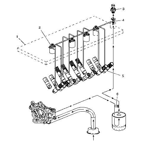
Found this over at Fastfieros.com... it discribes in greater detail the operation of the VLOM and valve lifters.
http://www.fastfieros.com/tech/dod_oil_path.htm
http://www.fastfieros.com/tech/dod_oil_path.htm
The valve lifter oil manifold assembly (1) is bolted to the top of the engine block beneath the intake manifold assembly. The oil manifold consists of four electrically operated and normally-closed solenoids (2). Each solenoid directs the flow of pressurized engine oil to the DoD intake and exhaust valve lifters (5). The oil pressure relief valve (6), located in the left rear area of the oil pan, regulates engine oil pressure to the lubrication system and the oil manifold.
When enabling conditions are met for DoD operation, the PCM will ground each solenoid control circuit in firing order sequence, allowing current to flow through the solenoid windings. With the windings energized, the solenoid valves open and direct pressurized engine oil through the manifold into eight vertical passages in the engine block lifter valley. The eight vertical passages, two per cylinder, direct pressurized oil to the valve lifter bores of the cylinders to be deactivated. When vehicle operating conditions require a return to V8 mode, the PCM will turn OFF the ground circuit for the solenoids, allowing the solenoid valves to close. When the solenoid valves are closed, remaining oil pressure is exhausted through the bleed passages of the manifold into the engine block lifter valley. The housing of the oil manifold incorporates several oil bleed passages that continually purge trapped air from the manifold and engine block.
To help control contamination within the DoD hydraulic system, a small replaceable oil filter (4) is located in the manifold oil inlet passage. The oil pressure sensor (3) monitors engine oil pressure and provides information to the PCM.
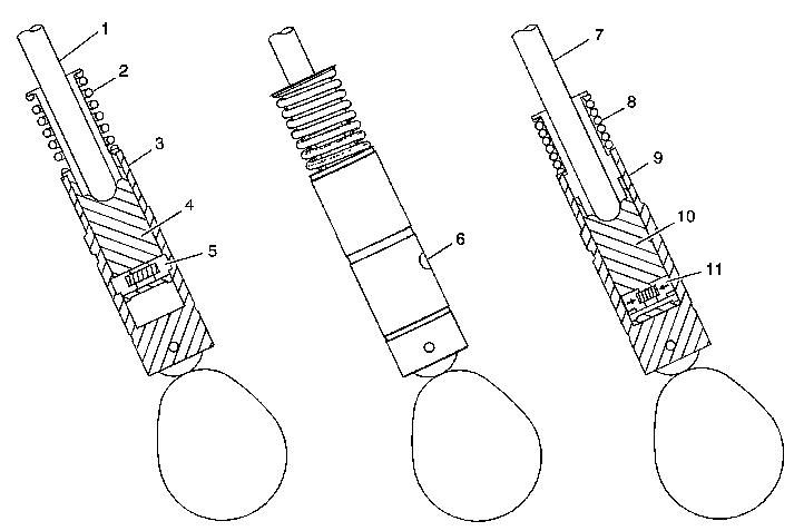
When operating in V8 mode, the DoD valve lifters function similar to the non-DoD valve lifters. The DoD oil manifold solenoids are in the closed position with no pressurized oil directed to the valve lifters. The pushrod (1) travels upward and downward to actuate the rocker arm and valve. The spring loaded locking pins (5) of the lifter are extended outward and mechanically lock the pin housing (4) to the outer body of the valve lifter (3).
When the DoD system is commanded ON, the PCM will direct the solenoids of the oil manifold to open and direct pressurized oil to the valve lifters. Oil travels through the manifold and engine block oil galleries and enters the inlet port (6) of the valve lifter.
When operating in V4 mode, pressurized oil forces the locking pins (11) inward. The pushrod (7) remains in a constant position and does not travel upward and downward. The outer body of the lifter (9) moves upward and downward independently from the pin housing (10). The valve lifter spring (8) retains tension on the valve train components to eliminate valve train noise.
When the DoD system is commanded OFF, the PCM directs the solenoids of the oil manifold to close, stopping the flow of pressurized oil to the valve lifters. The oil pressure within the lifter will decrease and the locking pins will move outward to mechanically lock the pin housing and outer body.
Last edited by BigMikeGXP; 08-31-2006 at 09:14 PM.
08-09-2006, 02:01 AM
#5
This thread is for the specifics of the LS4 Engine.
Engine Type V8
Displacement 5.3L 325 CID
RPO LS4
VIN C
Bore 96.0-96.018 mm 3.779-3.78 in
Stroke 92.0 mm 3.622 in
Compression Ratio 9.9:1
Firing Order 1-8-7-2-6-5-4-3
Displacement on Demand Cylinders 1-4-6-7
Spark Plug Gap 1.02 mm 0.04 in
Block
Camshaft Bearing Bore 1 and 5 Diameter 59.58-59.63 mm 2.345-2.347 in
Camshaft Bearing Bore 2 and 4 Diameter 59.08-59.13 mm 2.325-2.327 in
Camshaft Bearing Bore 3 Diameter 58.58-58.63 mm 2.306-2.308 in
Crankshaft Main Bearing Bore Diameter 69.871-69.889 mm 2.75-2.751 in
Crankshaft Main Bearing Bore Out-of-Round 0.006 mm 0.0002 in
Cylinder Bore Diameter 96.0-96.018 mm 3.779-3.78 in
Cylinder Head Deck Height - Measuring from the Centerline of Crankshaft to the Deck Face 234.57-234.82 mm 9.235-9.245 in
Cylinder Head Deck Surface Flatness - Measured Within a 152.4 mm (6.0 in) Area 0.11 mm 0.004 in
Cylinder Head Deck Surface Flatness - Measuring the Overall Length of the Block Deck 0.22 mm 0.008 in
Valve Lifter Bore Diameter 21.417-21.443 mm 0.843-0.844 in
Camshaft
Camshaft End Play 0.025-0.305 mm 0.001-0.012 in
Camshaft Journal Diameter 54.99-55.04 mm 2.164-2.166 in
Camshaft Bearing Diameter 55.063-55.088 mm 2.1678-2.1688 in
Camshaft Journal-to-Bearing Clearance 0.023-0.098 mm 0.0009-0.0038 in
Camshaft Journal Out-of-Round 0.025 mm 0.001 in
Camshaft Lobe Lift - Intake - Non Displacement on Demand Cylinders 7.2 mm 0.283 in
Camshaft Lobe Lift - Intake - Displacement on Demand Cylinders 7.33 mm 0.289 in
Camshaft Lobe Lift - Exhaust - Non Displacement on Demand Cylinders 7.2 mm 0.283 in
Camshaft Lobe Lift - Exhaust - Displacement on Demand Cylinders 7.33 mm 0.289 in
Camshaft Runout - Measured at the Intermediate Journals 0.05 mm 0.002 in
Connecting Rod
Connecting Rod Bearing Clearance - Production 0.023-0.065 mm 0.0009-0.0025 in
Connecting Rod Bearing Clearance - Service 0.023-0.076 mm 0.0009-0.003 in
Connecting Rod Bore Diameter - Bearing End 56.505-56.525 mm 2.224-2.225 in
Connecting Rod Bore Out-of-Round - Bearing End - Production 0.004-0.008 mm 0.00015-0.0003 in
Connecting Rod Bore Out-of-Round - Bearing End - Service 0.004-0.008 mm 0.00015-0.0003 in
Connecting Rod Side Clearance 0.11-0.51 mm 0.00433-0.02 in
Crankshaft
Connecting Rod Journal Diameter - Production 53.318-53.338 mm 2.0991-2.0999 in
Connecting Rod Journal Diameter - Service 53.308 mm 2.0987 in
Connecting Rod Journal Out-of-Round - Production 0.005 mm 0.0002 in
Connecting Rod Journal Out-of-Round - Service 0.01 mm 0.0004 in
Connecting Rod Journal Taper - Maximum for 1/2 of Journal Length - Production 0.005 mm 0.0002 in
Connecting Rod Journal Taper - Maximum for 1/2 of Journal Length - Service 0.02 mm 0.00078 in
Crankshaft End Play 0.04-0.2 mm 0.0015-0.0078 in
Crankshaft Main Bearing Clearance - Production 0.02-0.052 mm 0.0008-0.0021 in
Crankshaft Main Bearing Clearance - Service 0.02-0.065 mm 0.0008-0.0025 in
Crankshaft Main Journal Diameter - Production 64.992-65.008 mm 2.558-2.559 in
Crankshaft Main Journal Diameter - Service 64.992 mm 2.558 in
Crankshaft Main Journal Out-of-Round - Production 0.003 mm 0.000118 in
Crankshaft Main Journal Out-of-Round - Service 0.008 mm 0.0003 in
Crankshaft Main Journal Taper - Production 0.01 mm 0.0004 in
Crankshaft Main Journal Taper - Service 0.02 mm 0.00078 in
Crankshaft Rear Flange Runout 0.05 mm 0.002 in
Crankshaft Reluctor Ring Runout - Measured 1.0 mm (0.04 in) Below Tooth Diameter 0.7 mm 0.028 in
Crankshaft Thrust Surface - Production 26.14-26.22 mm 1.029-1.0315 in
Crankshaft Thrust Surface - Service 26.22 mm 1.0315 in
Crankshaft Thrust Surface Runout 0.025 mm 0.001 in
Cylinder Head
Cylinder Head Height/Thickness - Measured from the Cylinder Head Deck to the Valve Rocker Arm Cover Seal Surface 120.2 mm 4.732 in
Surface Flatness - Block Deck - Measured Within a 152.4 mm (6.0 in) Area 0.08 mm 0.003 in
Surface Flatness - Block Deck - Measuring the Overall Length of the Cylinder Head 0.1 mm 0.004 in
Surface Flatness - Exhaust Manifold Deck 0.13 mm 0.005 in
Surface Flatness - Intake Manifold Deck 0.08 mm 0.0031 in
Valve Guide Installed Height - Measured from the Spring Seat Surface to the Top of the Guide 17.32 mm 0.682 in
Intake Manifold
Surface Flatness - Measured at Gasket Sealing Surfaces and Measured Within a 200 mm (7.87 in) Area that Includes 2 Runner Port Openings 0.3 mm 0.118 in
Lubrication System
Oil Capacity - with Filter 5.7 liters 6.0 quarts
Oil Capacity - without Filter 5.2 liters 5.5 quarts
Oil Pressure - Minimum - Hot 41 kPa at 1,000 engine RPM 6 psig at 1,000 engine RPM
124 kPa at 2,000 engine RPM 18 psig at 2,000 engine RPM
165 kPa at 4,000 engine RPM 24 psig at 4,000 engine RPM
Displacement on Demand Relief Valve Oil Pressure - as Measured at Oil Pressure Sensor Location 379-517 kPa 55-75 psig
Maximum Maximum
Oil Pan
Front Cover Alignment - at Oil Pan Surface 0.0-0.5 mm 0.0-0.02 in
Crankshaft Rear Oil Seal Housing Alignment - at Oil Pan Surface 0.0-0.5 mm 0.0-0.02 in
Oil Pan Alignment - to Rear of Engine Block at Transmission Bell Housing Mounting Surface 0.0-0.1 mm 0.0-0.004 in
Piston Rings
Piston Ring End Gap - First Compression Ring - Measured in Cylinder Bore - Production 0.23-0.44 mm 0.009-0.017 in
Piston Ring End Gap - First Compression Ring - Measured in Cylinder Bore - Service 0.23-0.5 mm 0.009-0.0196 in
Piston Ring End Gap - Second Compression Ring - Measured in Cylinder Bore - Production 0.44-0.7 mm 0.017-0.027 in
Piston Ring End Gap - Second Compression Ring - Measured in Cylinder Bore - Service 0.44-0.76 mm 0.0173-0.03 in
Piston Ring End Gap - Oil Control Ring - Measured in Cylinder Bore - Production 0.18-0.75 mm 0.007-0.029 in
Piston Ring End Gap - Oil Control Ring - Measured in Cylinder Bore - Service 0.18-0.81 mm 0.007-0.032 in
Piston Ring to Groove Clearance - First Compression Ring - Production 0.04-0.085 mm 0.00157-0.00335 in
Piston Ring to Groove Clearance - First Compression Ring - Service 0.04-0.085 mm 0.00157-0.00335 in
Piston Ring to Groove Clearance - Second Compression Ring - Production 0.04-0.078 mm 0.00157-0.0031 in
Piston Ring to Groove Clearance - Second Compression Ring - Service 0.04-0.078 mm 0.00157-0.0031 in
Piston Ring to Groove Clearance - Oil Control Ring - Production 0.012-0.2 mm 0.0005-0.0078 in
Piston Ring to Groove Clearance - Oil Control Ring - Service 0.012-0.2 mm 0.0005-0.0078 in
Pistons and Pins
Piston - Piston Diameter - Measured Over Skirt Coating 96.002-96.036 mm 3.779-3.78 in
Piston - Piston to Bore Clearance - Production -0.036 to +0.016 mm -0.0014 to +0.0006 in
Piston - Piston to Bore Clearance - Service Limit with Skirt Coating Worn Off 0.071 mm 0.0028 in
Pin - Piston Pin Clearance-to-Piston Pin Bore - Production 0.002-0.01 mm 0.00008-0.00004 in
Pin - Piston Pin Clearance-to-Piston Pin Bore - Service 0.002-0.015 mm 0.00008-0.00006 in
Pin - Piston Pin Fit in Connecting Rod Bore - Production 0.007-0.02 mm 0.00027-0.00078 in
Pin - Piston Pin Fit in Connecting Rod Bore - Service 0.007-0.022 mm 0.00027-0.00086 in
Pin - Piston Pin Diameter 23.997-24.0 mm 0.9447-0.9448 in
Valve System
Valves - Valve Face Angle 45 degrees
Valves - Valve Face Width 1.25 mm 0.05 in
Valves - Valve Lash Net Lash - No Adjustment
Valves - Valve Lift - Intake - Non Displacement on Demand (DoD) 12.24 mm 0.482 in
Valves - Valve Lift - Exhaust - Non Displacement on Demand (DoD) 12.24 mm 0.482 in
Valves - Valve Lift - Intake - Displacement on Demand (DoD) 12.46 mm 0.49 in
Valves - Valve Lift - Exhaust - Displacement on Demand (DoD) 12.46 mm 0.49 in
Valves - Valve Lift - Exhaust 11.85 mm 0.466 in
Valves - Valve Seat Angle 46 degrees
Valves - Valve Seat Runout 0.05 mm 0.002 in
Valves - Valve Seat Width - Exhaust 1.78 mm 0.07 in
Valves - Seat Width - Intake 1.02 mm 0.04 in
Valves - Valve Stem Diameter - Production 7.955-7.976 mm 0.313-0.314 in
Valves - Valve Stem Diameter - Service 7.95 mm 0.313 in
Valves - Valve Stem-to-Guide Clearance - Production - Intake 0.025-0.066 mm 0.001-0.0026 in
Valves - Valve Stem-to-Guide Clearance - Service - Intake 0.093 mm 0.0037 in
Valves - Valve Stem-to-Guide Clearance - Production - Exhaust 0.025-0.066 mm 0.001-0.0026 in
Valves - Valve Stem-to-Guide Clearance - Service - Exhaust 0.093 mm 0.0037 in
Rocker Arms - Valve Rocker Arm Ratio 1.70:1
Valve Springs - Valve Spring Free Length 52.9 mm 2.08 in
Valve Springs - Valve Spring Installed Height 45.75 mm 1.8 in
Valve Springs - Valve Spring Load - Closed 340 N at 45.75 mm 76 lb at 1.8 in
Valve Springs - Valve Spring Load - Open 980 N at 33.55 mm 220 lb at 1.32 in
Last edited by 91parkave; 02-23-2015 at 06:59 AM.
 08-09-2006, 05:00 PM
#7
I hope that serp. belt lasts awhile, cause it is going to be a pain to replace. One thing that I did notice is I get way better gas mileage going 60 - 65 miles an hour on the expressway compared to 70 - 75. 30-32 mpg compared to 22 - 24 mpg
Trending Topics
08-10-2006, 01:30 AM
#8
Launching!
Thread Starter
Join Date: Dec 2005
Location: Brandon, MS
Posts: 214
Likes: 0
Received 0 Likes
on
0 Posts
Originally Posted by jabronie78
I hope that serp. belt lasts awhile, cause it is going to be a pain to replace. One thing that I did notice is I get way better gas mileage going 60 - 65 miles an hour on the expressway compared to 70 - 75. 30-32 mpg compared to 22 - 24 mpg
Yeah the DOD stays on a lot more around 65. Its weird how the wind drag on the car increases so much past 72-73 mph.
08-13-2006, 08:25 PM
#10
On The Tree

Join Date: Jun 2006
Posts: 146
Likes: 0
Received 0 Likes
on
0 Posts
So in v4 mode is the motor just dragging the other 4 pistons or does the crankshaft somehow split and make them stop moving? if the motor is dragging 4 pistons i dont see how it helps gas mileage.
08-14-2006, 12:08 AM
#11
Launching!
Thread Starter
Join Date: Dec 2005
Location: Brandon, MS
Posts: 214
Likes: 0
Received 0 Likes
on
0 Posts
Nothing changes on the crankshaft. The other 4 cylinders are not pumping with the valves closed. Effectively there is just extra rotating mass in V4 mode, which is not a loss of energy because it is already rotating. Any loss of energy would be frictional... which will always be there. So it does help gas mileage in conditions where the horsepower of 8 cylinders is overkill... such as cruising.
I kinda wish they would have made it possible to run 4, 6, or 8 cylinders. The 6 would be better on hills and running at speeds of around 75-80.
I kinda wish they would have made it possible to run 4, 6, or 8 cylinders. The 6 would be better on hills and running at speeds of around 75-80.
08-17-2006, 09:38 PM
#12
Staging Lane

Join Date: Dec 2004
Posts: 91
Likes: 0
Received 0 Likes
on
0 Posts

Mike is right on with this. I would only add that rather than just dragging the pistons in V4 mode as Bo states, the engine is operating slightly different. As Mike said, the valves are closed in V4 mode. This traps a spent charge in the chamber and causes the charge to act as an air spring. This helps recover some of the rotational energy so that the crank is not dragging completely dead weight. As stated in the documentation, there are also other advantages to doing this. The system will also cycle the charge for every ten minutes of V4 operation by going into V8 mode for one minute.
Chip
Chip
 10-18-2006, 10:52 PM
#14
TECH Fanatic
Join Date: Oct 2006
Posts: 1,190
Likes: 0
Received 0 Likes
on
0 Posts
Thanks also from me Mike. I appreciate your hard work there.
The DoD now scares the crap out of me for long term reliability. I get 24 mpg instead of 22 mpg in V8 mode. NOTHING like the 28 mpg / highway on the sticker (well, it DOES get 28 when I'm on a country road where the speed limit is 55). Not on the 70 mph highway.
Call me stupid for purchasing a car without looking at all the facts first.
Confession - I really bought my red Monte SS because it's the first REAL Monte Carlo SS since '88 (I had an '85 and spent 135K miles with the thing) and really represents what a Monte Carlo SS is. The V8 and the new facias - GM really did it right this time! Hot looking car - it get lots of compliments. Reality - $30,000 impulse buy. 22 mpg for this fun of a car is OK to me.
A month and a half later I find your site, with your indepth description of what DoD is, nothing like the Cadillac Northstar "limp home mode" that I thought shutting down cylinders meant.
"The special valve lifters are made of an inner lifter and outer lifter with a spring loaded locking pin holding them together" screams FAILURE AFTER WARRANTY. No big deal, things will break. We're car guys, we beat on our equipment, it will break, it's justifies us to rebuild with the mods we will do after warranty anyway.
The question is then ... can I get rid of these DoD parts and make it like a regular LSx engine when it fails?
I really don't need the BS 8 switch to 4, back to 8, back to 4, now 8, 4, 8, 8, 4 .. blah blah crap for 2 measly miles to the gallon. What did I "pay" for this technology??? WAY TOO MUCH for 2 mpg!!!
Update - looked under the hood: my engine cover says "Displacement on Demand". LS4, Rev 1 ... SWEET!!! I guess my car will be one of the MCSS's listed to "avoid purchasing" in the future.
Last edited by Kazmaniac; 10-18-2006 at 11:19 PM.
10-18-2006, 11:50 PM
#15
Launching!
Thread Starter
Join Date: Dec 2005
Location: Brandon, MS
Posts: 214
Likes: 0
Received 0 Likes
on
0 Posts
They have been testing DoD for years actually. I remember hearing about it back in 02 I think. Plus we are not the first vehicle to use it. Im sure GM did their homework. If the engine were left in stock form you should have no trouble. Start modding and you never know though.
With that said... im not a big fan of DoD. I think it works great at speeds of 35-60 mph. But at interstate levels (above 70 mph) it really doesn't help.
I did some logging with HP Tuners on the interstate. The injector pulse width doubles when DoD mode is activated. You are only pumping with 4 injectors instead 8... but if the pumping rate doubles for the 4 that are still active then simple math says you are using about the same amount of gas.
10-19-2006, 12:57 AM
#16
TECH Fanatic
Join Date: Oct 2006
Posts: 1,190
Likes: 0
Received 0 Likes
on
0 Posts
I would agree with your fuel data logging theory Michael. In my case I would just keep all 8 on then.
I need to get HP Tuners ... I assume it will void the warranty if I turn off the DoD before 36K?
I need to get HP Tuners ... I assume it will void the warranty if I turn off the DoD before 36K?
10-22-2006, 06:50 PM
#17
Staging Lane
Join Date: Oct 2006
Location: Pittsburgh
Posts: 92
Likes: 0
Received 0 Likes
on
0 Posts
Well, I'm just outside of Pittsburgh, and at a local sams club tire shop there was this Monte SS with the DoD 5.3 in it. It was from a local dealership who actually told me that they got this car new, shipped in, ordered for a customer... When it came it pooped out after like 1200 miles and got brought in. After three months of down time they decided they can't use it, they simply cant get it to run... EVER! So now it sits as a show piece (of crap) at the tire department at sams club.
10-22-2006, 09:11 PM
#18
Teching In

Join Date: Aug 2005
Posts: 17
Likes: 0
Received 0 Likes
on
0 Posts
gm has been working on DoD for a long time starting with the northstarts a number of years ago... they started it back up again for a few reasons:
1) ORIGINALLY for the light trucks to give them a few extra mpg on paper which keeps them epa friendly and makes for a good sales pitch. not sure why they are putting them in cars though.
2) drive by wire and other such electronics are finally up to par with what is needed for the system to work. the old caddy owners complained ALOT about the noticeable drop in power and engine dbs when the motors would switch from 8-6-4. new electronics allow 'seamless' opening of the tb and all the other little things that need to happen when you drop some cylinders.
the reason they dont go to v6 mode anymore is vibration (another complaint of old n.star owners) v6 4 cycle engines have an inherent imbalance that the general has since combated with a large counter shaft in their current v6s for trucks and boats (vortec).
i purposefully bought a year older truck when I bought my burban this year just to avoid the DOD. I'm not worried about 1-2 mpg in a 6000? lbs vehicle, i can get that just by keeping my right foot out of it. I am more worried about the valve body up in the lifter valley... that is essentially a very precise automatic trans. wonder how much dirty oil and sludge they let build up in these motors during testing.
save the exotic stuff for the vette, keep the tried and true stuff on the passenger cars and trucks so i can get 200k out of this truck too.
10-23-2006, 05:14 PM
#19
Staging Lane
Join Date: Oct 2006
Location: Pittsburgh
Posts: 92
Likes: 0
Received 0 Likes
on
0 Posts
I dont see where the imbalance would come from if all the cylinders are still charged with an exhaust pressure... and all still rotating. As long as its balanced to begin with it should be balanced no matter how many are "firing".
10-24-2006, 12:19 PM
#20
Teching In
Join Date: Aug 2005
Posts: 17
Likes: 0
Received 0 Likes
on
0 Posts
its not that the assembly itself is out of balance, it has to do with the compression and power strokes being odd fired and the internal harmonics that result.
look at the diagram above that shows which 4 cylinders are used. see how the counter weights look all symmetrical etc to each other. now sit down and try to figure out which 6 cylinders you would want to use to get that same exact 'balance' of counter weight position vs. stroke. hence the counter shaft.
check out the diagram of the 4.3l (and the I6 for that matter b/c they used it on that motor too I think) on GMs site (look in the marine section) nice big fat counter shaft that acts like a specifically balanced and engineered harmonic dampener.