


24x pinout questions
 24x pinout questions
 Okay, today I started the task of building my harness for my 24x conversion. The harness is of a 1997 M6 car. FIRST I'll apologize for the long post...here's my questions:
1. LS1 connector C1 BLUE pin #2, crankshaft position sensor 12v ref, BP Automotive shows lt green color but no origin on 97 LT1 harness. Do I add from new wire?
2. LS1 connector C1 BLUE pin #19, PCM ignition #1, BP Automotive shows LT1 location black 30 & blue 3. I need to tie them together and put into C1-19?
3. LS1 connector C1 BLUE pin #20, PCM battery positive voltage, BP Automotive shows LT1 location black 15 & black 31, also shows C1 BLUE pin #57 as same. I need just to put one in one and the other in the other?
4. LS1 connector C1 BLUE pin #79, BP shows as 3-2 shift solenoid control at LT1 connector Black 13 (white wire), I've found it as skip shift solenoid control (gray wire, which it IS). Still correct? just AT vs MT variance and leave alone?
5. LS1 connector C2 RED pins 6&8, PC solenoid valve high & low (respectively) control, empty locations in my LT1 harness. AT functions?
6. LS1 connector C2 RED pin #57, IAT sensor low reference, LT1 location black 16 (black wire), was empty slot in my LT1 harness. NOT thinking it should be???
7. LS1 connector C2 RED uses LT1 blue 6 in pin #2 & #44. #2 being TCC power solenoid valve control (A/T?) and #44 being reverse lockout solenoid (M/T). I need to leave #2 empty and use blue 6 in C2 RED #44, correct?
These pins do not have locations in the BP Automotive Conversion sheet. Are they ALL eliminated? All are shown from LT1 locations:
Clear 11-TCS active (no rear reluctor ring)
3-HO2 signal low B1S2 (don't have)
4-HO2 signal high B1S2 (don't have)
17-HO2 signal low B2S2 (don't have)
18-HO2 signal high B2S2 (don't have)
Blue 10-evap canister purge solenoid valve control (does this stay??)
15-skip shift lamp control
20-output field service enable
24-A/C evap temp sensor signal (A/C eliminated anyway)
30-serial data (does this stay??)
Black 2-low res signal----------------| opti
5-ignition control | crap
14-distrubitor ignition feed | all
20-high resolution signal--------| gone?
23-evap canister vent solenoid control (does this go to C2 RED pin45?)
Red 14-air pump relay control
23-TCS spark retard request
AND throughout all my research I could not find ANYTHING on what these wires go to:
Red 1, 9, & 12.
I used BP Automotive's DIY 24x conversion PCM comparison sheet, "24x LT1 to LS1 repin compilation" thread on LS1TECH.com, and shbox.com's 1995 PCM pinout for reference.
THANKS!
1. LS1 connector C1 BLUE pin #2, crankshaft position sensor 12v ref, BP Automotive shows lt green color but no origin on 97 LT1 harness. Do I add from new wire?
2. LS1 connector C1 BLUE pin #19, PCM ignition #1, BP Automotive shows LT1 location black 30 & blue 3. I need to tie them together and put into C1-19?
3. LS1 connector C1 BLUE pin #20, PCM battery positive voltage, BP Automotive shows LT1 location black 15 & black 31, also shows C1 BLUE pin #57 as same. I need just to put one in one and the other in the other?
4. LS1 connector C1 BLUE pin #79, BP shows as 3-2 shift solenoid control at LT1 connector Black 13 (white wire), I've found it as skip shift solenoid control (gray wire, which it IS). Still correct? just AT vs MT variance and leave alone?
5. LS1 connector C2 RED pins 6&8, PC solenoid valve high & low (respectively) control, empty locations in my LT1 harness. AT functions?
6. LS1 connector C2 RED pin #57, IAT sensor low reference, LT1 location black 16 (black wire), was empty slot in my LT1 harness. NOT thinking it should be???
7. LS1 connector C2 RED uses LT1 blue 6 in pin #2 & #44. #2 being TCC power solenoid valve control (A/T?) and #44 being reverse lockout solenoid (M/T). I need to leave #2 empty and use blue 6 in C2 RED #44, correct?
These pins do not have locations in the BP Automotive Conversion sheet. Are they ALL eliminated? All are shown from LT1 locations:
Clear 11-TCS active (no rear reluctor ring)
3-HO2 signal low B1S2 (don't have)
4-HO2 signal high B1S2 (don't have)
17-HO2 signal low B2S2 (don't have)
18-HO2 signal high B2S2 (don't have)
Blue 10-evap canister purge solenoid valve control (does this stay??)
15-skip shift lamp control
20-output field service enable
24-A/C evap temp sensor signal (A/C eliminated anyway)
30-serial data (does this stay??)
Black 2-low res signal----------------| opti
5-ignition control | crap
14-distrubitor ignition feed | all
20-high resolution signal--------| gone?
23-evap canister vent solenoid control (does this go to C2 RED pin45?)
Red 14-air pump relay control
23-TCS spark retard request
AND throughout all my research I could not find ANYTHING on what these wires go to:
Red 1, 9, & 12.
I used BP Automotive's DIY 24x conversion PCM comparison sheet, "24x LT1 to LS1 repin compilation" thread on LS1TECH.com, and shbox.com's 1995 PCM pinout for reference.
THANKS!

Launching!
Joined: Apr 2013
Posts: 225
Likes: 0
Try this page for pinouts.
http://lt1swap.com/lt1_pcm_pinout.htm
That page and the diagram from ondemand show that the ckp signal is on the red (C1) connector pin 1.
http://lt1swap.com/lt1_pcm_pinout.htm
That page and the diagram from ondemand show that the ckp signal is on the red (C1) connector pin 1.
C1 BLUE connector, pin #2, Crank Position Sensor 12v Ref, What is its origin? Everything I look at shows the origin as blank.
lt1swap.com/lt1_pcm_pinout.htm as well as others similar show retaining the following wires as "wires to keep for external connections", BUT the DIY pinout from BP Automotive doesn't show keeping them at all. Ideas where they go?
Blue 20 -- wht/blk -- 448 -- output/field service enable (diag port)
Blue 30 -- tan -- 800 -- serial data (UART) (diag port)
Black 2 --red/blk -- 453 -- low res signal
Black 5 -- wht -- 423 -- ignition control
Black 14 -- red -- 631 -- distributor ignition feed
Black 20 -- ppl/wht -- 430 --high res signal
Thanks in advance.
Try searching threads from "lethalbird" he had a good thread aswell. I will have to try and dig up my notes and see what goes where. The service adld port tan wire gets sliced into the purple wire going into your aldl port. The other stuff dont recall off the top of my head. The output field service im pretty sure was deleted.
95mysticta -- I dug through your posts on your 24x harness build and found the answers to most of my questions, thanks! I still have a few unanswered that maybe you'd be willing to work with me on personally?
C1 BLUE connector, pin #2, Crank Position Sensor 12v Ref, What is its origin? Everything I look at shows the origin as blank.
lt1swap.com/lt1_pcm_pinout.htm as well as others similar show retaining the following wires as "wires to keep for external connections", BUT the DIY pinout from BP Automotive doesn't show keeping them at all. Ideas where they go?
Blue 20 -- wht/blk -- 448 -- output/field service enable (diag port)
Blue 30 -- tan -- 800 -- serial data (UART) (diag port)
Black 2 --red/blk -- 453 -- low res signal
Black 5 -- wht -- 423 -- ignition control
Black 14 -- red -- 631 -- distributor ignition feed
Black 20 -- ppl/wht -- 430 --high res signal
Thanks in advance.
C1 BLUE connector, pin #2, Crank Position Sensor 12v Ref, What is its origin? Everything I look at shows the origin as blank.
lt1swap.com/lt1_pcm_pinout.htm as well as others similar show retaining the following wires as "wires to keep for external connections", BUT the DIY pinout from BP Automotive doesn't show keeping them at all. Ideas where they go?
Blue 20 -- wht/blk -- 448 -- output/field service enable (diag port)
Blue 30 -- tan -- 800 -- serial data (UART) (diag port)
Black 2 --red/blk -- 453 -- low res signal
Black 5 -- wht -- 423 -- ignition control
Black 14 -- red -- 631 -- distributor ignition feed
Black 20 -- ppl/wht -- 430 --high res signal
Thanks in advance.
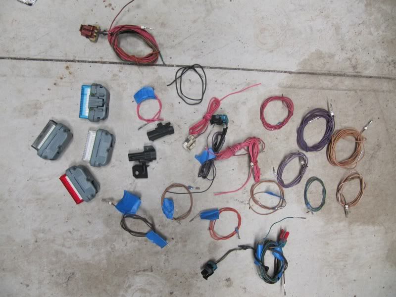
keep in mind that you are wiring for the ls1 computer not the lt1 computer. You only need what the ls1 computer needs (spark, fuel, oil pressure, voltage, maf, crank, cam) on the engine side and then all of the gauges on the inside.
Lot of your lt1 harness goes to trash...
 [/URL]
Lot of your lt1 harness goes to trash...
[/URL] 95mysticta -- I dug through your posts on your 24x harness build and found the answers to most of my questions, thanks! I still have a few unanswered that maybe you'd be willing to work with me on personally?
C1 BLUE connector, pin #2, Crank Position Sensor 12v Ref, What is its origin? Everything I look at shows the origin as blank.
lt1swap.com/lt1_pcm_pinout.htm as well as others similar show retaining the following wires as "wires to keep for external connections", BUT the DIY pinout from BP Automotive doesn't show keeping them at all. Ideas where they go?
Blue 20 -- wht/blk -- 448 -- output/field service enable (diag port)
Blue 30 -- tan -- 800 -- serial data (UART) (diag port)
Black 2 --red/blk -- 453 -- low res signal
Black 5 -- wht -- 423 -- ignition control
Black 14 -- red -- 631 -- distributor ignition feed
Black 20 -- ppl/wht -- 430 --high res signal
Thanks in advance.
C1 BLUE connector, pin #2, Crank Position Sensor 12v Ref, What is its origin? Everything I look at shows the origin as blank.
lt1swap.com/lt1_pcm_pinout.htm as well as others similar show retaining the following wires as "wires to keep for external connections", BUT the DIY pinout from BP Automotive doesn't show keeping them at all. Ideas where they go?
Blue 20 -- wht/blk -- 448 -- output/field service enable (diag port)
Blue 30 -- tan -- 800 -- serial data (UART) (diag port)
Black 2 --red/blk -- 453 -- low res signal
Black 5 -- wht -- 423 -- ignition control
Black 14 -- red -- 631 -- distributor ignition feed
Black 20 -- ppl/wht -- 430 --high res signal
Thanks in advance.
keep in mind that you are wiring for the ls1 computer not the lt1 computer. You only need what the ls1 computer needs (spark, fuel, oil pressure, voltage, maf, crank, cam) on the engine side and then all of the gauges on the inside.
Lot of your lt1 harness goes to trash...
[/URL]
Lot of your lt1 harness goes to trash...
[/URL]Black 2, 5,14, & 20 all seem as though they should be axed. They feed the opti which is gone as well as the ign control module, gone as well. Trash them, right?
Blue 20 & 30... 20 seems to be common consensus to trash, while some say 30 (tan wire) can go to Blue 57 on the 0411? gone or stay?
C1 BLUE connector, pin #2, Crank Position Sensor 12v Ref, What is its origin? Everything I look at shows the origin as blank. Even the BP paperwork I received, and I'm not positive I received it all, shows its origin as BLANK! I am awaiting the CKP harness from BP now...does this wire run FROM the CKP sensor to pin #2? much like C1 Blue #12 & #21? More simple put, are these the 3 wires that run from the CKP sensor to the PCM in the factory LT1 harness just pinned into the updated connector?
And on a separate rant, if the 96-97 GM CKP sensor plug wont fit the EFIConnection 24x CKP sensor, anyone have any idea why BP doesn't include the necessary connector with the kit? Just struck me as odd when I tried to plug the connector onto the sensor....
Trending Topics
when i did this, i stripped the entire harness down so i could route it better. you are spending way too much time thinking where the lt1 stuff goes, you only need to focus on what the 411 needs. start with the 411, do the coils, ignition, crank, cam, maf, power ground and the rest will get easier as you go.
LS1 Tech Stories
The Best V8 Stories One Small Block at Time

Gas Monkey Built a 6-Wheel Ferrari Testarossa With a Corvette LT4 Engine
Verdad Gallardo
7 Most Reliable High-Performance Engines GM Has Ever Built
Verdad Gallardo
Amazing '71 Camaro Restomod Is Modern Muscle Car Under the Skin
Verdad Gallardo
6 Common C5 Corvette Failures and What's Involved In Repairing Them
Pouria Savadkouei
Retro Modern Bandit Pontiac Trans AM Comes With Burt Reynolds' Autograph
Verdad Gallardo
Top 10 Greatest Cadillac V Series Performance Models Ever, Ranked
Pouria Savadkouei
Top 10 Most Powerful Chevy Trucks Ever Made!

Hennessey's New Supercharged Silverado ZR2 Has 700 HP
Verdad Gallardo
Coachbuilt N2A Anteros Is an LS2-Powered C6 Corvette In Italian Clothes
Verdad Gallardo when i did this, i stripped the entire harness down so i could route it better. you are spending way too much time thinking where the lt1 stuff goes, you only need to focus on what the 411 needs. start with the 411, do the coils, ignition, crank, cam, maf, power ground and the rest will get easier as you go.
