


Anyone using the LC1 as a narrowband replacement inside please
I need to know how you wired the analog narrowband output signal from the LC1 to the car. I currently have mine going to the purple wire on the back of the PCM, and the narrowband is unplugged. and thats clearly wrong because its running like crap.
I just found this: http://www.audiohelix.com/tuning-documents/lc1/lc1.htm
however, my connector doesnt look like that so i am guessing that is LS1 specific. can anyone help me here id really appreciate it!!! car is running terrible right now!
I just found this: http://www.audiohelix.com/tuning-documents/lc1/lc1.htm
however, my connector doesnt look like that so i am guessing that is LS1 specific. can anyone help me here id really appreciate it!!! car is running terrible right now!
I mean its wired in all on its own, nothing ties into the PCM or any other pat on the car except for a power/ground source.
What are you having trouble with on yours exactly?
Tony.
What are you having trouble with on yours exactly?
Tony.
Either my setup is not working, or my LC1s calibration is way off... and ive recalibrated it 3 times. (i did some logging, and with the conversion formula it seems ok, im running 11.5-12.5) When driving I cannot cruise at the normal part-throttle... it just bucks and sputters until i give it enough RPM to go into open loop.
Last edited by JoeliusZ28; May 8, 2008 at 06:09 PM.
I'm running the lc1 , with both front O2's separate. The O2's are tuned out so the car stays in open loop all the time, results of a huge solid roller.
The wideband is tied into the A/C pressure switch so when logging with Data Master i can view my Air Fuel Radio.
The wideband is tied into the A/C pressure switch so when logging with Data Master i can view my Air Fuel Radio.

Launching!
Joined: Dec 2004
Posts: 284
Likes: 1
From: Hebron, Oh
The wideband is tied into the A/C pressure switch so when logging with Data Master i can view my Air Fuel Radio.
Trending Topics
LS1 Tech Stories
The Best V8 Stories One Small Block at Time

6 Common C5 Corvette Failures and What's Involved In Repairing Them
Pouria Savadkouei
Retro Modern Bandit Pontiac Trans AM Comes With Burt Reynolds' Autograph
Verdad Gallardo
Top 10 Greatest Cadillac V Series Performance Models Ever, Ranked
Pouria Savadkouei
Top 10 Most Powerful Chevy Trucks Ever Made!

Hennessey's New Supercharged Silverado ZR2 Has 700 HP
Verdad Gallardo
Coachbuilt N2A Anteros Is an LS2-Powered C6 Corvette In Italian Clothes
Verdad Gallardo
Awesome K5 Blazer Restomod Comes With C7 Corvette Power
Verdad Gallardo
10 Camaros You Should Never Buy

10 LS Engine Myths That Refuse to Die
Verdad Gallardo http://www.camaroz28.com/forums/show...band+stock+pcm
(copied from CZ)
Hi there,
Since I have not seen or heard of any actual information on how to log WBO2 signal thru the stock PCM with Datamaster, I decided to share my knowledge and do a �tutorial� kind of writeup on this subject, the way I have made it to work.
Please note, that I don�t take any responsibility for this information, and this is applying to the Innovate LC-1 wideband setup, which has a linear, programmable 0-5V analog output. If you have a different WBO2 controller, you should check for these features, and you should recalculate the equation below with the relevant AFR vs Voltage figures.
The purpose of this project is to log RPM and other relevant engine data with WBO2 signal at the same time, in the same program, so it would enable to plot a synchronized AFR vs. RPM table for WOT fueling calibration.
There are different ways to log these parameters with so called �aux boxes�, but since I was too cheap to buy the extra (and way overpriced IMHO) rpm signal stuff, and didn�t want to deal with too much extra cables and connections, I decided to give it try thru the stock PCM.
So, here�s a list of equipment you will need:
- OBDI ALDL cable (from akmcables.com or moates.net)
- Datamaster EE from TTS (a trial version can be downloaded at ttspowersystems.com)
- WBO2 controller with programmable, linear 0-5V analog output. (your choice)
- computer (obviously)
We need to feed the 0-5V output of the WBO2 controller to a 0-5V analog input in the PCM. The best choice is the A/C pressure sensor, since it is not used for normal engine operation, and most of you have probably already deleted A/C.
After you have wired in the wideband controller and it is fully working, hook up the wideband controller analog output signal wire and the analog output ground wire to the relevant A/C pressure sensor connectors. The unused sensor connector can be used for a really clean install.
Now comes the tricky part. If you check it in Datamaster, the A/C pressure field will show PSI values which we�ll need to convert to AFR. According to the datastream information for �94-�95 LT1 F-cars, byte #30 is for A/D RESULT FROM A/C PRESSURE TRANSDUCER. This byte reports raw data called �N� which we�ll need to convert first to Volts, then to AFR.
Conversion function according to the datastream information is VOLTS = 5N/255, from which we get the integer VOLTS= 0.019608*N.
Now, that we�ve got the conversion of raw data to volts, we need to figure out the relevant AFR values. The default analog output of the LC-1 is 0V=7.35 AFR and 5V=22.39 AFR.
Since this is a linear output, we can easily calculate the relevant graph equation, which is AFR=3.008V+7.35.
Note: if you have a different wideband controller with different Volts vs AFR relation, you need to calculate the correct linear equation!
Replacing V with the integer above, we get AFR=(3.008*0.0196)*N + 7.35 which equals AFR=0.05896*N + 7.35 ; this function will convert raw data N to AFR.
Now we need to program and display this information into Datamaster, for which we�ll use the Custom Data feature. Click View > Custom Data. On the �Custom Engine Data Display� panel, double click on the first row <Click to Assign>. Fill in the following definitions in the Data Definition table:

- Check �Variable Enabled� box, this will enable to display our custom engine data
- Byte Number: 30, this is the byte # in the PCM datastream responsible for A/C pressure raw data �N�
- Information: Air / Fuel Ratio, or anything up to you
- Variable Name: Wideband O2
- Units: AFR
- Gain: 0.05896 ; this is the value from our function above to multiply with raw data �N�
- Offset: 7.35 ; this is the offset value from our function above that is added to the Gain integer
- Data Type: INT ; select this as this value is an integer
- Display Format: 0.00, this will show values of up to 2 decimals
Click OK, you are done!


You are now able to see WBO2 AFR and RPM at the same time, with all other engine information. Use your favorite dyno tuning spreadsheets to determine new values for the PE tables.
I hope this writeup will benefit for some people and make WBO2 tuning a lot more easier.
If you have some question, please feel free to ask.
Later,
Victor
(Copied from CZ)
Brown wire off wideband goes to Red/Black off A/C pressure switch
Type in the conversion numbers in Datamaster 3.5.1 (3.5.1 only, 3.4.1 will not work) and you are good to go.
Brady
(copied from CZ)
Hi there,
Since I have not seen or heard of any actual information on how to log WBO2 signal thru the stock PCM with Datamaster, I decided to share my knowledge and do a �tutorial� kind of writeup on this subject, the way I have made it to work.
Please note, that I don�t take any responsibility for this information, and this is applying to the Innovate LC-1 wideband setup, which has a linear, programmable 0-5V analog output. If you have a different WBO2 controller, you should check for these features, and you should recalculate the equation below with the relevant AFR vs Voltage figures.
The purpose of this project is to log RPM and other relevant engine data with WBO2 signal at the same time, in the same program, so it would enable to plot a synchronized AFR vs. RPM table for WOT fueling calibration.
There are different ways to log these parameters with so called �aux boxes�, but since I was too cheap to buy the extra (and way overpriced IMHO) rpm signal stuff, and didn�t want to deal with too much extra cables and connections, I decided to give it try thru the stock PCM.
So, here�s a list of equipment you will need:
- OBDI ALDL cable (from akmcables.com or moates.net)
- Datamaster EE from TTS (a trial version can be downloaded at ttspowersystems.com)
- WBO2 controller with programmable, linear 0-5V analog output. (your choice)
- computer (obviously)
We need to feed the 0-5V output of the WBO2 controller to a 0-5V analog input in the PCM. The best choice is the A/C pressure sensor, since it is not used for normal engine operation, and most of you have probably already deleted A/C.
After you have wired in the wideband controller and it is fully working, hook up the wideband controller analog output signal wire and the analog output ground wire to the relevant A/C pressure sensor connectors. The unused sensor connector can be used for a really clean install.
Now comes the tricky part. If you check it in Datamaster, the A/C pressure field will show PSI values which we�ll need to convert to AFR. According to the datastream information for �94-�95 LT1 F-cars, byte #30 is for A/D RESULT FROM A/C PRESSURE TRANSDUCER. This byte reports raw data called �N� which we�ll need to convert first to Volts, then to AFR.
Conversion function according to the datastream information is VOLTS = 5N/255, from which we get the integer VOLTS= 0.019608*N.
Now, that we�ve got the conversion of raw data to volts, we need to figure out the relevant AFR values. The default analog output of the LC-1 is 0V=7.35 AFR and 5V=22.39 AFR.
Since this is a linear output, we can easily calculate the relevant graph equation, which is AFR=3.008V+7.35.
Note: if you have a different wideband controller with different Volts vs AFR relation, you need to calculate the correct linear equation!
Replacing V with the integer above, we get AFR=(3.008*0.0196)*N + 7.35 which equals AFR=0.05896*N + 7.35 ; this function will convert raw data N to AFR.
Now we need to program and display this information into Datamaster, for which we�ll use the Custom Data feature. Click View > Custom Data. On the �Custom Engine Data Display� panel, double click on the first row <Click to Assign>. Fill in the following definitions in the Data Definition table:
- Check �Variable Enabled� box, this will enable to display our custom engine data
- Byte Number: 30, this is the byte # in the PCM datastream responsible for A/C pressure raw data �N�
- Information: Air / Fuel Ratio, or anything up to you
- Variable Name: Wideband O2
- Units: AFR
- Gain: 0.05896 ; this is the value from our function above to multiply with raw data �N�
- Offset: 7.35 ; this is the offset value from our function above that is added to the Gain integer
- Data Type: INT ; select this as this value is an integer
- Display Format: 0.00, this will show values of up to 2 decimals
Click OK, you are done!
You are now able to see WBO2 AFR and RPM at the same time, with all other engine information. Use your favorite dyno tuning spreadsheets to determine new values for the PE tables.
I hope this writeup will benefit for some people and make WBO2 tuning a lot more easier.
If you have some question, please feel free to ask.
Later,
Victor
(Copied from CZ)
Brown wire off wideband goes to Red/Black off A/C pressure switch
Type in the conversion numbers in Datamaster 3.5.1 (3.5.1 only, 3.4.1 will not work) and you are good to go.
Brady
As a side note i drove to my buddies house cause he thought he could fix it and he's stumped too. let me tell you, this thing is DRINKING the gas right now... ive never seen it suck this much gas in the 5 years ive owned it. at 3.99 a gallon im afraid to drive home tonight!
I just calibrated the output of the LC1 which i didnt have right, but it still didnt fix it.
roadtrip, ive actually had that thread bookmarked for a while. Im not having any problems logging wideband data, im having trouble with the narrowband simulation.
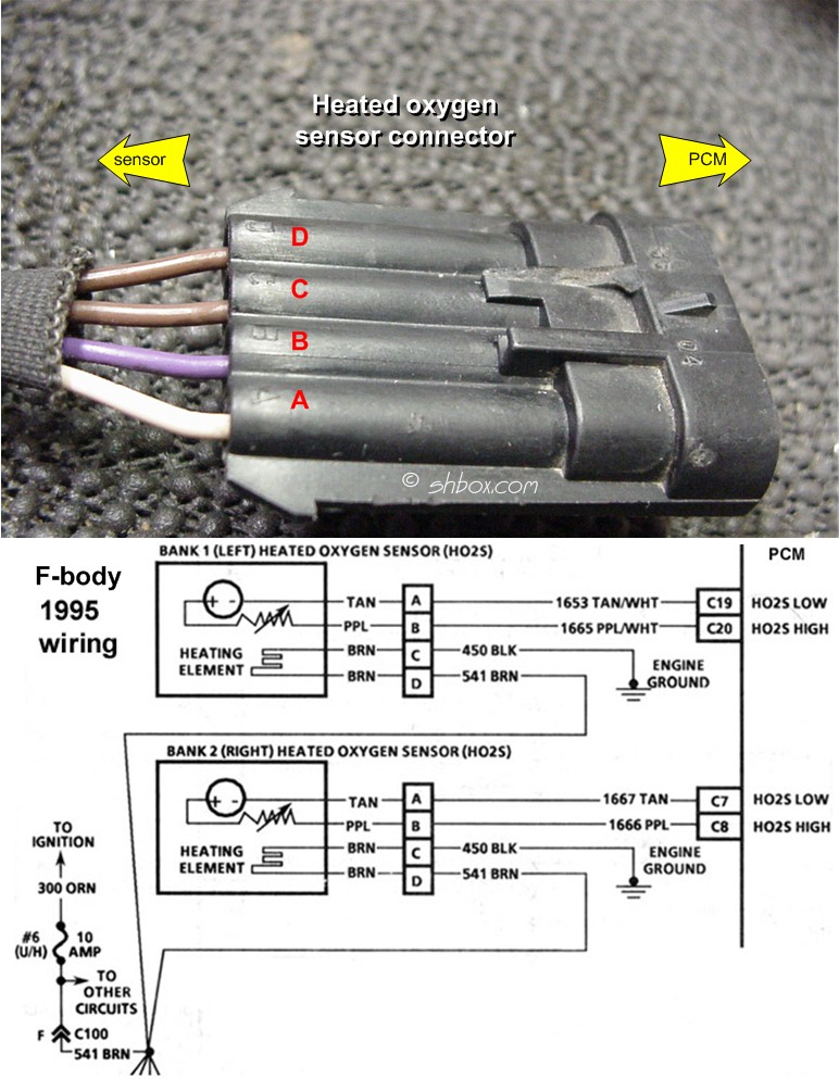
actually i dont want to give up on this yet. an 02 sensor connector has four wires. Ive tried tapping into both the "high" and the "low" signal wire. Is it possible that because i dont have a sensor plugged in, the computer is just defaulting to a value of 450? (crazy scale that datamaster uses, other narrowband fluctuates around 800). Do i need to tap the narrowband signal into both the low and high PCM inputs? Why are there even two signal wires? Ive just been playing a guessing game here.

Staging Lane
Joined: Jun 2007
Posts: 72
Likes: 0
From: Syracuse, NY
If your connecting to pin c8, I believe you said. Than that should be the driver side signal wire. So if there passenger side is unplugged and your tapping into the driver side than that should cause some problems. Correct me if I'm wrong here. Unless you tapped into the wire at the o2 sensor plug.
Just thought I'd put that out there.
Just thought I'd put that out there.
TECH Senior Member
iTrader: (3)
Joined: Oct 2006
Posts: 7,564
Likes: 4
From: Decatur, TN (N-W of Athens)
If your connecting to pin c8, I believe you said. Than that should be the driver side signal wire. So if there passenger side is unplugged and your tapping into the driver side than that should cause some problems. Correct me if I'm wrong here. Unless you tapped into the wire at the o2 sensor plug.
Just thought I'd put that out there.
Just thought I'd put that out there.
I'm curious about this whole AC Pressure thinger. I don't quite understand what's going on here heh.
If your connecting to pin c8, I believe you said. Than that should be the driver side signal wire. So if there passenger side is unplugged and your tapping into the driver side than that should cause some problems. Correct me if I'm wrong here. Unless you tapped into the wire at the o2 sensor plug.
Just thought I'd put that out there.
Just thought I'd put that out there.
Doesnt matter now, i welded up a new y-pipe (much better than my old one) and am running the 2 narrowbands as stock now.