


Flywheel Runout...?

Thread Starter
Registered User
Joined: Jan 2012
Posts: 8
Likes: 0
From: Cincinnati
Upgrading the stock clutch to a SPEC stage 2+......
Just bolted on my flywheel being careful to torque the bolts in stages (15-37-74 ft.lb.) Thought I'd just check the disc contact face for circular runout with the dial test indicator. What I found was .006" FIR (full indicator reading) when measured towards the outer rim just inboard of the pressure plate threaded holes.
Does anyone think this is excessive?
This is a stock steel flywheel that has just been resurfaced.
1999 Z28
i could be wrong but i don't think your getting a valid measurement due to other factors, i.e. crankshaft end play. I don't think you can accurately measure flywheel run out with it mounted to a crankshaft that has end play. I could be wrong, hopefully someone who is sure will chime in
Thread Starter
Registered User
Joined: Jan 2012
Posts: 8
Likes: 0
From: Cincinnati
You're right, the crankshaft end play could potentially be a factor.
I turned the flywheel about 6 times by wrenching on the bolts that fasten it to the crankshaft after they had been torqued. I was pressing hard to keep the wrench on the bolt heads while overcoming the compression in the cylinders so I'm guessing I had the crank loaded forward in the bearings.
On each turn the DTI was consistently reading a gradual increase to .006" in the same area then falling steadily back to .000" at 180 degrees on the other side.

Teching In
Joined: Aug 2005
Posts: 43
Likes: 0
If It were me, I'd get the flywheel on a surface plate and check it that way, similar to how one might tram a mill head to the table.
Mounting it to a face plate on a lathe would tell you if that runout is there or not also.
You might try indexing the wheel to the bolt holes/crank, rotate 180 deg, reinstall then recheck using your tried method to see if the runout follows the move or remains with the indexed start point.
Interesting issue though, might explain a lot of the shudder in these type systems.
Thread Starter
Registered User
Joined: Jan 2012
Posts: 8
Likes: 0
From: Cincinnati
I've checked it on a granite kitchen work top and I'm quite sure the friction disk side, which was the only side resurfaced, is extemely flat.
The problem I think, is the crank shaft mounting face of the flywheel, which was not resurfaced, is not quite parallel to the friction disk face!
Tboh: You talk like a fellow toolmaker/machinist! Anyway, I agree with you, any of your inspection methods would confirm this theory.
Also, I think I can prove how this happens during the grinding operation... I've drawn up a couple of CAD pictures which I need to post. Stay tuned...
A question: Does anyone get both faces of a flywheel resurfaced?
Trending Topics
Thread Starter
Registered User
Joined: Jan 2012
Posts: 8
Likes: 0
From: Cincinnati
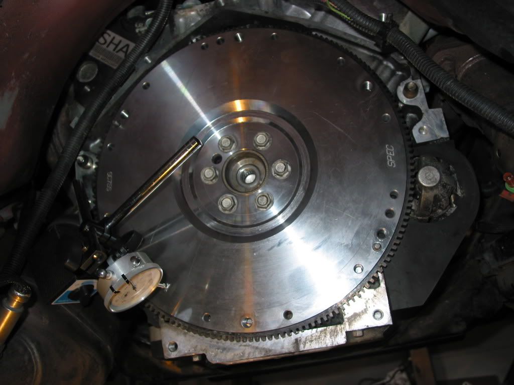
Rather than using my resurfaced cast steel flywheel I decided to buy a new one and went with the SPEC steel billet SC75S, which, I thought was extremely well manufactured Thank you SPEC!
Anyway, after torquing down the flywheel I thought I'd just check the circular run-out again on the friction face of the flywheel and to my surprise the same .006", as I saw on the resurfaced flywheel, was still there. I have to assume the error is related to the crankshaft mating face. I did clean the crankshaft mating surface well and even rubbed over it with some steel wool.
This was my inspection set-up with the magnetic DTI clamped to the catalytic converter:
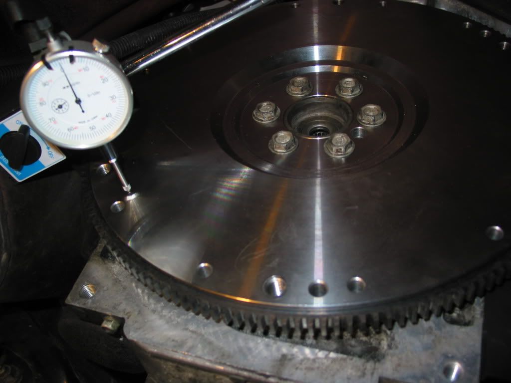
Zooming in a little and zeroing the DTI:
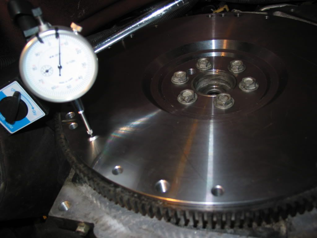
Rotated the flywheel numerous times in case the end play in the crankshaft bearings was affecting the reading but the .006" persisted at 180 degrees to the .000" reading:
I can't fix this condition so I will just have to continue on. Also, other issues with the new slave are now come to light!
Anyway, after torquing down the flywheel I thought I'd just check the circular run-out again on the friction face of the flywheel and to my surprise the same .006", as I saw on the resurfaced flywheel, was still there. I have to assume the error is related to the crankshaft mating face. I did clean the crankshaft mating surface well and even rubbed over it with some steel wool.
This was my inspection set-up with the magnetic DTI clamped to the catalytic converter:
Zooming in a little and zeroing the DTI:
Rotated the flywheel numerous times in case the end play in the crankshaft bearings was affecting the reading but the .006" persisted at 180 degrees to the .000" reading:
I can't fix this condition so I will just have to continue on. Also, other issues with the new slave are now come to light!
LS1 Tech Stories
The Best V8 Stories One Small Block at Time

Topdon ONE vs. Artidiag 800 BT2: Which is the Diagnostic Tablet For You?
Pouria Savadkouei
Gas Monkey Built a 6-Wheel Ferrari Testarossa With a Corvette LT4 Engine
Verdad Gallardo
7 Most Reliable High-Performance Engines GM Has Ever Built
Verdad Gallardo
Amazing '71 Camaro Restomod Is Modern Muscle Car Under the Skin
Verdad Gallardo
6 Common C5 Corvette Failures and What's Involved In Repairing Them
Pouria Savadkouei
Retro Modern Bandit Pontiac Trans AM Comes With Burt Reynolds' Autograph
Verdad Gallardo
Top 10 Greatest Cadillac V Series Performance Models Ever, Ranked
Pouria Savadkouei
Top 10 Most Powerful Chevy Trucks Ever Made!

Hennessey's New Supercharged Silverado ZR2 Has 700 HP
Verdad Gallardo
TECH Veteran


Joined: Apr 2008
Posts: 4,985
Likes: 112
I would suspect you need to measure runout of FW on a lathe or other "non installed" fashion as the crank end play and the inconsistant rotation of motor under compression is a factor distorting the measurements.

Lay the flywheel down, put a straight edge across it and shine a flashlight from the rear of the straight edge, what do you see?
And or
Pull the flywheel and do the same test with the dial indicator on the face of the crank.
And or
Pull the flywheel and do the same test with the dial indicator on the face of the crank.
Teching In
Joined: Aug 2005
Posts: 43
Likes: 0
I've checked it on a granite kitchen work top and I'm quite sure the friction disk side, which was the only side resurfaced, is extemely flat.
The problem I think, is the crank shaft mounting face of the flywheel, which was not resurfaced, is not quite parallel to the friction disk face!
Tboh: You talk like a fellow toolmaker/machinist! Anyway, I agree with you, any of your inspection methods would confirm this theory.
Also, I think I can prove how this happens during the grinding operation... I've drawn up a couple of CAD pictures which I need to post. Stay tuned...
A question: Does anyone get both faces of a flywheel resurfaced?
The problem I think, is the crank shaft mounting face of the flywheel, which was not resurfaced, is not quite parallel to the friction disk face!
Tboh: You talk like a fellow toolmaker/machinist! Anyway, I agree with you, any of your inspection methods would confirm this theory.
Also, I think I can prove how this happens during the grinding operation... I've drawn up a couple of CAD pictures which I need to post. Stay tuned...
A question: Does anyone get both faces of a flywheel resurfaced?
 Made me smile.
PS. Did this flywheel turn out to be flat or was it a pringle potato chip?