


Nitrous Related Wiring
11 Second Club
iTrader: (32)
Joined: Jan 2006
Posts: 3,701
Likes: 2
From: Southaven, MS (near Memphis, TN)
Originally Posted by Ray@Nitrous Outlet

the heater and opener are on independant circuits
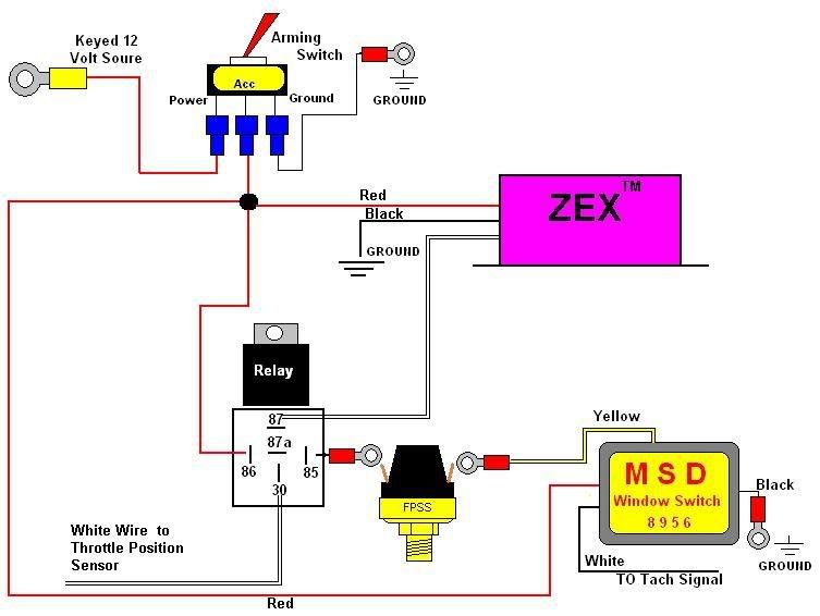
Can't the N2Outlets window switch be used as WOT activation also? Why is there one of this diagram? or can I just ignore that...
Also, that green wire on the 87 side of the relay says going to Crane ignition module.. Since I do not have that..would I not use the 87?
Last edited by jetlag; Jun 13, 2007 at 05:56 PM.

Closed ex-Sponsor Account
iTrader: (1)
Joined: Jul 2004
Posts: 2,797
Likes: 0
From: Wichita Falls, TX
Originally Posted by jetlag
Or what about the wiring diagram?

Where would the FPSS wire up in this one??
Where would the FPSS wire up in this one??
LS1 Tech Stories
The Best V8 Stories One Small Block at Time

Amazing '71 Camaro Restomod Is Modern Muscle Car Under the Skin
Verdad Gallardo
6 Common C5 Corvette Failures and What's Involved In Repairing Them
Pouria Savadkouei
Retro Modern Bandit Pontiac Trans AM Comes With Burt Reynolds' Autograph
Verdad Gallardo
Top 10 Greatest Cadillac V Series Performance Models Ever, Ranked
Pouria Savadkouei
Top 10 Most Powerful Chevy Trucks Ever Made!

Hennessey's New Supercharged Silverado ZR2 Has 700 HP
Verdad Gallardo
Coachbuilt N2A Anteros Is an LS2-Powered C6 Corvette In Italian Clothes
Verdad Gallardo
Awesome K5 Blazer Restomod Comes With C7 Corvette Power
Verdad Gallardo
10 Camaros You Should Never Buy
11 Second Club
iTrader: (32)
Joined: Jan 2006
Posts: 3,701
Likes: 2
From: Southaven, MS (near Memphis, TN)
Originally Posted by NXRICKY
cut the yellow wire,,, So if you loose fps the relay will not click.
Ok...sorry I'm not that good with wiring... cut the yellow wire, and put each end on one terminal of the fpss?

Can anybody help me? TNT F1, FJO Dual Channel Wideband (acts as TPS/WOT and window switch as well as shuts the spray down if it goes lean) Harlan 2-step, HSW stand alone fuel and 860 heated bracket.
11 Second Club
iTrader: (32)
Joined: Jan 2006
Posts: 3,701
Likes: 2
From: Southaven, MS (near Memphis, TN)
Also..should i put a fuse in this diagram anywhere...or is the relay good for that?
The purge will be easy to hook up..but should I attach a fuse to the power for it also? Or use one of those Add-a-link fuse things for the fuse box...

Well first off let me thank FJO for hooking me up with Rick at Trick Performance. He is the reason that I have this at all. Also Todd157k for the help in getting the Timing Tuner hook up figured out. I couldent have done it with out their help.
Some info about the setup:
1. This is for an FJO Progressive Nitrous Mini-Controller part# KWS0022.
2. All stage 1 is designed to do is controll both solenoids.
3. All stage 2 is designed to do is controll the ON / OFF of the Timing Tuner. It still needs to be set according to the directions that came with the unit. If you don't have them here ya go: http://www.fullthrottlenetwork.com/showthread.php?t=907
4. Settings for stage 2:
a. From trigger to cutoff it must be set to 100%
b. Trigger can be before, the same as or after the stage 1 nitrous trigger depending on what you need the timing to do.
c. Cutoff can be set to the same as or after the stage 1 nitrous cutoff depending on what you need the timing to do. I was advised not to set the timing cutoff for before the nitrous stops spraying.
5. All wires are 18ga. unless stated. For theses wires you should not go smaller due to current draw. You could go bigger ie. 16ga. 14ga. etc.
6. For the listed 12ga. wires. This is the min size that they should be. Again you can go bigger if you want.
With all that said. Here ya'll go. I hope that this helps someone.

How should my nitrous be wired with a timing tuner? activation switch, timing tuner, wot, then soleniods Or activation switch, wot, timing tuner, then soleniods. I had it the 2nd way last year and it kept backfiring and then I blew an intake off of it, then pulled timing through a laptop and it was fine. I don't know if it wasn't pulling timing fast enough with it wired between the wot switch and the soleniods
Thanks for any help
Thanks for any help
Teching In
Joined: Dec 2006
Posts: 26
Likes: 0
From: Ada, OK
How do i wire up my harlen 2 step to my Nitrous outlet WOT switch where it wont spray while its activated. I have seen several people ask this same question with no luck. I have seen something about a relay or something ?
Last edited by NOSjunky; Jun 28, 2007 at 08:28 AM.
After numerous questions on how to wire the IAT, timing pull trick.
Here is some additional info for the schematic posted earlier.
For years 1999 and 2000, and C5s these are the wires your looking at:
On the PCM Red Connector,
#25 Tan wire
IAT Sensor
#57 Purple wire
IAT ground
So for this diagram,

Tan wire would go to "A",
and purple wire would go to "B".
Now I am not sure if these wires changed in latter years, or prior years (but think at least prior years are the same), but a PCM pinout can be had for any year, if ya do your home work. I haven't used this or messed with it for a few years, so...
Anyway, I hope this clarifies some of the wiring for this trick. Oh and a 750 ohm resistor will pull about 3 to 4 degrees of timing.
Robert
Here is some additional info for the schematic posted earlier.
For years 1999 and 2000, and C5s these are the wires your looking at:
On the PCM Red Connector,
#25 Tan wire
IAT Sensor
#57 Purple wire
IAT ground
So for this diagram,
Tan wire would go to "A",
and purple wire would go to "B".
Now I am not sure if these wires changed in latter years, or prior years (but think at least prior years are the same), but a PCM pinout can be had for any year, if ya do your home work. I haven't used this or messed with it for a few years, so...
Anyway, I hope this clarifies some of the wiring for this trick. Oh and a 750 ohm resistor will pull about 3 to 4 degrees of timing.
Robert
Last edited by Robert56; Jul 9, 2007 at 09:03 PM.
Originally Posted by Robert56
After numerous questions on how to wire the IAT, timing pull trick.
Here is some additional info for the schematic posted earlier.
For years 1999 and 2000, and C5s these are the wires your looking at:
On the PCM Red Connector,
#25 Tan wire
IAT Sensor
#57 Purple wire
IAT ground
So for this diagram,
Tan wire would go to "A",
and purple wire would go to "B".
Now I am not sure if these wires changed in latter years, or prior years (but think at least prior years are the same), but a PCM pinout can be had for any year, if ya do your home work. I haven't used this or messed with it for a few years, so...
Anyway, I hope this clarifies some of the wiring for this trick. Oh and a 750 ohm resistor will pull about 3/4 degrees of timing.
Robert
Jerry