
Dry Shot wiring diagram HELP!
 07-30-2008, 06:12 PM
#1
On The Tree
Thread Starter
iTrader: (6)
Join Date: May 2008
Location: Vero Beach
Posts: 103
Likes: 0
Received 0 Likes
on
0 Posts
Here is a diagram i made for my simple dry shot im going to run. Can someone double check my work and make sure my wiring is right? i may change where the wot switch is and put it between the arm switch and the 86 pin on the relay. i dont think there is any difference but thats why im asking lol. anyone have a recommendation for the fuse? i was going to use a 10 amp, that should be enough.
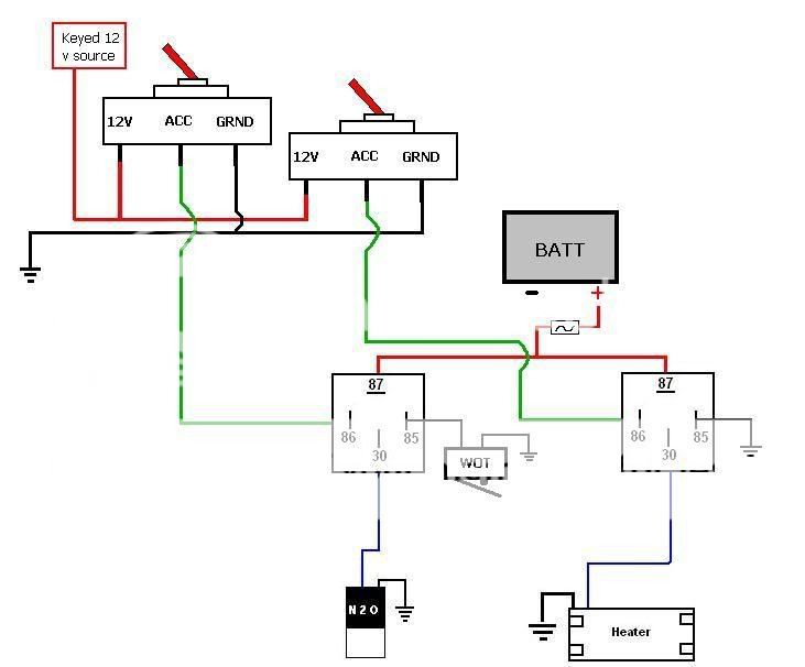
im not going to purge the system. i have maybe $100 in the whole setup, most of the cost came from the new dynotune solenoid. i have two bottles for the neon so one got donated to the firebird.
im not going to purge the system. i have maybe $100 in the whole setup, most of the cost came from the new dynotune solenoid. i have two bottles for the neon so one got donated to the firebird.
 07-30-2008, 09:11 PM
#3
TECH Addict
iTrader: (24)

Join Date: Jun 2003
Location: St Joe, MO
Posts: 2,645
Likes: 0
Received 0 Likes
on
0 Posts

30 is the common and if the relay has an 87a terminal could be an issue if he's not careful. I would strongly suggest getting a window switch for the nitrous control. Otherwise looks fine to me, except you forgot the heater pressure switch if there is one.
07-31-2008, 07:28 PM
#6
On The Tree
Thread Starter
iTrader: (6)
Join Date: May 2008
Location: Vero Beach
Posts: 103
Likes: 0
Received 0 Likes
on
0 Posts
but dyno tune has power to 30 and 87 to the heater,
http://www.dynotunenitrous.com/store...R%20WARMER.pdf
my relays are radio shack special, the wiring diagram on the back of the package has pin 87 as 12V in, and 30 to the accessory.
im a little confused as to why, different companies use different pins? maybe its just different relay companies designs?
im not going to use a bottle heater pressure switch. i have a bottle gauge and im just going to monitor the bottle pressure. im not running a big shot yet. i have plans for the car later with a two stage set up. but for now i just want a small shot to get me in the mid 12s.
07-31-2008, 09:37 PM
#7
it really doesn't matter which wire (30 & 87) you run it to. The point was made that it's just.. physically, 87a (if you had one) is close and could touch a hot wire. Since you don't have it, don't worry about it.
Since it's obvious you're building this on a budget, spend $25 and get a FPSS. It may save your motor.
Since it's obvious you're building this on a budget, spend $25 and get a FPSS. It may save your motor.
Trending Topics
 08-07-2008, 10:48 PM
#9
12 Second Club
iTrader: (3)
Join Date: Apr 2006
Location: Columbia, SC
Posts: 434
Likes: 0
Received 0 Likes
on
0 Posts
it really doesn't matter which wire (30 & 87) you run it to. The point was made that it's just.. physically, 87a (if you had one) is close and could touch a hot wire. Since you don't have it, don't worry about it.
Since it's obvious you're building this on a budget, spend $25 and get a FPSS. It may save your motor.
Since it's obvious you're building this on a budget, spend $25 and get a FPSS. It may save your motor.
08-08-2008, 11:01 AM
#10
On The Tree
Thread Starter
iTrader: (6)
Join Date: May 2008
Location: Vero Beach
Posts: 103
Likes: 0
Received 0 Likes
on
0 Posts
OK guys need some more help!!! after starting the project im thinking of changing the wiring around some. the biggest thing would be moving the wot switch from the 85 pin on the relay to the ground side of the solenoid? i have the "zippy" brand wot switch from an old NX kit. on the side of the switch it says its rated to 10amps. is there any difference or reason i should not run the switch there? the reason for the move is because the relays are going to be inside the car and the wot is getting mounted to the throttle body. so if i run the switch to the relay i have to run another wire all through the engine bay.
heres the diagram.
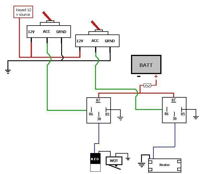
heres the diagram.
08-08-2008, 12:44 PM
#11
TECH Addict
iTrader: (24)
Join Date: Jun 2003
Location: St Joe, MO
Posts: 2,645
Likes: 0
Received 0 Likes
on
0 Posts
OK guys need some more help!!! after starting the project im thinking of changing the wiring around some. the biggest thing would be moving the wot switch from the 85 pin on the relay to the ground side of the solenoid? i have the "zippy" brand wot switch from an old NX kit. on the side of the switch it says its rated to 10amps. is there any difference or reason i should not run the switch there? the reason for the move is because the relays are going to be inside the car and the wot is getting mounted to the throttle body. so if i run the switch to the relay i have to run another wire all through the engine bay.
heres the diagram.
heres the diagram.