


 Let me look a little closer...
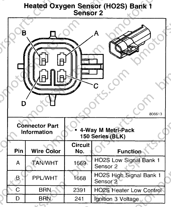
Wiring Diagram
Connector Part Information
12176897
4-Way F Metri-Pack 150 Series (GRY)
Pin
Wire Color
Circuit No.
Function
A
TAN/WHT
1653
HO2S Low Signal Bank 1 Sensor 1
B
PPL/WHT
1665
HO2S High Signal Bank 1 Sensor 1
C
BLK/WHT
3113
HO2S Heater Low Control
D
BRN
241
Ignition 3 Voltage
12176897
4-Way F Metri-Pack 150 Series (GRY)
Pin
Wire Color
Circuit No.
Function
A
TAN/WHT
1653
HO2S Low Signal Bank 1 Sensor 1
B
PPL/WHT
1665
HO2S High Signal Bank 1 Sensor 1
C
BLK/WHT
3113
HO2S Heater Low Control
D
BRN
241
Ignition 3 Voltage

Former Vendor
Joined: Mar 2009
Posts: 39
Likes: 0
Second, here is the male / plug side in our standard connector or connector kit (terminals + seals + tpas/cpas added) or pigtail:
http://www.bmotorsports.com/shop/adv...bcat=1&x=0&y=0
Here is the female / receptacle side in our standard connector or connector kit (terminals + seals + tpas/cpas added) or pigtail:
http://www.bmotorsports.com/shop/adv...bcat=1&x=0&y=0
Third, please do not use those unsealed plastic butt connectors in your image on any connection exposed to the environment! EVER! Said unsealed connectors make any person familiar with automotive/industrial/aerospace wiring cringe. This is a very common failure mode for automotive electrical connections and should be avoided at all costs! There are two great options that are sealed and meant for exposure to the underside of a vehicle:
A: Heatshrink & adhesive lined butt connectors -> http://www.bmotorsports.com/shop/pro...roducts_id/421
B: Non-insulated butt connectors + adhesive lined heatshrink -> http://www.bmotorsports.com/shop/pro...roducts_id/932+ http://www.bmotorsports.com/shop/ind...th/117_161_163
I noticed that Alldata has the black variation of this connector mating with the light gray version of this connector (they have different keyways) in some locations. Either way, we stock both the black and light gray version on our website. Last edited by Bmotorsports; Mar 28, 2009 at 05:55 PM. Reason: Difference between black 4 way connector in original post.
I got all the parts in and everything wired up. The LM1 is simulating my front O2 sensor but I am not sure I have the settings set correctly for the analog output 1. The settings now are: 0.924 Volt at 14.29 AFR and 0 volt at 14.98 AFR. Respond speed: instant
I am also throwing a p0155 code. I noticed in the guide I was following the O2 sensor wiring is different. Slot C on the guide is a ground and slot C on mine is HO2S heater low control. Any idea on what I need to do with this wire so it will stop throwing the code?
Guide O2:

My O2:
I am also throwing a p0155 code. I noticed in the guide I was following the O2 sensor wiring is different. Slot C on the guide is a ground and slot C on mine is HO2S heater low control. Any idea on what I need to do with this wire so it will stop throwing the code?
Guide O2:
My O2:
Attached is the diagram you need. Just use the wire colors instead of pin designations.
You need the voltages on that wideband moved more. You are way too close to stoich on both of your parameters. Your max lean should be 0V, and your max rich should be 1, whatever that case may be. Your wideband will of course, read a lot further out in both directions, so you'll have to move your voltages around according to what it says.
You need the voltages on that wideband moved more. You are way too close to stoich on both of your parameters. Your max lean should be 0V, and your max rich should be 1, whatever that case may be. Your wideband will of course, read a lot further out in both directions, so you'll have to move your voltages around according to what it says.
Trending Topics
LS1 Tech Stories
The Best V8 Stories One Small Block at Time

Topdon ONE vs. Artidiag 800 BT2: Which is the Diagnostic Tablet For You?
Pouria Savadkouei
Gas Monkey Built a 6-Wheel Ferrari Testarossa With a Corvette LT4 Engine
Verdad Gallardo
7 Most Reliable High-Performance Engines GM Has Ever Built
Verdad Gallardo
Amazing '71 Camaro Restomod Is Modern Muscle Car Under the Skin
Verdad Gallardo
6 Common C5 Corvette Failures and What's Involved In Repairing Them
Pouria Savadkouei
Retro Modern Bandit Pontiac Trans AM Comes With Burt Reynolds' Autograph
Verdad Gallardo
Top 10 Greatest Cadillac V Series Performance Models Ever, Ranked
Pouria Savadkouei
Top 10 Most Powerful Chevy Trucks Ever Made!

Hennessey's New Supercharged Silverado ZR2 Has 700 HP
Verdad Gallardo So you need to know what the analog should be at a given afr? As far as what your stock sensor would show?
Back to the P0155:Low control and ground are the same thing, just worded differently. I don't know if there is an issue with the wiring between the H02S and the PCM or what, but for it to control the heater, it grounds that circuit. If you command the heaters on, you should see full unimpeded ground on that circuit and of course 12v on terminal D through fuse 15 on the PCM side of the connector. If you have those two items, you either have a bad heater (sensor) or a bad PCM. What does your splice do after that? I know the LM1 controls its own heater, so you probably aren't wired in to anything? You could put a resistor looped in between those two circuits if that is the case.
Back to the P0155:Low control and ground are the same thing, just worded differently. I don't know if there is an issue with the wiring between the H02S and the PCM or what, but for it to control the heater, it grounds that circuit. If you command the heaters on, you should see full unimpeded ground on that circuit and of course 12v on terminal D through fuse 15 on the PCM side of the connector. If you have those two items, you either have a bad heater (sensor) or a bad PCM. What does your splice do after that? I know the LM1 controls its own heater, so you probably aren't wired in to anything? You could put a resistor looped in between those two circuits if that is the case.
Last edited by deadhorse66; Apr 6, 2009 at 02:43 AM.
So you need to know what the analog should be at a given afr? As far as what your stock sensor would show?
Back to the P0155:Low control and ground are the same thing, just worded differently. I don't know if there is an issue with the wiring between the H02S and the PCM or what, but for it to control the heater, it grounds that circuit. If you command the heaters on, you should see full unimpeded ground on that circuit and of course 12v on terminal D through fuse 15 on the PCM side of the connector. If you have those two items, you either have a bad heater (sensor) or a bad PCM. What does your splice do after that? I know the LM1 controls its own heater, so you probably aren't wired in to anything? You could put a resistor looped in between those two circuits if that is the case.
Back to the P0155:Low control and ground are the same thing, just worded differently. I don't know if there is an issue with the wiring between the H02S and the PCM or what, but for it to control the heater, it grounds that circuit. If you command the heaters on, you should see full unimpeded ground on that circuit and of course 12v on terminal D through fuse 15 on the PCM side of the connector. If you have those two items, you either have a bad heater (sensor) or a bad PCM. What does your splice do after that? I know the LM1 controls its own heater, so you probably aren't wired in to anything? You could put a resistor looped in between those two circuits if that is the case.
BTW: Here is the guide I was following so you get the idea of what I am trying to do. http://www.thetuningdoctor.com/wb02new.htm
Here is the settings used on the LM1 from the guide:

OK, went out and grabbed meter to check out my voltages.
When I connect A - Low Signal and D + ignition I get 12 volts.
When I connect C - Low Control and D + ignition I get somewhere around 9 volts.
What am I missing here?
When I connect A - Low Signal and D + ignition I get 12 volts.
When I connect C - Low Control and D + ignition I get somewhere around 9 volts.
What am I missing here?
A code P0155 may mean that one or more of the following has happened:
O2 Heater element resistance is high
Internal short or open in the heater element
O2 heater circuit wiring high resistance
open or short to ground in the wiring harness
I need some kind of resistor in between connections C and D. I kind of dived in a little over my head
 . Would you know what I would need to make this work? Thanks for your help!
 Former Vendor
Joined: Mar 2009
Posts: 39
Likes: 0
Ok, after beating my head on the desk a couple of times I get it.
A code P0155 may mean that one or more of the following has happened:
O2 Heater element resistance is high
Internal short or open in the heater element
O2 heater circuit wiring high resistance
open or short to ground in the wiring harness
I need some kind of resistor in between connections C and D. I kind of dived in a little over my head. Would you know what I would need to make this work? Thanks for your help!
A code P0155 may mean that one or more of the following has happened:
O2 Heater element resistance is high
Internal short or open in the heater element
O2 heater circuit wiring high resistance
open or short to ground in the wiring harness
I need some kind of resistor in between connections C and D. I kind of dived in a little over my head
. Would you know what I would need to make this work? Thanks for your help!You install in a high power resistor that is equivalent to the stock o2 sensor heater circuit resistance. It should not be under the car and exposed to the environment as they are not typically fully sealed and should be placed in a well ventilated area where the heat they generate cannot cause a fire. If needed you can put multiple resistors in series to match your needs. Alldata didn't enlighten me on the value of the heater circuit resistance unfortunately.
Ok, I got everything wired up and working correctly. Now the only thing left is what settings should I use in my analog output 1 on my LM1 to simulate the O2.
The settings I have plugged in now are: 0.924 Volt at 14.29 AFR and 0 volt at 14.98 AFR. Respond speed: 1/12 sec
Example:
The settings I have plugged in now are: 0.924 Volt at 14.29 AFR and 0 volt at 14.98 AFR. Respond speed: 1/12 sec
Example:
Sorry I haven't been back with you on this, it slipped my mind. The resistance value you need for the heater element is taken from across pins c and d on the sensor. Measure it and put a resistor of equal value in loop there per what Mr. Ballenger says. He nailed it. Deleting P0155 shouldn't have a negative effect on anything, as your LM1 takes care of all that on its own. I hope this helps. I'll try to keep a better eye on this thread, or just PM me if you need any more help.
I'm still a little confused on what you are trying to do with the rich/lean voltage values. Are you trying to fool the PCM? If not, you want your voltage to make a nice smooth slope from 1V @ 7.4:1 AFR to .05V @ 22:1. That would be close to the reading the stock sensor would give. 450mV is stoich.
I'm still a little confused on what you are trying to do with the rich/lean voltage values. Are you trying to fool the PCM? If not, you want your voltage to make a nice smooth slope from 1V @ 7.4:1 AFR to .05V @ 22:1. That would be close to the reading the stock sensor would give. 450mV is stoich.